Page 834 of 1865
7A INSPECTION
86U07A-058
63U07A-074
63U07A-075
Reverse Idle Gear
1. Worn or damaged bushing.
2. Worn or damaged teeth.
3. Worn or damaged release lever coupling groove.
4. Clearance between sleeve and reverse lever.
Standard: 0.095—0.318 mm (0.004—0.013 in)
Maximum: 0.5 mm (0.020 in)
Clutch Housing, Transaxle Case, Rear Cover,
and Differential Gear Case
Cracks or damage.
Caution
If the clutch housing, transaxle case, or
differential gear case is replaced, adjust the
bearing preload of the shaft gears and the
preload of the differential side bearings.
Bearing
1. Roughness or noise while turning
2. Worn or damaged outer race or rollers
Caution
a) Replace the bearing, the outer race, and the
inner race as a unit.
b)lf the bearing is replaced, adjust the
preload.
Speedometer Driven Gear Assembly
1. Worn or damaged teeth.
2. Worn or damaged O-ring.
Ring Gear Speedometer Drive Gear
Worn or damaged teeth.
Oil Seal
Damaged or worn lip.
63U07A-076
7A—28
Page 843 of 1865
ASSEMBLY 7 A
Bearing Preload
Adjust the bearing preload through the use of adjust shim(s).
83U07A-099
49 G030 381
Outer race
Differential
Outer races
Secondary shaft
assembly
49 G030 382A
Transaxle case
Outer rases
Primary shaft assembly
Outer rase
49 F401 382A
Clutch housing
83U07A-033
7A-37
Page 844 of 1865

7 A ASSEMBLY
Outer race
Selector
76G07A-032
i "k
49 G030 381
49 G030 382A
49 G030 382A
76G07A-033
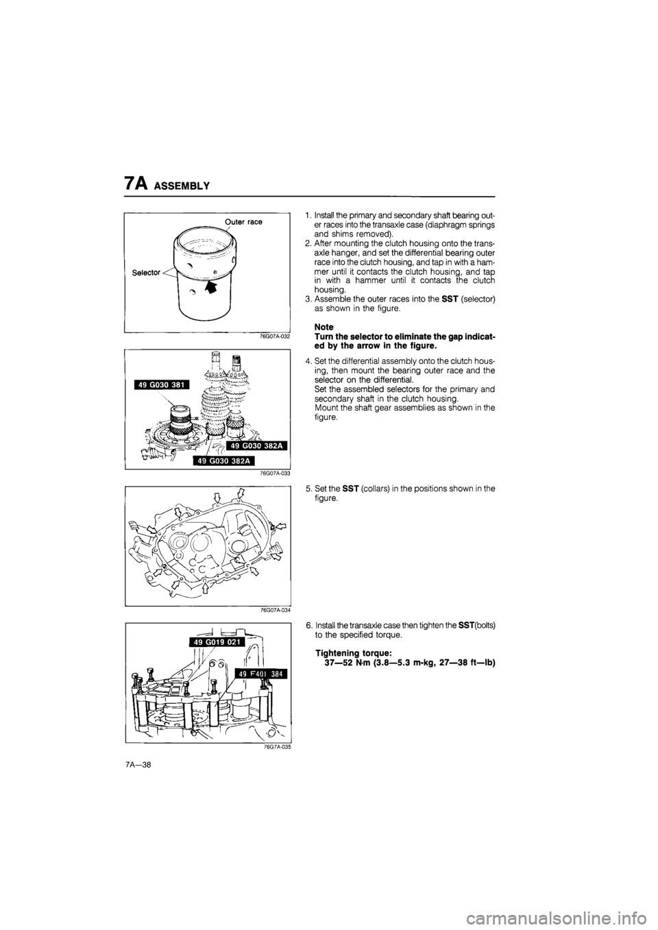
1. Install the primary and secondary shaft bearing out-
er races into the transaxle case (diaphragm springs
and shims removed).
2. After mounting the clutch housing onto the trans-
axle hanger, and set the differential bearing outer
race into the clutch housing, and tap in with a ham-
mer until it contacts the clutch housing, and tap
in with a hammer until it contacts the clutch
housing.
3. Assemble the outer races into the SST (selector)
as shown in the figure.
Note
Turn the selector to eliminate the gap indicat-
ed by the arrow in the figure.
4. Set the differential assembly onto the clutch hous-
ing, then mount the bearing outer race and the
selector on the differential.
Set the assembled selectors for the primary and
secondary shaft in the clutch housing.
Mount the shaft gear assemblies as shown in the
figure.
5. Set the SST (collars) in the positions shown in the
figure.
76G07A-034
6. Install the transaxle case then tighten the SST(bolts)
to the specified torque.
Tightening torque:
37—52
N
m (3.8—5.3 m-kg, 27—38 ft—lb)
76G7A-035
7A-38
Page 846 of 1865

7A ASSEMBLY
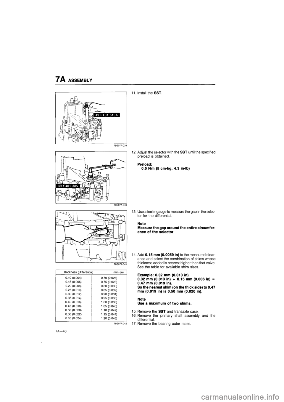
11. Install the SST.
76G07A-039
76G07A-040
76G07A-041
Thickness (Differential)
mm
(in)
0.10 (0.004) 0.70 (0.026)
0.15 (0.006) 0.75 (0.028)
0.20 (0.008) 0.80 (0.030)
0.25 (0.010) 0.85 (0.032)
0.30 (0.012) 0.90 (0.034)
0.35 (0.014) 0.95 (0.036)
0.40 (0.016) 1.00 (0.038)
0.45 (0.018) 1.05 (0.040)
0.50 (0.020) 1.10 (0.042)
0.60 (0.022) 1.15 (0.044)
0.65 (0.024) 1.20 (0.046)
12. Adjust the selector with the SST until the specified
preload is obtained.
Preload:
0.5 N-m (5 cm-kg, 4.3 in-lb)
13. Use a feeler gauge to measure the gap in the selec-
tor for the differential.
Note
Measure the gap around the entire circumfer-
ence of the selector
76G07A-042
14. Add 0.15 mm (0.0059 in) to the measured clear-
ance and select the combination of shims whose
thickness added is nearest higher than that valve.
See the table for available shim sizes.
Example: 0.32 mm (0.013 in)
0.32 mm (0.013 in) + 0.15 mm (0.006 in) =
0.47 mm (0.019 in).
So the nearest shim (on the thick side) to 0.47
mm (0.019 in) is 0.50 mm (0.020 in).
Note
Use a maximum of two shims.
15. Remove the SST and transaxle case.
16. Remove the primary shaft assembly and the
differential.
17. Remove the bearing outer races.
7A—40
Page 849 of 1865

ASSEMBLY 7A
76G07A-044
76G07A-045
Bearing Preload
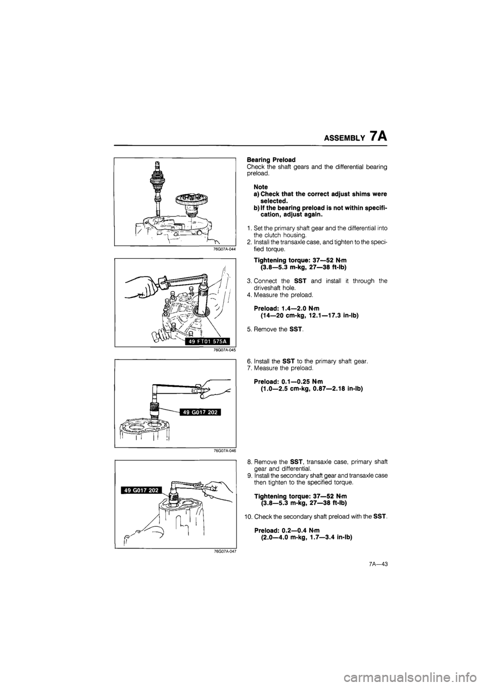
Check the shaft gears and the differential bearing
preload.
Note
a) Check that the correct adjust shims were
selected.
b) If the bearing preload is not within specifi-
cation, adjust again.
1. Set the primary shaft gear and the differential into
the clutch housing.
2. Install the transaxle case, and tighten to the speci-
fied torque.
Tightening torque: 37—52 N-m
(3.8—5.3 m-kg, 27—38 ft-lb)
3. Connect the SST and install it through the
driveshaft hole.
4. Measure the preload.
Preload: 1.4—2.0 N-m
(14—20 cm-kg, 12.1—17.3 in-lb)
5. Remove the SST.
6. Install the SST to the primary shaft gear.
7. Measure the preload.
Preload: 0.1—0.25 N-m
(1.0—2.5 cm-kg, 0.87—2.18 in-lb)
76G07A-046
8. Remove the SST, transaxle case, primary shaft
gear and differential.
9. Install the secondary shaft gear and transaxle case
then tighten to the specified torque.
Tightening torque: 37—52 N-m
(3.8—5.3 m-kg, 27—38 ft-lb)
10. Check the secondary shaft preload with the SST.
Preload: 0.2—0.4 N-m
(2.0—4.0 m-kg, 1.7—3.4 in-lb)
76G07A-047
7A-43
Page 852 of 1865

7A ASSEMBLY
8. Fit the crank lever in between the change arm and
the control end, and connect the crank lever shaft
to the crank lever.
9. Align the pin holes of the crank lever shaft and the
clutch housing, and insert the pin.
Note
Use a new O-ring for the crank lever shaft.
86U07A-113
10. Install the gate © and the shift rod ©, and tight-
en the gate mounting bolt.
Note
The mark (indicated by the arrow in the fig-
ure) and the gate mounting bolt hole must be
in the same direction.
76U07A-121
11. Install the reverse idle gear and the reverse idle
shaft.
12. Connect the magnet to the clutch housing.
13. Align the end of the interlock sleeve with the con-
trol lever indicated by the arrow, and, at the same
time, face the reverse idle shaft screw hole in the
direction shown in the figure.
76U07A-122
14. Apply a thin coat of sealant to the contact surfaces
of the clutch housing and transmission case, tight-
en the transaxle case installation bolts to the speci-
fied torque.
Tightening torque:
18—26 N m (1.8—2.7 m-kg, 13—18.8 ft-lb)
15. Insert the SST to driveshaft coupling hole.
7A-46
Page 859 of 1865
INSTALLATION 7A
1. Attach rope at 2 places on the transaxle and place
a board on the jack and position the transaxle on it.
Caution
The transaxle is not well balanced; be care-
ful when positioning on the jack.
2. Move the transaxle into the place and attach the
rope (attached to the transaxle in step 1) to the
SST
86U07A-210
3. Install the transaxle onto the engine.
Note
Lift the transaxle using the jack pulling the
rope.
Tightening torque: 89—117 N-m
(9.1—11.9 m-kg, 66—85 ft-lb)
86U07A-211
4. Install the clutch pipe.
Tightening torque:
(A), (§): 19—26 N-m
(1.9—2.6 m-kg, 14—19 ft-lb)
©: 8—11 N-m
(80—110 cm-kg, 69—95 in-lb)
76G07A-054
5. Install the engine mount bracket.
Tightening torque:
55—80 N-m (5.6—8.2 m-kg, 41—59 ft-lb)
76G07A-055
7A—53
Page 861 of 1865
INSTALLATION 7A
14. Install the clutch release cylinder.
Tightening torque: 19—26 N-m
(1.9—2.6 m-kg, 14—19 ft-lb)
76G07A-060
15. Install the gusset plates.
Tightening torque: 37—52 N-m
(3.8—5.3 m-kg, 27—38 ft-lb)
76G07A-061
16. Replace the clips at the end of the driveshafts and
joint shaft with new ones.
17. Install the joint shaft and right driveshaft as follows:
(1) Install and tighten the reamer bolts (A); then in-
stall and tighten the standard bolts (§).
Tightening torque:
® :7—10 N-m
(70—100 cm-kg, 43—61 in-lb)
(B) :42—62 Nm
(4.3—6.3 m-kg, 31—46 ft-lb)
76G07A-062
(2) Remove the SST and insert the shaft into the
transaxle.
(3) Pull the front hub outward and connect the
driveshaft to the joint shaft.
(4) Push the joint at the differential side to secure-
ly connect the driveshaft to the joint shaft.
Note
a) After installation, pull the front hub outward
to confirm that the driveshaft doesn't come
out.
b)Do not damage the oil seal.
86U07A-219
7A-55