Page 1765 of 1865

15 AUDIO SYSTEM
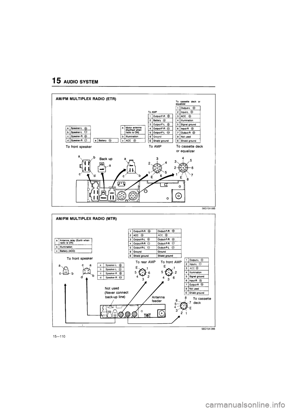
AM/FM MULTIPLEX RADIO (ETR)
To front speaker
To cassette deck or equalizer
a Speaker-L © a Motor antenna (Earthed when radio is ON) b Speaker-L ©
a Motor antenna (Earthed when radio is ON)
c Speaker-R © b Illumination
d Speaker-R © a Battery © c ACC ©
1 Output-L ©
To AMP 2 Input-L ©
1 Output-F-R © 3 ACC ©
2 Battery © 4 Illumination
3 Output-F-L © 5 Signal ground
4 Output-F-R © 6 Input-R ©
5 Output-F-L © 7 Output-R ©
6 Ground 8 Not used
E Shield ground E Shield ground
To AMP To cassette deck
or equalizer
56G15X085
AM/FM MULTIPLEX RADIO (MTR)
a Antenna relay (Earth when radio is ON)
b Illumination
c Battery (ACC)
To front speaker
c a
1 Output-R-R © Output-F-R ©
2 ACC © ACC ©
3 Output-R-L © Output-F-R ©
4 Output-R-R © Output-F-R ©
5 Output-R-L © Output-F-L ©
6 Ground Ground
E Shield ground Shield ground
a Speaker-L ©
b Speaker-L ©
c Speaker-R ©
d Speaker-R ©
To rear AMP To front AMP
Not used
(Never connect
back-up line)
1 Output-L ©
2 Input-L ©
3 ACC ©
4 Illumination
5 Signal ground
6 Input-R ©
7 Output-R ©
8 Not used
E Shield ground
To cassette
deck
56G15X-086
15-110
Page 1766 of 1865
AUDIO SYSTEM 1 5
CASSETTE DECK
To radio
a Antenna relay (Earthed when radio is ON)
b Illumination
c Battery (ACC) ©
Battery (ACC)©
. • Q-
fi0
m
®
jqj
To radio
/
1 Input-L ©
2 Output-L ©
3 Battery (ACC) ©
4 Not used
5 Signal ground
6 Output-R ©
7 Input-R ©
8 Not used
E Shield ground
»
B /1 ^C
a Antenna relay (Earthed when radio is ON)
b Illumination
c Battery (ACC) ©
0
56G15X-088
CASSETTE DECK (SYSTEM 3 AND 4)
To radio
a Power antenna
b Illumination
c Battery (ACC) jm
a Not used
b Not used
c Speaker ©
d Speaker ©
To radio
JHL
a Speaker-L ©
b Speaker-L ©
c Speaker-R ©
d Speaker-R ©
To rear
Blue color
V m.
"T*.
a Power antenna
b Illumination
c Battery (ACC) ©
56G15X-089
15—111
Page 1767 of 1865
1 5 AUDIO SYSTEM
GRAPHIC EQUALIZER
1 INPUT-L ©
2 OUTPUT-L ©
3 BATTERY (ACC) ©
4 ILLUMINATION
5 SIGNAL GROUND
6 OUTPUT-R ©
7 INPUT-R ©
6 NOT USED
E SHELD GROUND
1 NOT USED
2 INPUT-L ©
3 BATTERY (ACC) ©
4 NOT USED
5 SIGNAL GROUND
6 INPUT-R ©
7 NOT USED
8 NOT USED
E SHIELD GROUND
To radio
6) (8)
To cassette deck
r
56G15X-091
AM/FM/SW RADIO WITH CASSETTE TAPE PLAYER
3 AfTtp coot
<13 2 VI
76G15X-023
15—112
Page 1768 of 1865
AUDIO SYSTEM 15
AM/FM/LW RADIO WITH CASSETTE TAPE PLAYER
S Shield ground
76G15X-024
15—113
Page 1769 of 1865
1 5 AUDIO SYSTEM
ADJUSTMENT (MTR)
Antenna adjustment
Use the following adjustment procedure to obtain op-
timum antenna and radio reception sensitivity.
1. Extend the antenna fully.
2. Set the ignition key to ACC.
3. Turn on the radio, and set it to AM reception.
4. Tune in a distant station with a weak signal at
around 1400 kHz. If such a station cannot be
found, use static to make the adjustment.
5. Turn the antenna trimmer adjustment screw to the
left and right to find the maximum sensitivity (of ei-
ther the broadcast or the static).
Note
If there is no change in the sensitivity, either
the tuned signal is too strong, or there is an
antenna malfunction or broken wire.
POWER ANTENNA
STRUCTURAL VIEW
1. Antenna motor
2. Antenna
FM M >08 ST ' I' tl -3-lx
0
[ AM s» TO too"I30"IM
J
A
FM | FM
B
I FH | fH
M FM
III
56G15X-106
15-114
Page 1770 of 1865
AUDIO SYSTEM 1 5
Power Antenna Circuit
86U15X-194
inspection Of Power Antenna Relay
1. Check the voltage at each terminal of the relay con-
nector harness side with each condition.
Terminal Condition Voltage
LW Ignition switch ACC 12V
BY Ignition switch
ON
12V
LgW Ignition switch ACC and radio
power switch
ON
OV
LR Any time 12V
76G15X-096
86U15X-196
If not, repair the harness.
2. Turn the ignition switch on, and check the opera-
tion of the power antenna with each condition.
Condition Antenna operation
GW wire
is
connected
to a
body ground Rises
GW wire
is
not connected to
a
body ground Goes down
If the power antenna does not operate, replace the
power antenna relay or power antenna motor.
15—115