Page 41 of 1865
TUNE-UP PROCEDURE 1A
High-Tension Lead
Check the following points. Clean or replace if
necessary.
1. Damaged lead
2. Carbon deposits
86U01X-014
76G01A-012
49 0187 280
76G01A-013
Carburetor Float Level (Carburetor)
1. Run the engine at idle.
2. Check that the fuel level is at the center of the float
level indicator window.
If necessary, adjust the fuel float level. (Refer to Sec-
tion 4A.)
Hydraulic Lash Adjuster (12 valve)
Note
Tappet noise may occur if the engine is not
operated for an extended period of time. The
noise should stop after the engine has
reached normal operating temperature.
1. Check for tappet noise. If noise exsits, check the
following points.
(1) Engine oil condition and level
(2) Engine oil pressure (Refer to Section 2A)
2. If the noise does not stop, check for movement of
each HLA by pushing down each rocker arm by
hand while at TDC of compression stroke.
3. If the rocker arm moves down, replace the HLA.
(Refer to page 1A—75.)
76G01A-014
1
A—9
Page 42 of 1865

1A TUNE-UP PROCEDURE
No.1 IN No.2 IN
No.1 EX No.3 EX
76G01A-015
Adjust bolt
^N^^^^^Lock nut
SsKs&b ' Valve
Camshaft >Nw clearance
76G01A-016
76G01A-017
Valve Clearance (8-valve)
1. Warm up the engine to the normal operating tem-
perature.
2. With the piston of the No.1 cylinder at TDC of com-
pression stroke.
Adjust the valve clearance as shown in the figure.
Valve clearance (valve side)
IN : 0.30 mm (0.012 in)
EX: 0.30 mm (0.012 in)
3. Turn the crankshaft one full turn so that the piston
of the No.4 cylinder is at TDC of compression
stroke.
Adjust the clearances of the remaining valves.
Ignition Timing
1. Warm up the engine and run it at idle.
2. Turn all electric loads OFF.
3. Connect a timing light tester.
4. Disconnect the vacuum hose from the vacuum
control, and plug the hose.
5. Check that the ignition timing mark (yellow) on the
crankshaft pulley and the timing mark on the tim-
ing belt cover are aligned.
Ignition timing: 6° ±
1
° BTDC (at idle speed)
6. If necessary adjust the ignition timing by turning
the distributor.
69G01B-518
1A—10
Page 43 of 1865

1A TUNE-UP PROCEDURE
76G01A-105
Idle Speed (Carburetor)
1. Connect a tachometer to the engine.
2. Turn all electric loads OFF.
3. Confirm that the choke valve has fully returned at
idling speed.
4. Check the idle speed. If necessary, turn the throt-
tle adjust screw and adjust the idle speed.
Idle speed
MTX: 800 ±s8 rpm (in neutral)
ATX: 950
Is8
rpm (in "N" range) F6
900 I58 rpm (in "N" range).. FE, F8
Idle Speed (Fl)
1. Connect the tachometer to the engine.
2. Check the idle speed.
Idle speed
MTX: 850 i!°0 rpm (in neutral)
ATX: 850 t55°o rpm (in "N" range)
3. If necessary, remove the blind cap from the throt-
tle body and adjust by turning the air adjust screw.
4. Install the blind cap.
76G01A-018
Idle Mixture (Carburetor)
1. Disconnect the secondary air hoses from the reed
valves and then plug the hoses (if equipped).
2. Connect an exhaust gas analyzer to the vehicle as
shown in the figure and measure the CO concen-
tration.
76G01A-106
3. Remove the blind cap from the mixture adjust
screw.
Note
The blind cap will be broken when it is re-
moved, do not attempt to reinstall it.
76G01A-019
1A—11
Page 45 of 1865

ON-VEHICLE INSPECTION 1 A
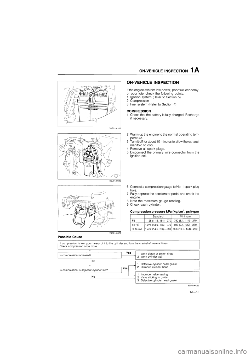
ON-VEHICLE INSPECTION
If the engine exhibits low power, poor fuel economy,
or poor idle, check the following points.
1. Ignition system (Refer to Section 5)
2. Compression
3. Fuel system (Refer to Section 4)
COMPRESSION
1. Check that the battery is fully charged. Recharge
if necessary.
76G01A-107
2. Warm up the engine to the normal operating tem-
perature.
3. Turn it off for about 10 minutes to allow the exhaust
manifold to cool.
4. Remove all spark plugs.
5. Disconnect the primary wire connector from the
ignition coil.
86U01X-020
6. Connect a compression gauge to No.
1
spark plug
hole.
7. Fully depress the accelerator pedal and crank the
engine.
8. Note the maximum gauge reading.
9. Check each cylinder.
Compression pressure kPa (kg/cm2, psi)-rpm
Standard Minimum
F6 1,128 (11.5, 164)—270 790 (8.1, 114)—270
F8-FE 1,275 (13.0, 185)—270 893 (9.1, 129)—270
FE 12-valve 1,422 (14.5, 206)—280 996 (10.2, 144)—280
76G01A-023
Possible Cause
86U01X-022
1A—13
Page 49 of 1865

ON-VEHICLE MAINTENANCE (TIMING BELT) 1 A
76G01A-027
76G01B-024
76G01A-028
/Jf
ry.
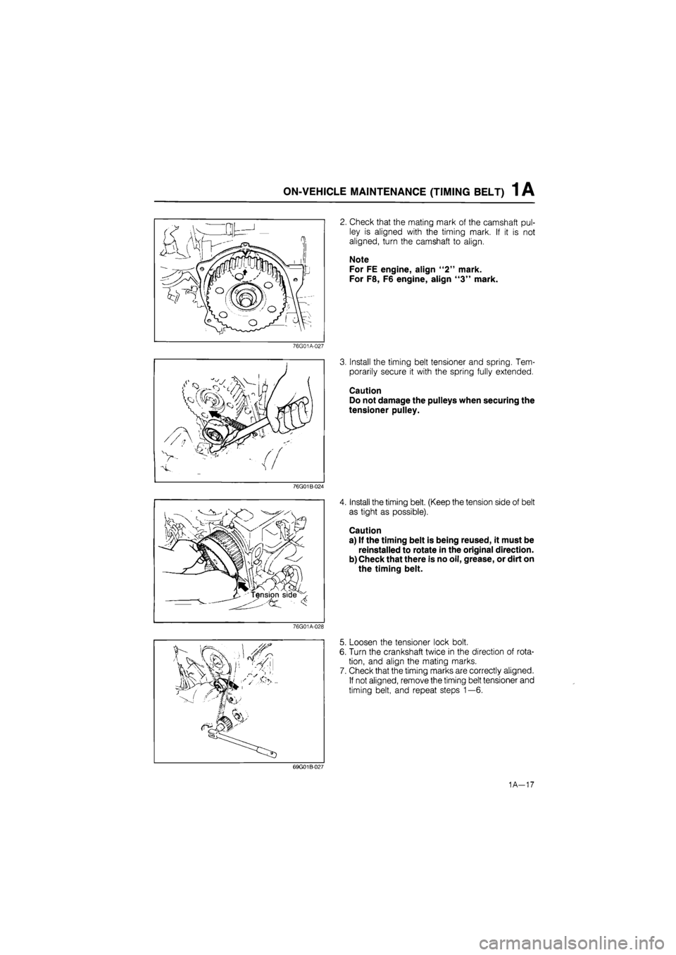
2. Check that the mating mark of the camshaft pul-
ley is aligned with the timing mark. If it is not
aligned, turn the camshaft to align.
Note
For FE engine, align "2" mark.
For F8, F6 engine, align "3" mark.
3. Install the timing belt tensioner and spring. Tem-
porarily secure it with the spring fully extended.
Caution
Do not damage the pulleys when securing the
tensioner pulley.
4. Install the timing belt. (Keep the tension side of belt
as tight as possible).
Caution
a) If the timing belt is being reused, it must be
reinstalled to rotate in the original direction.
b) Check that there is no oil, grease, or dirt on
the timing belt.
5. Loosen the tensioner lock bolt.
6. Turn the crankshaft twice in the direction of rota-
tion, and align the mating marks.
7. Check that the timing marks are correctly aligned.
If not aligned, remove the timing belt tensioner and
timing belt, and repeat steps 1—6.
69G01B-027
1A-17
Page 95 of 1865

ASSEMBLY (CYLINDER BLOCK) 1 A
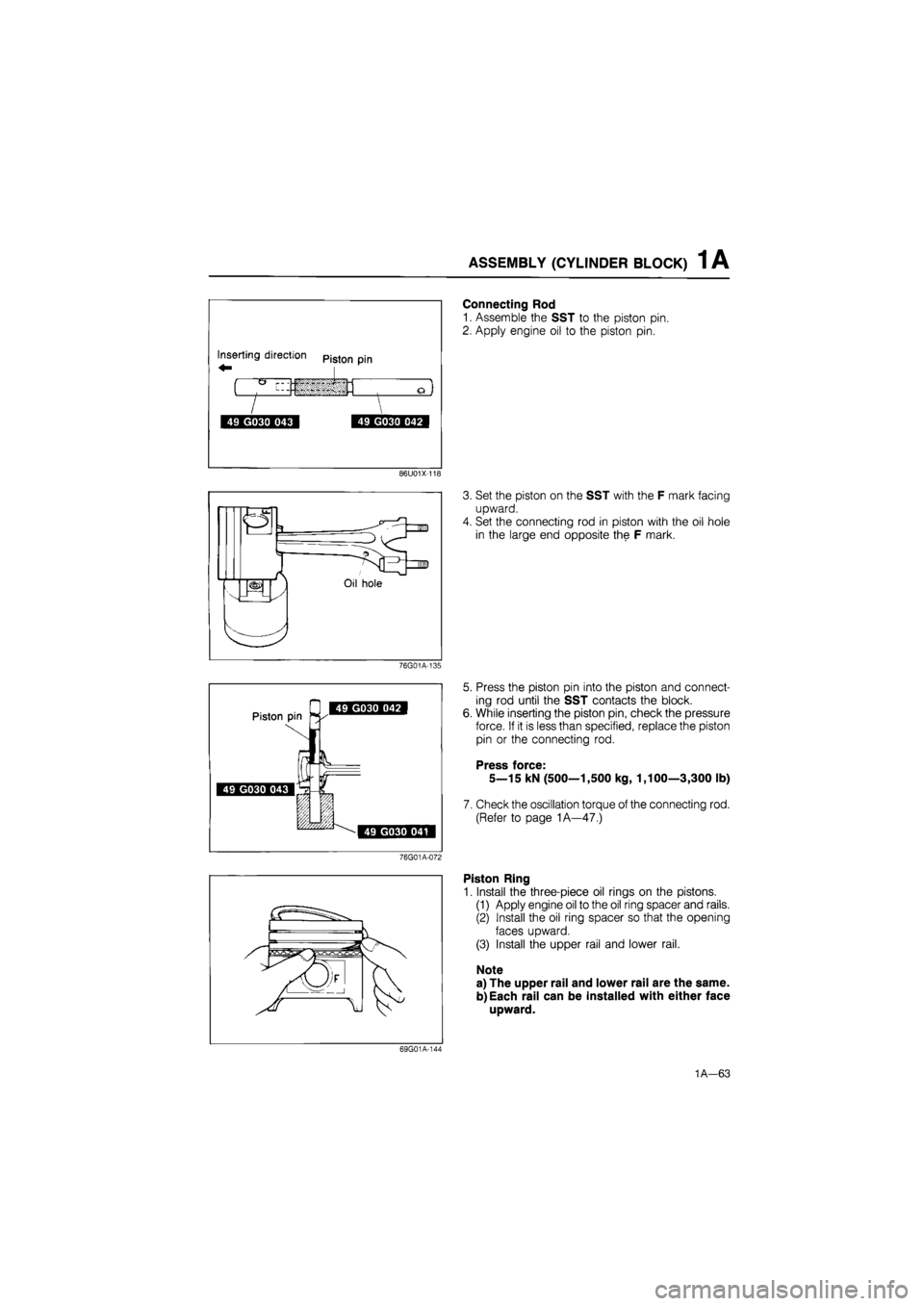
Connecting Rod
1. Assemble the SST to the piston pin.
2. Apply engine oil to the piston pin.
86U01X-118
3. Set the piston on the SST with the F mark facing
upward.
4. Set the connecting rod in piston with the oil hole
in the large end opposite the F mark.
76G01A-135
5. Press the piston pin into the piston and connect-
ing rod until the SST contacts the block.
While inserting the piston pin, check the pressure
force. If it is less than specified, replace the piston
pin or the connecting rod.
Press force:
5—15 kN (500—1,500 kg, 1,100—3,300 lb)
Check the oscillation torque of the connecting rod.
(Refer to page 1A—47.)
76G01A-072
Piston Ring
1. Install the three-piece oil rings on the pistons.
(1) Apply engine oil to the oil ring spacer and rails.
(2) Install the oil ring spacer so that the opening
faces upward.
(3) Install the upper rail and lower rail.
Note
a) The upper rail and lower rail are the same.
b) Each rail can be installed with either face
upward.
69G01A-144
1A—63
Page 96 of 1865
1 A ASSEMBLY (CYLINDER BLOCK)
Spacer iang
Oil ring
spacer ends
Upper rail
Piston
Lower rail
69G01A-145
86U01X-121
Oil ring —
upper rail f .Top ring
Oil ring (
spacer r \30° \ . Pistion
^-^/ao0F pin
Oil ring
lower rail /Second ring
69G01A-147
2. Check that both rails are expanded by the spacer
tangs as shown in the figure by checking that both
rails turn smoothly in both directions.
3. Install the second ring to the piston first, then in-
stall the top ring. Use a piston ring expander.
Caution
The rings must be installed with the "R"
marks facing upward.
4. Apply a liberal amount of clean engine oil to the
second and top piston rings.
5. Position the opening of each ring as shown in the
figure.
Crankshaft
1. Before installing the crankshaft, inspect the main
bearing oil clearances as described.
Note
The bearing with thrust shoulders is the cen-
ter bearing in the cylinder block.
86U01X-136
1A—64
Page 98 of 1865

1 A ASSEMBLY (CYLINDER BLOCK)
76G01A-074
86U01X-216
86U01X-127
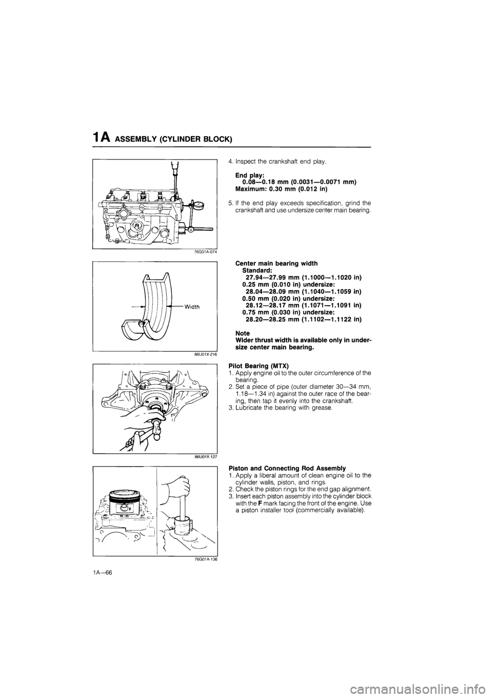
4. Inspect the crankshaft end play.
End play:
0.08—0.18 mm (0.0031—0.0071 mm)
Maximum: 0.30 mm (0.012 in)
5. If the end play exceeds specification, grind the
crankshaft and use undersize center main bearing.
Center main bearing width
Standard:
27.94—27.99 mm (1.1000—1.1020 in)
0.25 mm (0.010 in) undersize:
28.04—28.09 mm (1.1040—1.1059 in)
0.50 mm (0.020 in) undersize:
28.12—28.17 mm (1.1071—1.1091 in)
0.75 mm (0.030 in) undersize:
28.20—28.25 mm (1.1102—1.1122 in)
Note
Wider thrust width is available only in under-
size center main bearing.
Pilot Bearing (MTX)
1. Apply engine oil to the outer circumference of the
bearing.
2. Set a piece of pipe (outer diameter 30—34 mm,
1.18—1.34 in) against the outer race of the bear-
ing, then tap it evenly into the crankshaft.
3. Lubricate the bearing with grease.
Piston and Connecting Rod Assembly
1. Apply a liberal amount of clean engine oil to the
cylinder walls, piston, and rings.
2. Check the piston rings for the end gap alignment.
3. Insert each piston assembly into the cylinder block
with the F mark facing the front of the engine. Use
a piston installer tool (commercially available).
76G01A-136
1A—66