Page 1257 of 1865
9 FRONT AXLE
69G09X-011
•f SB. .j—
"V
jb
rCf?^
^ T
-U
• - ^
69G09X-012
76G09X-002
FRONT AXLE
ON-VEHICLE MAINTENANCE
Wheel Bearing Play
1. Jack up the vehicle and support it with safety
stands.
2. Check that there is no abnormal noise and that the
tire rotates smoothly when rotated by hand.
3. Remove the wheel.
4. Remove the caliper assembly and suspend it us-
ing a rope.
5. Position a dial indicator against the hub cap, then
push and pull the front wheel hub by hand in the
axial direction and measure the end play of the
wheel bearing.
If the end play exceeds specification, replace the
wheel bearing.
End play: 0.2 mm (0.0079 in) max
6. Install the caliper assembly.
Tightening torque: 78—98
N
m
(8.0—10.0 m-kg, 58—72 ft-lb)
7. Install the wheel.
Tightening torque: 88—118
N
m
(9.0—12.0 m-kg, 65—87 ft-lb)
86U09X-008
9—8
Page 1265 of 1865
9 REAR AXLE
86U09X-027
69G09X-012
76G09X-003
REAR AXLE
ON-VEHICLE MAINTENANCE
Wheel Bearing Play
1.Jack up the vehicle and support it with safety
stands.
2. Check that there is no abnormal noise and that the
tire rotates smoothly when rotated by hand.
3. Remove the wheel.
4. Remove the caliper assembly and suspend it us-
ing a rope.
5. Position a dial indicator against the hub cap, then
push and pull the front wheel hub or brake drum
by hand in the axial direction and measure the end
play of the wheel bearing.
If the end play exceeds specification, replace the
wheel bearing.
End play: 0.2 mm (0.0079 in) max.
6. Install the caliper assembly. (Disc)
Tightening torque: 45—67 N-m
(4.6—6.8 m-kg, 33—49 ft-lb)
7. Install the wheel.
Tightening torque: 88—118 N-m
(9.0—12.0 m-kg, 65—87 ft-lb)
86U09X-029
9—16
Page 1277 of 1865
9 DRIVESHAFT
86U09X-088
DRIVESHAFT
ON-VEHICLE MAINTENANCE
Boot
Check the boots on the driveshaft for cracks, dam-
age, grease leakage or loose boot bands. Replace
if necessary.
Spline Looseness
Turn the driveshaft by hand and check that the spline
and joint are not excessively loose.
Replace if necessary.
86U09X-089
Twisted or Cracked
Check that the driveshaft is not twisted or cracked.
Replace if necessary.
86U09X-090
9-28
Page 1289 of 1865

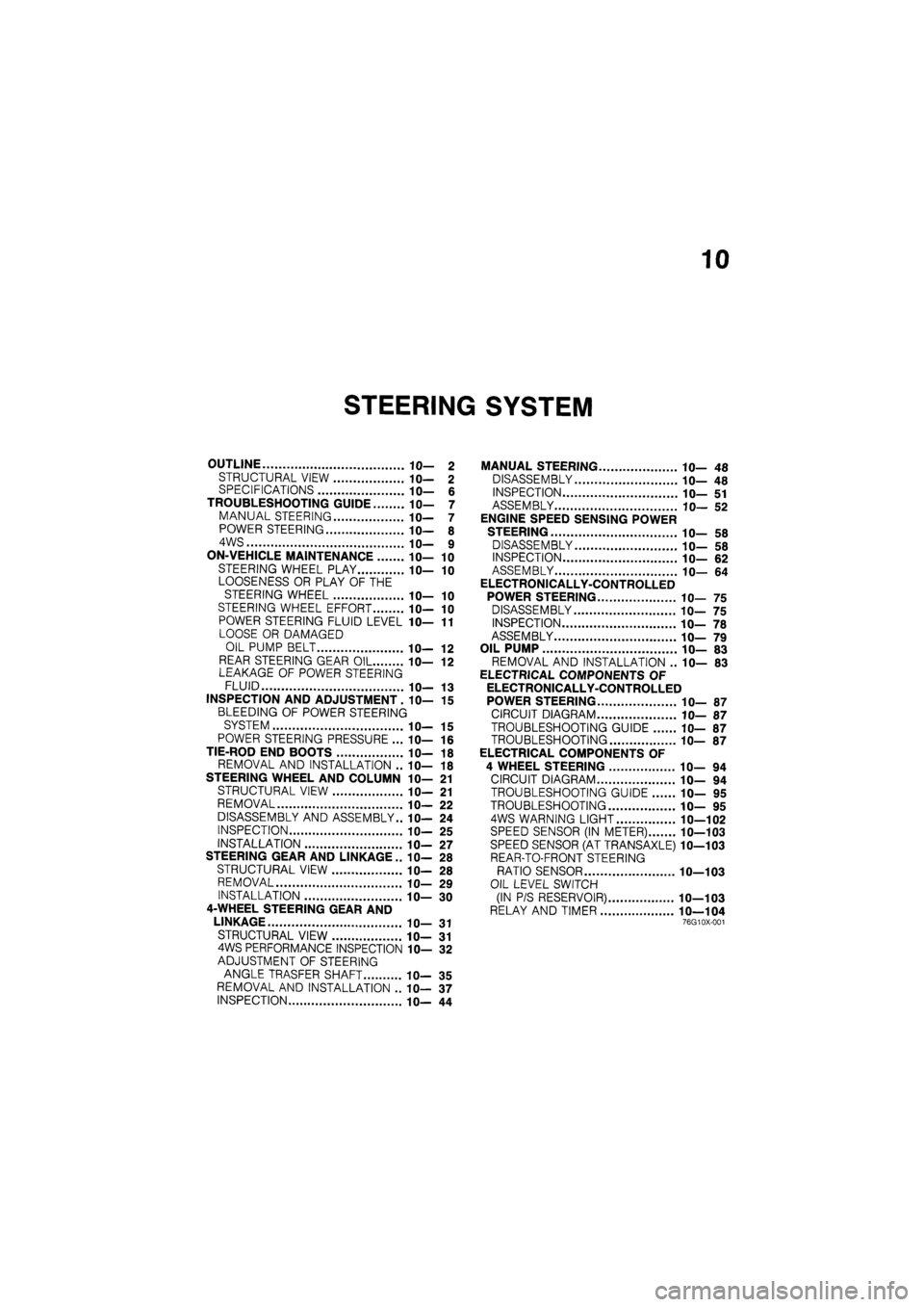
10
STEERING SYSTEM
OUTLINE 10— 2
STRUCTURAL VIEW 10— 2 SPECIFICATIONS 10— 6
TROUBLESHOOTING GUIDE 10— 7
MANUAL STEERING 10— 7
POWER STEERING 10— 8
4WS 10— 9
ON-VEHICLE MAINTENANCE 10— 10
STEERING WHEEL PLAY 10— 10
LOOSENESS OR PLAY OF THE
STEERING WHEEL 10— 10
STEERING WHEEL EFFORT 10— 10
POWER STEERING FLUID LEVEL 1 fl-11
LOOSE OR DAMAGED
OIL PUMP BELT IC— 12
REAR STEERING GEAR OIL 10— 12 LEAKAGE OF POWER STEERING
FLUID 10— 13
INSPECTION AND ADJUSTMENT. 10— 15
BLEEDING OF POWER STEERING
SYSTEM 10— 15
POWER STEERING PRESSURE ... 10— 16
TIE-ROD END BOOTS 10— 18
REMOVAL AND INSTALLATION .. 10— 18
STEERING WHEEL AND COLUMN 10— 21
STRUCTURAL VIEW 10— 21
REMOVAL 10— 22
DISASSEMBLY AND ASSEMBLY.. 10— 24
INSPECTION 10— 25
INSTALLATION 1 fl-27
STEERING GEAR AND LINKAGE .. IC— 28
STRUCTURAL VIEW 10— 28
REMOVAL 10— 29
INSTALLATION 10— 30
4-WHEEL STEERING GEAR AND
LINKAGE 10— 31
STRUCTURAL VIEW 10— 31 4WS PERFORMANCE INSPECTION 10— 32
ADJUSTMENT OF STEERING
ANGLE TRASFER SHAFT 10— 35
REMOVAL AND INSTALLATION .. 10— 37
INSPECTION 10— 44
MANUAL STEERING 10— 48
DISASSEMBLY 10— 48
INSPECTION 10— 51
ASSEMBLY 10— 52
ENGINE SPEED SENSING POWER
STEERING 10— 58
DISASSEMBLY 10— 58
INSPECTION 10— 62
ASSEMBLY 10— 64
ELECTRONICALLY-CONTROLLED
POWER STEERING 10— 75
DISASSEMBLY 10— 75
INSPECTION 10— 78
ASSEMBLY 10— 79
OIL PUMP 10— 83
REMOVAL AND INSTALLATION .. 10— 83
ELECTRICAL COMPONENTS OF
ELECTRONICALLY-CONTROLLED
POWER STEERING 10— 87
CIRCUIT DIAGRAM 10— 87
TROUBLESHOOTING GUIDE 10— 87
TROUBLESHOOTING 10— 87
ELECTRICAL COMPONENTS OF
4 WHEEL STEERING 10— 94
CIRCUIT DIAGRAM 10— 94
TROUBLESHOOTING GUIDE 10— 95
TROUBLESHOOTING 10— 95
4WS WARNING LIGHT 10—102
SPEED SENSOR (IN METER) 10—103
SPEED SENSOR (AT TRANSAXLE) 10—103
REAR-TO-FRONT STEERING
RATIO SENSOR 10—103
OIL LEVEL SWITCH
(IN P/S RESERVOIR) 10—103
RELAY AND TIMER 10—104 76G10X-001
Page 1298 of 1865

1 0 ON-VEHICLE MAINTENANCE
86U10X-010
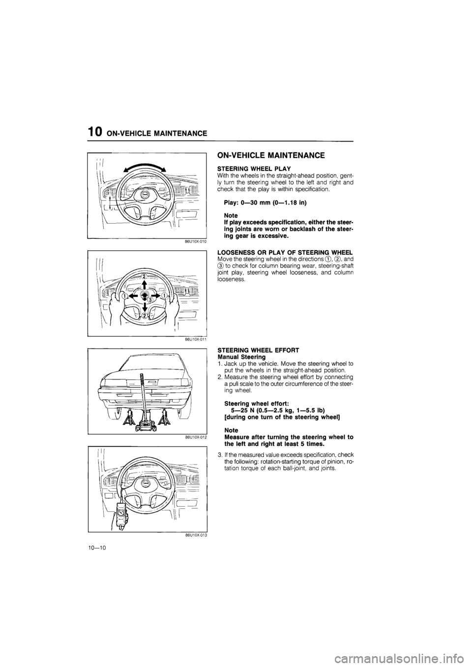
ON-VEHICLE MAINTENANCE
STEERING WHEEL PLAY
With the wheels in the straight-ahead position, gent-
ly turn the steering wheel to the left and right and
check that the play is within specification.
Play: 0—30 mm (0—1.18 in)
Note
If play exceeds specification, either the steer-
ing joints are worn or backlash of the steer-
ing gear is excessive.
LOOSENESS OR PLAY OF STEERING WHEEL
Move the steering wheel in the directions ©, ©, and
© to check for column bearing wear, steering-shaft
joint play, steering wheel looseness, and column
looseness.
86U10X-011
86U10X-012
STEERING WHEEL EFFORT
Manual Steering
1. Jack up the vehicle. Move the steering wheel to
put the wheels in the straight-ahead position.
2. Measure the steering wheel effort by connecting
a pull scale to the outer circumference of the steer-
ing wheel.
Steering wheel effort:
5—25 N (0.5—2.5 kg, 1—5.5 lb)
[during one turn of the steering wheel]
Note
Measure after turning the steering wheel to
the left and right at least 5 times.
3. If the measured value exceeds specification, check
the following: rotation-starting torque of pinion, ro-
tation torque of each ball-joint, and joints.
86U10X-013
10—10
Page 1299 of 1865

ON-VEHICLE MAINTENANCE 1 0
"{krf
'"""^JlW^M 1
V
^A-X
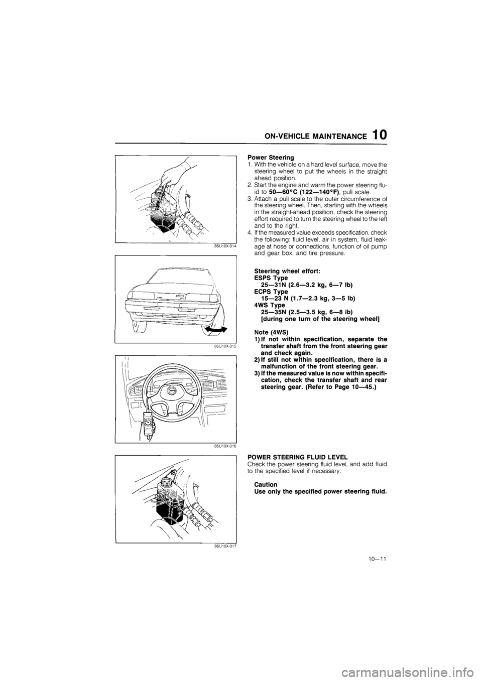
Power Steering
1.
86U10X-014
86U10X-015
With the vehicle on a hard level surface, move the
steering wheel to put the wheels in the straight
ahead position.
Start the engine and warm the power steering flu-
id to 50—60°C (122—140°F), pull scale.
Attach a pull scale to the outer circumference of
the steering wheel. Then, starting with the wheels
in the straight-ahead position, check the steering
effort required to turn the steering wheel to the left
and to the right.
If the measured value exceeds specification, check
the following: fluid level, air in system, fluid leak-
age at hose or connections, function of oil pump
and gear box, and tire pressure.
Steering wheel effort:
ESPS Type
25—31N (2.6—3.2 kg, 6—7 lb)
ECPS Type
15—23 N (1.7—2.3 kg, 3—5 lb)
4WS Type
25—35N (2.5—3.5 kg, 6—8 lb)
[during one turn of the steering wheel]
Note (4WS)
1)lf not within specification, separate the
transfer shaft from the front steering gear
and check again.
2) If still not within specification, there is a
malfunction of the front steering gear.
3) If the measured value is now within specifi-
cation, check the transfer shaft and rear
steering gear. (Refer to Page 10—45.)
86U10X-016
POWER STEERING FLUID LEVEL
Check the power steering fluid level, and add fluid
to the specified level if necessary.
Caution
Use only the specified power steering fluid.
86U10X-017
10—11
Page 1300 of 1865

1 0 ON-VEHICLE MAINTENANCE
Gasoline engine Adjust bolt
Idler pulley fM ,.. Lock nut
1 / I
Drive pulley Power steering oil
pump pulley
76G10X-004
Diesel engine
Vacuum pump
Rear
camshaft
pulley
Power steering oil
pump pulley
76G10X-005
86U10X-019
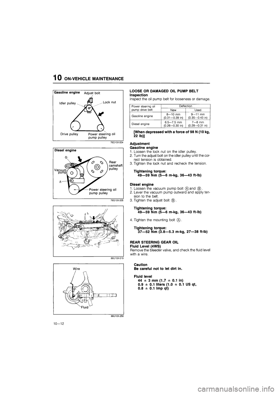
LOOSE OR DAMAGED OIL PUMP BELT
Inspection
Inspect the oil pump belt for looseness or damage.
Power steering
oil
pump drive belt
Deflection Power steering
oil
pump drive belt New Used
Gasoline engine 8—10
mm
(0.31-0.39
in)
9—11
mm
(0.35—0.43
in)
Diesel engine 6.5—7.5
mm
(0.26—0.30
in)
7—8
mm
(0.28—0.31
in)
[When depressed with a force of 98 N (10 kg,
22 lb)]
Adjustment
Gasoline engine
1. Loosen the lock nut on the idler pulley.
2. Turn the adjust bolt on the idler pulley until the cor-
rect tension is obtained.
3. Tighten the lock nut and recheck the tension.
Tightening torque:
49—59 Nm (5—6 m-kg, 36—43 ft-lb)
Diesel engine
1. Loosen the vacuum pump bolt ©and (B).
2. Lever the vacuum pump outward and apply ten-
sion to the belt.
3. Tighten the adjust bolt (|).
Tightening torque:
49—59
N
m (5—6 m-kg, 36—43 ft-lb)
4. Tighten the mounting bolt
Tightening torque:
37—52 N-m (3.8—5.3 m-kg, 27—38 ft-lb)
REAR STEERING GEAR OIL
Fluid Level (4WS)
Remove the bleeder valve, and check the fluid level
with a wire.
Caution
Be careful not to let dirt in.
Fluid level
44 ± 3 mm (1.7 ± 0.1 in)
0.9 ± 0.1 liters (1.0 ± 0.1 US qt,
0.8 ± 0.1 Imp qt)
86U10X-250
10-12
Page 1301 of 1865
ON-VEHICLE MAINTENANCE 1 0
LEAKAGE OF POWER STEERING FLUID
Check the following points for fluid leakage:
1. Gear
2. Oil pump
3. All fluid pipes and connections
4. Solenoid valve (ECPS Type, 4WS Type)
Note
a) Start the engine, and check for fluid leakage after turning the steering wheel completely
to the left and right to apply fluid pressure. Do not, however, keep the steering wheel
in the fully turned position for more than 15 seconds.
b)The points where fluid leakage may occur are indicated by the arrows in the figure.
Power Steering (2WS)
86U10X-020
10-13