Page 791 of 878
193
S 6 SEAT HEATER SW
4±GROUND : APPROX. 12 VOLTS WITH IGNITION SW AT ON POSITION
1±GROUND : ALWAYS CONTINUOUS
: PARTS LOCATION
CODESEE PAGECODESEE PAGECODESEE PAGE
S 629S1331S1531
S1231S1431
: JUNCTION BLOCK AND WIRE HARNESS CONNECTOR
CODESEE PAGEJUNCTION BLOCK AND WIRE HARNESS (CONNECTOR LOCATION)
1H20COWL WIRE AND J/B NO. 1 (LEFT KICK PANEL)
: CONNECTOR JOINING WIRE HARNESS AND WIRE HARNESS
CODESEE PAGEJOINING WIRE HARNESS AND WIRE HARNESS (CONNECTOR LOCATION)
IC136FLOOR NO. 2 WIRE AND COWL WIRE (LEFT KICK PANEL)
BQ142FLOOR NO. 2 WIRE AND SEAT WIRE (UNDER THE FRONT LH SEAT)
: GROUND POINTS
CODESEE PAGEGROUND POINTS LOCATION
IG36RIGHT KICK PANEL
BI40LEFT QUARTER PILLAR
: SPLICE POINTS
CODESEE PAGEWIRE HARNESS WITH SPLICE POINTSCODESEE PAGEWIRE HARNESS WITH SPLICE POINTS
I1138COWL WIREB 942SEAT WIRE
I2438COWL WIRE
1246
12 12 S6BLACKS14 S15 S13BLUE S12BLUE
12
3412
34
SERVICE HINTS
Page 842 of 878

Junction Block (The number in the circle is the
J/B No. and connector code is shown beside
it). Junction Blocks are shaded to clearly
separate them from other parts (different junc-
tion blocks are shaded differently for further
clarification.).
Example:
Indicates related system.
Indicates the wiring harness and wiring har-
ness connector. The wiring harness with male
terminal is shown with arrows
Outside numerals are pin numbers.
is used to indicate different wiring and
connector, etc. when the vehicle model, engine
type, or specification is different.
Indicates a shielded cable.
Indicates and located on ground point.
The same code occuring on the next page
indicates that the wire harness is continuous. System Title
Indicates the wiring color.
Wire colors are indicated by an alphabetical code.
B = Black L = Blue R = Red
BR = Brown LG = Light Green V = Violet
G = Green O = Orange W = White
GR = Gray P = Pink Y = Yellow
The first letter indicates the basic wire color and
the second letter indicates the color of the stripe.
Indicates the connector to be connected to a
part (the numeral indicates the pin No.)
The position of the parts is the same as shown
in the wiring diagram and wire routing.
Indicates the pin number of the connector.
The numbering system is different for female
and male connectors.
The numbering system for the overall wiring dia-
gram is the same as above.
Indicates a Relay Block. No Shading is used and
only the Relay Block No. is shown to distinguish
it from the J/B.
247
Page 865 of 878

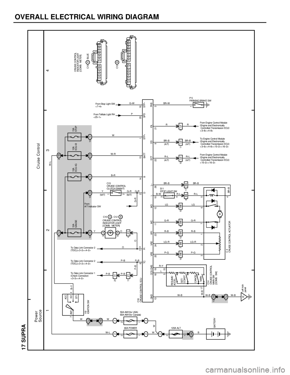
OVERALL ELECTRICAL WIRING DIAGRAM
1
234
17 SUPRA
7ACC
IG1
ST 1 AM1 4
1J 41J 5
221B 41E 12 1H12 1I9
21 I I1
11 I F1 4 IF22 1 9A
6B
IE 1H 13
1J 116 I B6 7 IB6 10 IB6 9 IB6 15 I B6
8IB6 17IB64 3
M10IJ2 11IJ2 3IJ1
1 1H 81I10 1B 2WW
W± LP± B P± BP±BO YOYB±R W± RW
L R±YP± G LG±RR± B G±RLG B±WBR± B
P±BO G±R
W± B P±G LG±RR± B G± RLGR±L BR± B
W± B W± B
B
P±B O G±R
W±B
BR± B 13 18 19 25 24 23 11 12 10 26 22
3217 65 515
1787 2 14 15 1
4
R± L
921 3
R± L BR±BR
R±L BR± BR BR±W
W± L
B±Y
I19
IGNITION SW10A
GAUGE10A
ECU±IG
CRUISE CONTROL
I NDI CA TOR L I GHT
[COMB. METER]C1 5
CRUI S E CONTROL
CL UTCH S W(
M/T)
TC PI D B BATT
GND CCS CMS VR3 VR2 VR1 MC MO L L±
60A POWER 50A AM1(
for USA)
60A AM1(
for Canada)
120A ALTBATTERYRESUME/
ACCEL
SET/
COAST
CANCEL
MAIN
C1 4
CRUI S E CONTROL
MA I N SW
[COMB. SW]
Left kick
panelC4
CRUISE CONTROL ACTUATOR10A
ECU±B15A
STOP
ST P+
ECT OD IDL PKB
S1 1
STOP LIGHT SWP5
PARKING BRAKE SW
C10 A , C12 B
2A 1
Fr om Telltale Light RH
< 25±1>From Stop Light SW
<7±4>20
SPD STP±16P G±W
13 9 8 7 6 5 4 3 2 1 101112
16 11 10 9 8 5 4 3 2 112131467 15B C12A C10 BLUE CRUISE CONTROL
I NDI CA TOR L I GHT
[COMB. METER]
C16
CRUISE CONTROL ECU
From Engine Contr ol Module
(
Engine and Electronically
Controlled Transmission ECU)
< 15±2> < 16±2> To Engine Contr ol Module
(
Engine and Electronically
Controlled Transmission ECU)
<3±6><4±8><15±2><16±2> From Engine Contr ol Module
(
Engine and Electronically
Controlled Transmission ECU)
< 3±8> < 4±8>
1 11
2 22
To Dat a Link Connect or 1
(
Chec k Connect or)
<3±3><4±2> To Dat a Link Connect or 2
(
TDCL)
<3±2><4±2>
To Dat a Link Connect or 2
(
TDCL)
<3±2><4±2>Fro m
A/ T Indicat or SW
2 2W
Power
SourceCruise Control2
W
G± R
(
M/ T)(
M/T)(
A/T) (
A/T)
(
A/ T) (
A/ T)
Page 867 of 878

OVERALL ELECTRICAL WIRING DIAGRAM
1234
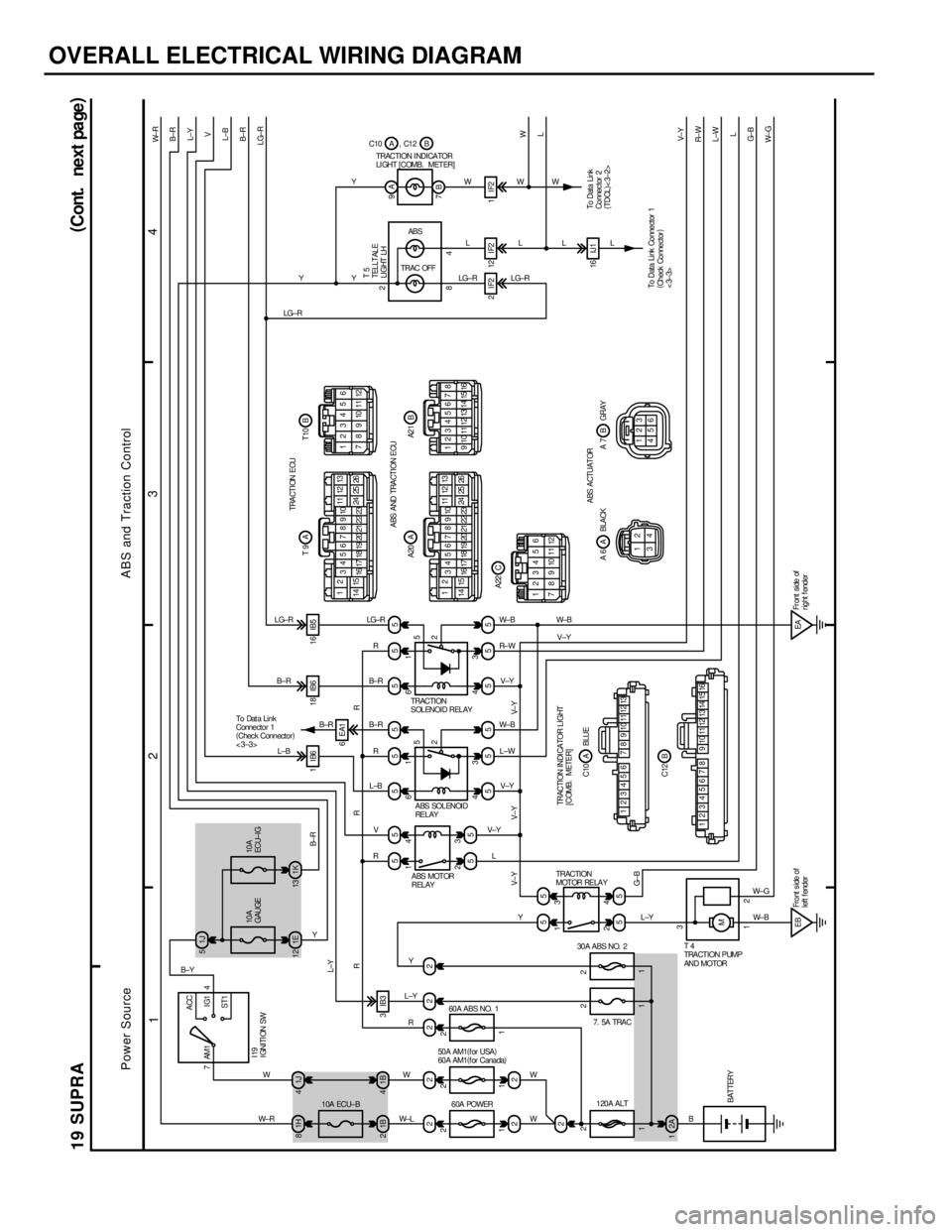
19 SUPRA
7ACC
IG1
ST1 AM1 4
1H 81J41J 5
22 22255 5 55 5 55
55 1B 21B41E 12 1K13
55
555 5551IB6 18IB6 16IB5
3 4
2 1
4 6
3 1
2
2A55
EBM4 3
2 1
EA9A
7B
2 IF2 12 IF2 1 IF2
16 IJ 1 5
45
2
3 61
To Data Link Connector 1
(
Check Connector)
<3±3>To Data Link
Connec tor 2
(
TDCL)
<3±2> T5
TELLTALE
LIGHT LH
ABS
TRAC OFF TRACTION I NDICATOR
LI GHT [ COMB. MET ER]
I19
IGNITION SW10A
GAUGE10A
ECU± I G
10A ECU±B30A ABS NO. 2
50A AM1(
for USA)
60A AM1(
f or Canada)
60A POWER 60A ABS NO. 1
120A ALT 7. 5A TRACBATTERY
T4
TRACTION PUMP
AND MOTOR A BS MOT OR
RELAYABS SOLENOID
RE L AY TRACTION
SOLENOID RELAY
TRACTION
MOTOR RELAY
TRACTION INDI CATOR L IGHT
[COMB. METER]
13 9 8 7 6 5 4 3 2 1 101112
16 11 10 9 8 5 4 3 2 112131467 15A C10 BLUE
B C12TRACTION ECU
12
34567891011 12 13
14 15
16 17 18 19 20 21 22 2324 25 26123456
7 8 9 10 11 12 A T9 BT10
ABS AND TRACTION ECU
123456
7 8 9 10 11 12C A22 12
34567891011 12 13
14 15
16 17 18 19 20 21 22 2324 25 26 A A20
12345678
9 10111213141516B A2 1
ABS ACTUATOR
2 1
34123
456 A A 6 BLACK BA7 GRAY
To Dat a Li n k
Connector 1
(
Chec k Connector)
<3±3>
W± R
B±R
L±Y
V
L±B
B±R
LG±R
W
L
V± Y
R± W
L±W
L
G± B
W± G RR
V±Y V±Y V±YB±R
L±Y
R
Y
L±Y
W
W±LL V± YV±Y L±W W± BV±Y R± W W± B
W± RWYB± RR LG±R
B± R
R
L±B
V
R L±B B±R LG±R
B±YYL±YW±B
B V±Y W±B Y Y
Y
LG±RLG±RL WWW
L L
LG±RL
W± G
R
Fr ont side of
r ight f ender Fro nt s i de o f
left f enderG±B 22
2 22
2
3 1 11
1 11
1284 2
(
Cont. next pa ge)
16EA1
B±RC10 A , C12 B
3IB3
2 22
W W
Power SourceABS and Traction Control