Page 2597 of 3115
SS0O7-01
SS-18
- SERVICE SPECIFICATIONSIGNITION
158 Author�: Date�:
2004 LAND CRUISER (RM1071U)
TORQUE SPECIFICATION
Part tightenedN´mkgf´cmft´lbf
Spark plug x Cylinder head17.518013
Ignition coil (with igniter) x Cylinder head cover7.58066 in.´lbf
Camshaft position sensor x LH cylinder head7.58066 in.´lbf
Crankshaft position sensor x Oil pump6.56558 in.´lbf
Page 2647 of 3115

A07061
TOYOTA
Hand-Held
Tester
DLC3SF10V-02
B04440
Up
Pulsation
Damper
Screw
B04441
SST
(Gauge)SST
(Adaptor)
SST
(Union)
Front Fuel Pipe
Gasket
- SFIFUEL PUMP
SF-7
1706 Author�: Date�:
2004 LAND CRUISER (RM1071U)
FUEL PUMP
ON-VEHICLE INSPECTION
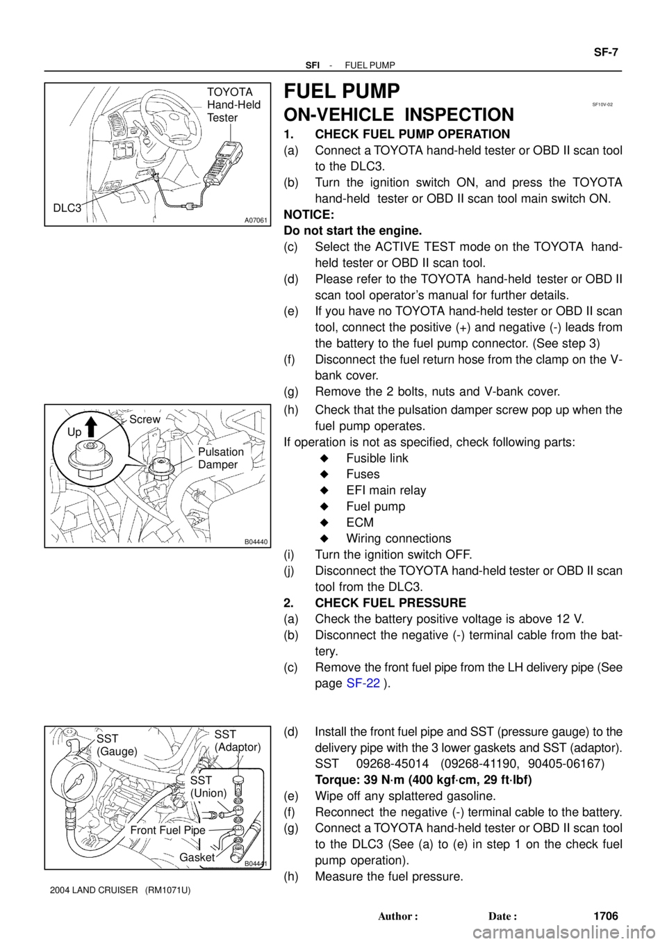
1. CHECK FUEL PUMP OPERATION
(a) Connect a TOYOTA hand-held tester or OBD II scan tool
to the DLC3.
(b) Turn the ignition switch ON, and press the TOYOTA
hand-held tester or OBD II scan tool main switch ON.
NOTICE:
Do not start the engine.
(c) Select the ACTIVE TEST mode on the TOYOTA hand-
held tester or OBD II scan tool.
(d) Please refer to the TOYOTA hand-held tester or OBD II
scan tool operator's manual for further details.
(e) If you have no TOYOTA hand-held tester or OBD II scan
tool, connect the positive (+) and negative (-) leads from
the battery to the fuel pump connector. (See step 3)
(f) Disconnect the fuel return hose from the clamp on the V-
bank cover.
(g) Remove the 2 bolts, nuts and V-bank cover.
(h) Check that the pulsation damper screw pop up when the
fuel pump operates.
If operation is not as specified, check following parts:
�Fusible link
�Fuses
�EFI main relay
�Fuel pump
�ECM
�Wiring connections
(i) Turn the ignition switch OFF.
(j) Disconnect the TOYOTA hand-held tester or OBD II scan
tool from the DLC3.
2. CHECK FUEL PRESSURE
(a) Check the battery positive voltage is above 12 V.
(b) Disconnect the negative (-) terminal cable from the bat-
tery.
(c) Remove the front fuel pipe from the LH delivery pipe (See
page SF-22).
(d) Install the front fuel pipe and SST (pressure gauge) to the
delivery pipe with the 3 lower gaskets and SST (adaptor).
SST 09268-45014 (09268-41190, 90405-06167)
Torque: 39 N´m (400 kgf´cm, 29 ft´lbf)
(e) Wipe off any splattered gasoline.
(f) Reconnect the negative (-) terminal cable to the battery.
(g) Connect a TOYOTA hand-held tester or OBD II scan tool
to the DLC3 (See (a) to (e) in step 1 on the check fuel
pump operation).
(h) Measure the fuel pressure.
Page 2657 of 3115

B00884
SST
(Adaptor)
SST
(Hose)
SST
(Clamp)
Vinyl
HoseO-Ring
A07061
TOYOTA
Hand-Held
Tester
DLC3
B00883
ConnectSST
(Wire)
A01293
- SFIINJECTOR
SF-25
1724 Author�: Date�:
2004 LAND CRUISER (RM1071U)
(h) Install the O-ring to the injector.
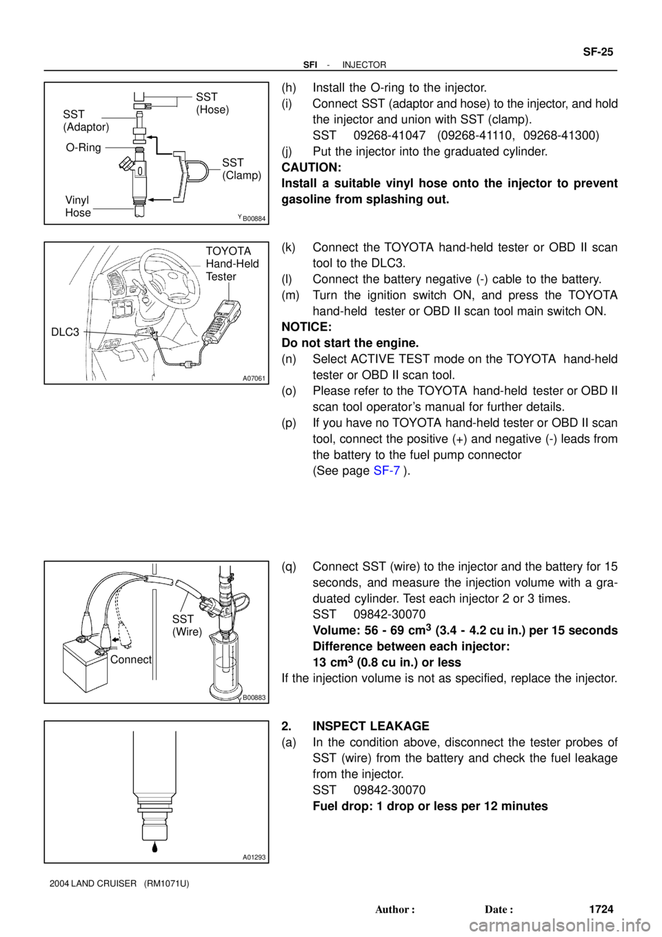
(i) Connect SST (adaptor and hose) to the injector, and hold
the injector and union with SST (clamp).
SST 09268-41047 (09268-41110, 09268-41300)
(j) Put the injector into the graduated cylinder.
CAUTION:
Install a suitable vinyl hose onto the injector to prevent
gasoline from splashing out.
(k) Connect the TOYOTA hand-held tester or OBD II scan
tool to the DLC3.
(l) Connect the battery negative (-) cable to the battery.
(m) Turn the ignition switch ON, and press the TOYOTA
hand-held tester or OBD II scan tool main switch ON.
NOTICE:
Do not start the engine.
(n) Select ACTIVE TEST mode on the TOYOTA hand-held
tester or OBD II scan tool.
(o) Please refer to the TOYOTA hand-held tester or OBD II
scan tool operator's manual for further details.
(p) If you have no TOYOTA hand-held tester or OBD II scan
tool, connect the positive (+) and negative (-) leads from
the battery to the fuel pump connector
(See page SF-7).
(q) Connect SST (wire) to the injector and the battery for 15
seconds, and measure the injection volume with a gra-
duated cylinder. Test each injector 2 or 3 times.
SST 09842-30070
Volume: 56 - 69 cm
3 (3.4 - 4.2 cu in.) per 15 seconds
Difference between each injector:
13 cm
3 (0.8 cu in.) or less
If the injection volume is not as specified, replace the injector.
2. INSPECT LEAKAGE
(a) In the condition above, disconnect the tester probes of
SST (wire) from the battery and check the fuel leakage
from the injector.
SST 09842-30070
Fuel drop: 1 drop or less per 12 minutes
Page 2658 of 3115
SF-26
- SFIINJECTOR
1725 Author�: Date�:
2004 LAND CRUISER (RM1071U)
(b) Turn the ignition switch OFF.
(c) Disconnect the negative (-) terminal cable from the bat-
tery.
(d) Remove SST and fuel tube connector.
SST 09268-41047, 09842-30070
(e) Disconnect the TOYOTA hand-held tester or OBD II scan
tool from the DLC3.
(f) Reconnect the fuel inlet pipe (fuel tube connector) to the
fuel filter.
CAUTION:
Perform connecting operations of the fuel tube connector
(quick type) after observing the precautions (See page
SF-1).
Page 2668 of 3115

SF0P2-07
B04431
B04890
OhmmeterE2
THA
B04891
Air VGE2G
Voltmeter
SF-32
- SFIMASS AIR FLOW (MAF) METER
1731 Author�: Date�:
2004 LAND CRUISER (RM1071U)
INSPECTION
1. DISCONNECT MAF METER CONNECTOR
2. REMOVE MAF METER
Remove the 2 screws and MAF meter.
3. INSPECT MAF METER
(a) Using an ohmmeter, measure the resistance between ter-
minals THA and E2.
TerminalsResistanceTemperature
THA - E212.5 - 16.9 kW-20°C (-4°F)
THA - E22.19 - 2.67 kW20°C (68°F)
THA - E20.50 - 0.68 kW60°C (140°F)
If the resistance is not as specified, replace the MAF meter.
(b) Inspect for operation.
(1) Connect the MAF meter connector.
(2) Connect the negative (-) terminal cable to the bat-
tery.
(3) Turn the ignition switch ON.
(4) Using a voltmeter, connect the positive (+) tester
probe to terminal VG and negative (-) tester probe
to terminal E2G.
(5) Blow air into the MAF meter, and check that the volt-
age fluctuates.
If operation is not as specified, replace the MAF meter.
(6) Turn the ignition switch OFF.
(7) Disconnect the negative (-) terminal cable from the
battery.
(8) Disconnect the MAF meter connector.
4. REINSTALL MAF METER
Install the MAF meter with the 2 screws.
Torque: 1.68 N´m (17 kgf´cm, 15 in.´lbf)
5. RECONNECT MAF METER CONNECTOR
Page 2669 of 3115

SF0XU-1 1
- SFISFI SYSTEM
SF-1
1700 Author�: Date�:
2004 LAND CRUISER (RM1071U)
SFI SYSTEM
PRECAUTION
1. BEFORE WORKING ON FUEL SYSTEM, DISCON-
NECT NEGATIVE (-) TERMINAL CABLE FROM BAT-
TERY
HINT:
Any diagnostic trouble code retained by the computer will be
erased when the negative (-) terminal cable is removed from
the battery.
Therefore, if necessary, read the diagnosis before removing the
negative (-) terminal cable from the battery.
2. DO NOT SMOKE OR WORK NEAR AN OPEN FLAME
WHEN WORKING ON THE FUEL SYSTEM
3. KEEP GASOLINE AWAY FROM RUBBER OR
LEATH-
ER PARTS
4. MAINTENANCE PRECAUTIONS
(a) Take following precautions to prevent the engine misfire.
(1) Check proper connection to battery terminals, etc.
(2) After repair work, check that the ignition coil termi-
nals and all other ignition system lines are recon-
nected securely.
(3) When cleaning the engine compartment, be espe-
cially careful to protect the electrical system from
water.
(b) Take following precautions to handle the oxygen sensor.
(1) Do not drop the oxygen sensor or hit against an ob-
ject.
(2) Do not allow the sensor to contact with water.
5. IF VEHICLE IS EQUIPPED WITH MOBILE RA-
DIO
SYSTEM (HAM, CB, ETC.)
If the vehicle is equipped with a mobile communication system,
refer to the precaution in the IN section.
6. AIR INDUCTION SYSTEM
(a) Separation of the engine oil dipstick, oil filler cap, PCV
hose, etc. may cause the engine to be out of tune.
(b) Disconnection, looseness or cracks in the parts of the air
induction system between the throttle body and cylinder
head will cause air suction, which makes the engine out
of tune.
7. ELECTRONIC CONTROL SYSTEM
(a) Disconnect the power by either turning the ignition switch
OFF or disconnecting the negative (-) terminal cable from
the battery before removing SFI wiring connectors, termi-
nals, etc.
HINT:
Always check the diagnostic trouble code before disconnecting
the negative (-) terminal cable from the battery.
(b) When installing the battery, be especially careful not to in-
correctly connect the positive (+) and negative (-) cables.
Page 2670 of 3115

FI2553
SST
B04902Fuel Pump Connector
Disconnect SF-2
- SFISFI SYSTEM
1701 Author�: Date�:
2004 LAND CRUISER (RM1071U)
(c) Do not a severe impact during removal or installation.
Handle all SFI parts carefully, especially the ECM.
(d) Be careful during the troubleshooting as there are numer-
ous transistor circuit, and even slight terminal contact can
cause further troubles.
(e) Do not open the ECM cover.
(f) When inspecting in rainy weather, take care to prevent
entry of water. Also, when washing the engine compart-
ment, prevent water from getting on the SFI parts and the
wiring connectors.
(g) Parts should be replaced as the original assembly.
(h) Care should be taken when pulling out and inserting the
wiring connectors.
(1) Release the lock and pull out the connector.
(2) Fully insert the connector and check that it is locked.
(i) Use SST for the inspection, the injector and the wiring
connector test.
SST 09842-30070
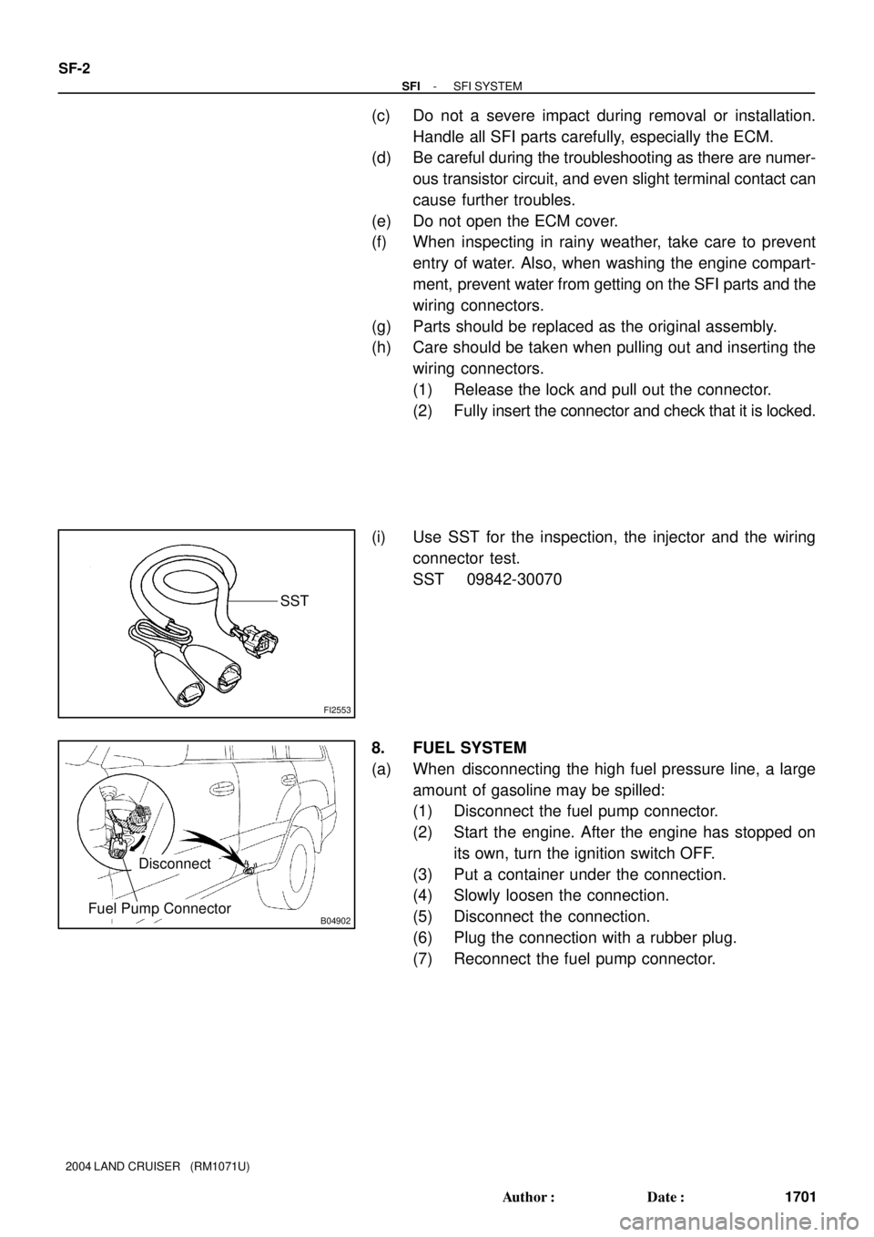
8. FUEL SYSTEM
(a) When disconnecting the high fuel pressure line, a large
amount of gasoline may be spilled:
(1) Disconnect the fuel pump connector.
(2) Start the engine. After the engine has stopped on
its own, turn the ignition switch OFF.
(3) Put a container under the connection.
(4) Slowly loosen the connection.
(5) Disconnect the connection.
(6) Plug the connection with a rubber plug.
(7) Reconnect the fuel pump connector.
Page 2673 of 3115

B04897
Push
B04896
Pull
A07061
TOYOTA
Hand-Held
Tester
DLC3
- SFISFI SYSTEM
SF-5
1704 Author�: Date�:
2004 LAND CRUISER (RM1071U)
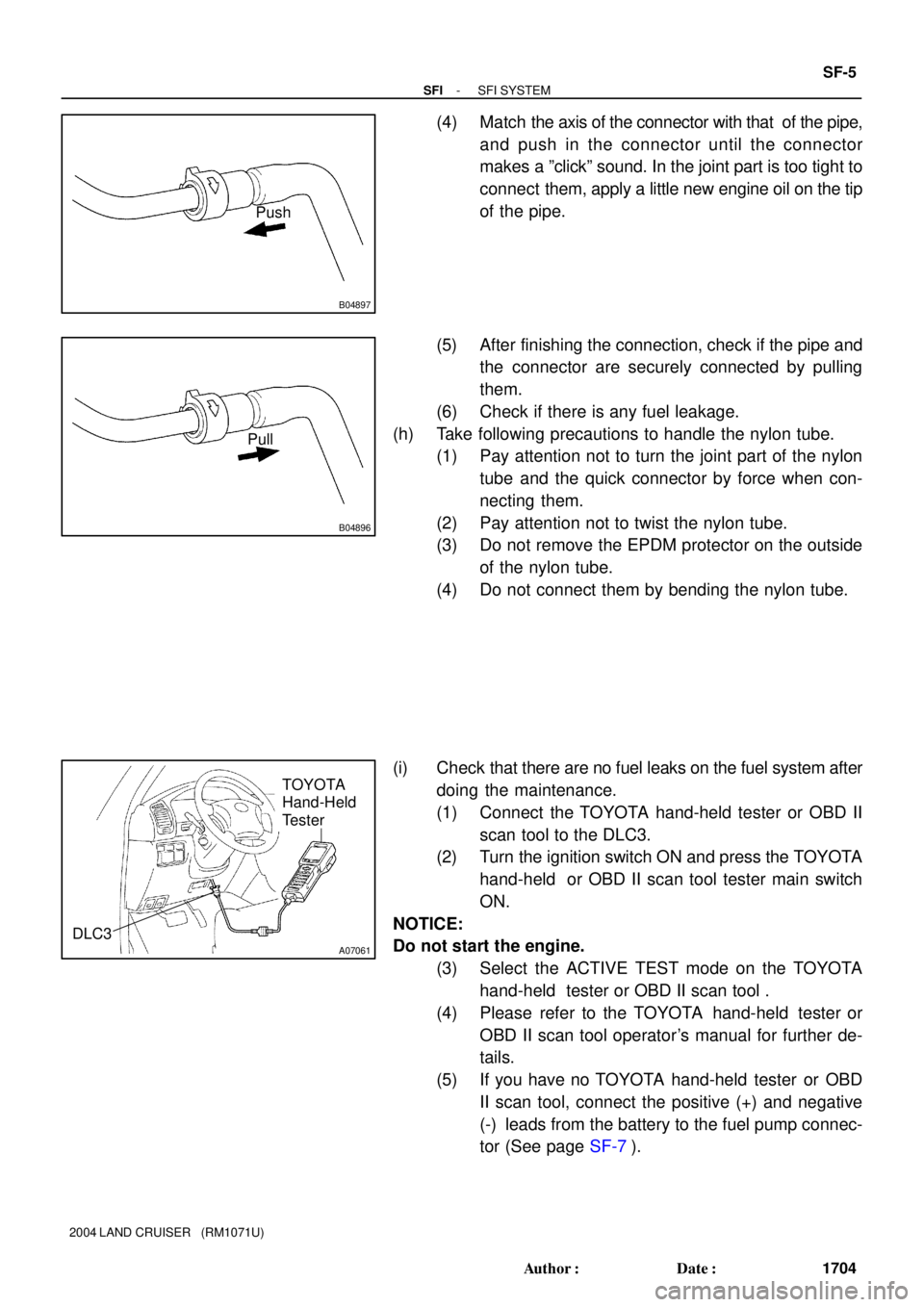
(4) Match the axis of the connector with that of the pipe,
and push in the connector until the connector
makes a ºclickº sound. In the joint part is too tight to
connect them, apply a little new engine oil on the tip
of the pipe.
(5) After finishing the connection, check if the pipe and
the connector are securely connected by pulling
them.
(6) Check if there is any fuel leakage.
(h) Take following precautions to handle the nylon tube.
(1) Pay attention not to turn the joint part of the nylon
tube and the quick connector by force when con-
necting them.
(2) Pay attention not to twist the nylon tube.
(3) Do not remove the EPDM protector on the outside
of the nylon tube.
(4) Do not connect them by bending the nylon tube.
(i) Check that there are no fuel leaks on the fuel system after
doing the maintenance.
(1) Connect the TOYOTA hand-held tester or OBD II
scan tool to the DLC3.
(2) Turn the ignition switch ON and press the TOYOTA
hand-held or OBD II scan tool tester main switch
ON.
NOTICE:
Do not start the engine.
(3) Select the ACTIVE TEST mode on the TOYOTA
hand-held tester or OBD II scan tool .
(4) Please refer to the TOYOTA hand-held tester or
OBD II scan tool operator's manual for further de-
tails.
(5) If you have no TOYOTA hand-held tester or OBD
II scan tool, connect the positive (+) and negative
(-) leads from the battery to the fuel pump connec-
tor (See page SF-7).