Page 1584 of 3115

(+) ONAirbag Sensor Assembly
IG2
- DIAGNOSTICSSUPPLEMENTAL RESTRAINT SYSTEM
DI-803
996 Author�: Date�:
2004 LAND CRUISER (RM1071U)
DTC B1100/31 Airbag Sensor Assembly Malfunct")
AB0119H21169H21525
(-)
(+) ONAirbag Sensor Assembly
IG2
- DIAGNOSTICSSUPPLEMENTAL RESTRAINT SYSTEM
DI-803
996 Author�: Date�:
2004 LAND CRUISER (RM1071U)
DTC B1100/31 Airbag Sensor Assembly Malfunction
CIRCUIT DESCRIPTION
The airbag sensor assembly consists of the airbag sensor, safing sensor, drive circuit, diagnosis circuit and
ignition control, etc.
It receives signals from the airbag sensor, judges whether or not the SRS must be activated, and detects
diagnosis system malfunction.
DTC B1100/31 is recorded when occurrence of a malfunction in the airbag sensor assembly is detected.
DTC No.DTC Detecting ConditionTrouble Area
B1100/31�Airbag sensor assembly malfunction�Airbag sensor assembly
INSPECTION PROCEDURE
HINT:
When a malfunction code other than code B1100/31 is displayed at the same time, first repair the malfunction
indicated by the malfunction code other than code B1100/31.
1 Prepare for inspection (See step 1 on page DI-923).
2 Check airbag sensor assembly.
PREPARATION:
Connect the negative (-) terminal cable to the battery, and wait
at least for 2 seconds.
CHECK:
(a) Turn the ignition switch to ON.
(b) Measure the voltage between the body ground and IG2
of the dash wire connector on the airbag sensor assembly
side.
OK:
Voltage: 10 - 14 V
NG Check that an abnormality occurs on the battery
and charging system.
OK
DI6PR-15
Page 1585 of 3115
AB0119
FI1394
H10600H10635
ON
DTC B1100/31
DLC3
TC CG
DI-804
- DIAGNOSTICSSUPPLEMENTAL RESTRAINT SYSTEM
997 Author�: Date�:
2004 LAND CRUISER (RM1071U)
3 Is DTC B1100/31 output again?
PREPARATION:
Clear the DTC (See page DI-692).
CHECK:
(a) Turn the ignition switch to LOCK, and wait at least for 10
seconds.
(b) Turn the ignition switch to ON, and wait at least for 10 se-
conds.
(c) Repeat operation in step (a) and (b) at least 5 times.
(d) Check the DTC (See page DI-692).
OK:
DTC B1100/31 is output.
HINT:
Codes other than code B1100/31 may be output at this time, but
they are not relevant to this check.
NO Using simulation method, reproduce malfunc-
tion symptoms (See page IN-26).
YES
Replace airbag sensor assembly.
Page 1587 of 3115

3 Check airbag sensor assembly.
PREPA")
H15222
ON
Airbag
Sensor
Assembly
DLC3
CGTC
DTC B1135/24
H17184
DI-806
- DIAGNOSTICSSUPPLEMENTAL RESTRAINT SYSTEM
999 Author�: Date�:
2004 LAND CRUISER (RM1071U)
3 Check airbag sensor assembly.
PREPARATION:
(a) Connect the connectors to the airbag sensor assembly.
(b) Connect the negative (-) terminal cable to the battery,
and wait at least for 2 seconds.
CHECK:
(a) Turn the ignition switch to ON, and wait at least for 10 se-
conds.
(b) Clear the DTC stored in memory (See page DI-692).
(c) Turn the ignition switch to LOCK, and wait at least for 10
seconds.
(d) Turn the ignition switch to ON, and wait at least for 10 se-
conds.
(e) Check the DTC (See page DI-692).
OK:
DTC B1135/24 is not output.
HINT:
Codes other than code B1135/24 may be output at this time, but
they are not relevant to this check.
OK Complete.
NG
4 Perform a visual check of the disconnection detection pin.
OK:
No deformation is identified.
HINT:
Compare it with the other 2 connector pins.
NG Repair or replace wire harness.
OK
Replace airbag sensor assembly.
Page 1589 of 3115
H09528AB0119H10600H11032
ON
CG
TCDTC B1140/32
DLC3
DI-808
- DIAGNOSTICSSUPPLEMENTAL RESTRAINT SYSTEM
1001 Author�: Date�:
2004 LAND CRUISER (RM1071U)
INSPECTION PROCEDURE
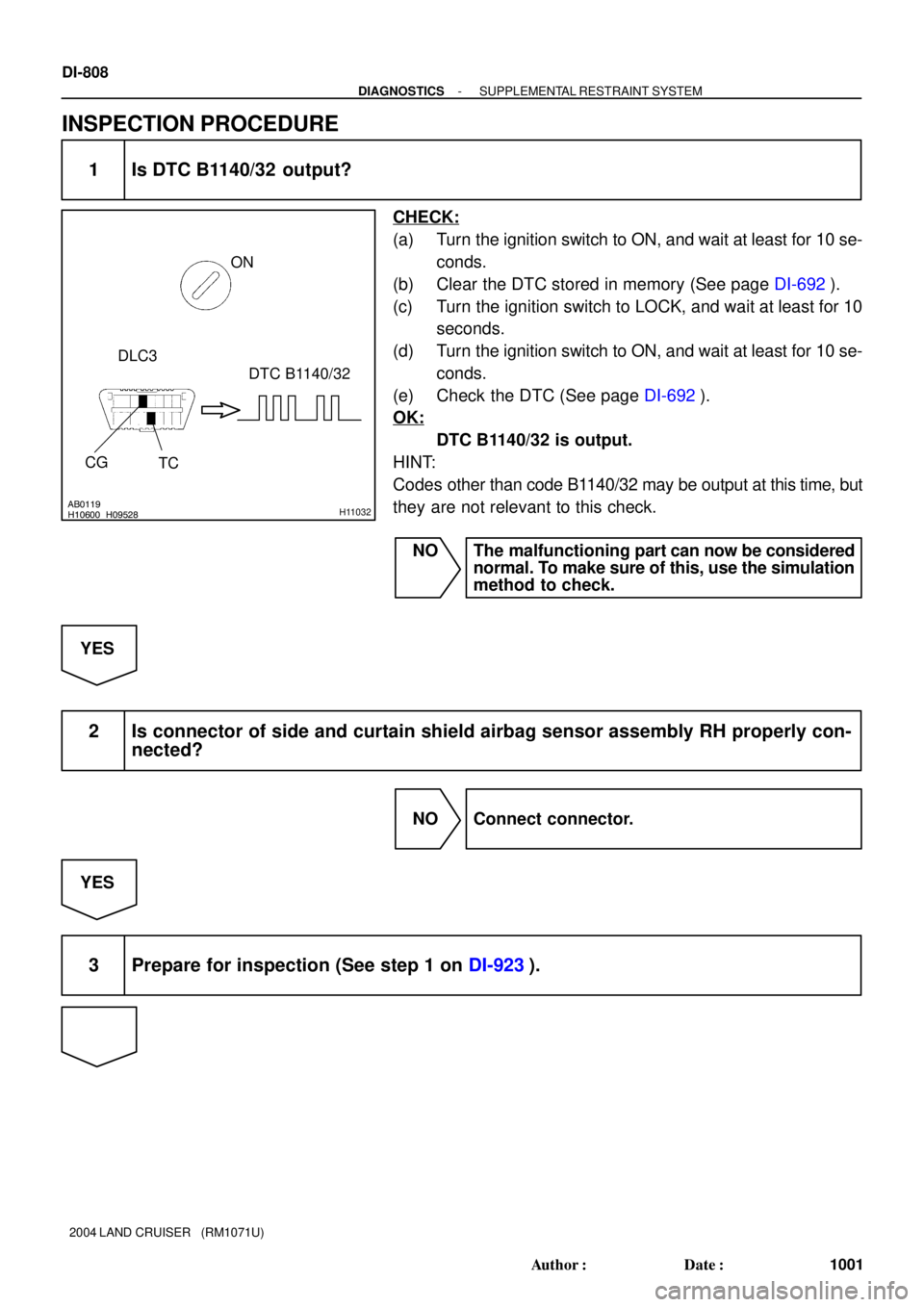
1 Is DTC B1140/32 output?
CHECK:
(a) Turn the ignition switch to ON, and wait at least for 10 se-
conds.
(b) Clear the DTC stored in memory (See page DI-692).
(c) Turn the ignition switch to LOCK, and wait at least for 10
seconds.
(d) Turn the ignition switch to ON, and wait at least for 10 se-
conds.
(e) Check the DTC (See page DI-692).
OK:
DTC B1140/32 is output.
HINT:
Codes other than code B1140/32 may be output at this time, but
they are not relevant to this check.
NO The malfunctioning part can now be considered
normal. To make sure of this, use the simulation
method to check.
YES
2 Is connector of side and curtain shield airbag sensor assembly RH properly con-
nected?
NO Connect connector.
YES
3 Prepare for inspection (See step 1 on DI-923).
Page 1592 of 3115
 (-)
Side and Curtain
Shield Airbag
Sensor Assembly RH
SSR+
VUPRSSR- Floor No. 2 Wire
AB0119
H01013
H16865H17101
Airbag
Sensor
A")
H01013H16864H17100
Airbag
Sensor
Assembly
Airbag Sensor Assembly
(+) (-)
Side and Curtain
Shield Airbag
Sensor Assembly RH
SSR+
VUPRSSR- Floor No. 2 Wire
AB0119
H01013
H16865H17101
Airbag
Sensor
Assembly
Airbag Sensor Assembly
ON
Side and Curtain
Shield Airbag
Sensor Assembly RH
(-) (+) SSR+ESR
SSR-
VUPR
Floor No. 2 Wire
- DIAGNOSTICSSUPPLEMENTAL RESTRAINT SYSTEM
DI-81 1
1004 Author�: Date�:
2004 LAND CRUISER (RM1071U)
6 Check floor No. 2 wire (to ground).
CHECK:
Measure the resistance between the body ground and each of
VUPR, SSR+ and SSR- of the floor No. 2 wire connector on the
airbag sensor assembly side.
OK:
Resistance: 1 MW or Higher
NG Repair or replace floor No. 2 wire.
OK
7 Check floor No. 2 wire (to B+).
PREPARATION:
Connect the negative (-) terminal cable to the battery, and wait
at least for 2 seconds.
CHECK:
(a) Turn the ignition switch to ON.
(b) Measure the voltage between the body ground and each
of VUPR, SSR+, SSR- and ESR of the floor No. 2 wire
connector on the airbag sensor assembly side.
OK:
Voltage: Below 1 V
NG Repair or replace floor No. 2 wire.
OK
Page 1593 of 3115

H01012AB0119H10600H01065H01066H21139
Airbag
Sensor
Assembly
CG
TCON
" u
DTC B1140/32 " u
DLC3 Side and Curtain
Shield Airbag
Sensor Assembly LH
DTC B1141/33
DI-812
- DIAGNOSTICSSUPPLEMENTAL RESTRAINT SYSTEM
1005 Author�: Date�:
2004 LAND CRUISER (RM1071U)
8 Check airbag sensor assembly.
PREPARATION:
(a) Turn the ignition switch to LOCK.
(b) Disconnect the negative (-) terminal cable from the bat-
tery, and wait at least for 90 seconds.
(c) Connect the connector to the airbag sensor assembly.
(d) Change the side and curtain shield airbag sensor assem-
bly LH position with RH position.
(e) Connect the negative (-) terminal cable to the battery,
and wait at least for 2 seconds.
CHECK:
(a) Turn the ignition switch to ON, and wait at least for 10 se-
conds.
(b) Clear the DTC stored in memory (See page DI-692).
(c) Turn the ignition switch to LOCK, and wait at least for 10
seconds.
(d) Turn the ignition switch to ON, and wait at least for 10 se-
conds.
(e) Check the DTC (See page DI-692).
OK:
Neither DTC B1140/32 nor B1141/33 are not output.
HINT:
Codes other than code B1140/32 or B1141/33 may be output
at this time, but they are not relevant to this check.
NG Replace airbag sensor assembly
(DTC B1140/32 is output).
NG Replace side and curtain shield airbag sensor
assembly RH (DTC B1141/33 is output).
OK
From the results of the above inspection, the malfunctioning part can now be considered normal.
To make sure of this, use the simulation method to check.
Page 1595 of 3115
AB0119H09530H10600H11034
ON
CG
TCDTC B1141/33
DLC3
DI-814
- DIAGNOSTICSSUPPLEMENTAL RESTRAINT SYSTEM
1007 Author�: Date�:
2004 LAND CRUISER (RM1071U)
INSPECTION PROCEDURE
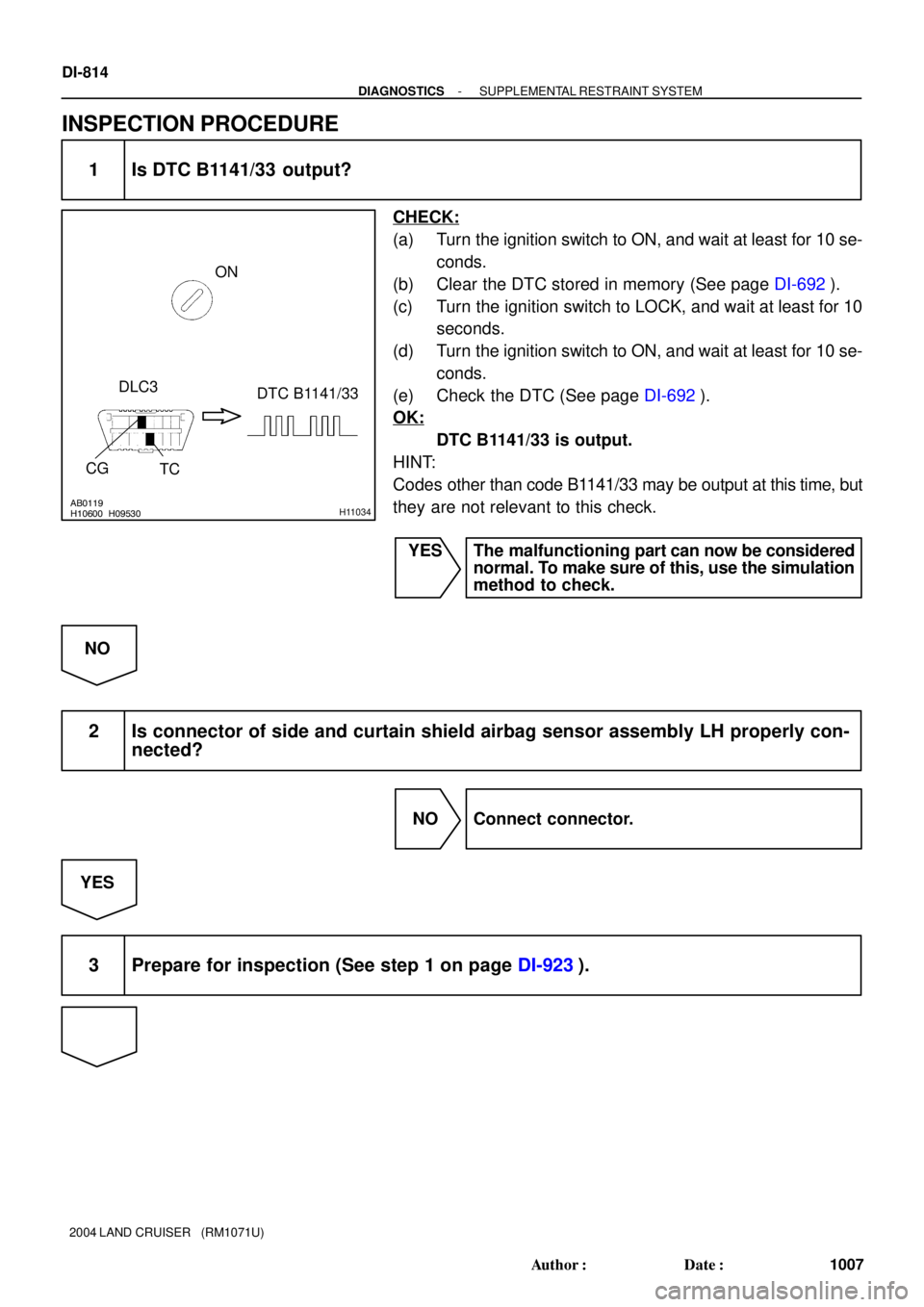
1 Is DTC B1141/33 output?
CHECK:
(a) Turn the ignition switch to ON, and wait at least for 10 se-
conds.
(b) Clear the DTC stored in memory (See page DI-692).
(c) Turn the ignition switch to LOCK, and wait at least for 10
seconds.
(d) Turn the ignition switch to ON, and wait at least for 10 se-
conds.
(e) Check the DTC (See page DI-692).
OK:
DTC B1141/33 is output.
HINT:
Codes other than code B1141/33 may be output at this time, but
they are not relevant to this check.
YES The malfunctioning part can now be considered
normal. To make sure of this, use the simulation
method to check.
NO
2 Is connector of side and curtain shield airbag sensor assembly LH properly con-
nected?
NO Connect connector.
YES
3 Prepare for inspection (See step 1 on page DI-923).
Page 1598 of 3115
 (+)SSL+
SSL-
Side and Curtain Shield
Airbag Sensor Assembly LH
Floor No. 1 Wire
H01008AB0119H16869H17105
Airbag
Sensor
Assem")
H01008H16868H17104
Airbag
Sensor
Assembly
Airbag Sensor Assembly
VUPL
(-) (+)SSL+
SSL-
Side and Curtain Shield
Airbag Sensor Assembly LH
Floor No. 1 Wire
H01008AB0119H16869H17105
Airbag
Sensor
Assembly
Airbag Sensor Assembly
(-) (+) ESL SSL+
VUPLON
Side and Curtain Shield
Airbag Sensor Assembly LH
SSL-Floor No. 1 Wire
- DIAGNOSTICSSUPPLEMENTAL RESTRAINT SYSTEM
DI-817
1010 Author�: Date�:
2004 LAND CRUISER (RM1071U)
6 Check floor No. 1 wire (to ground).
CHECK:
Measure the resistance between the body ground and each of
VUPL, SSL+ and SSL- of the floor No. 1 wire connector on the
airbag sensor assembly side.
OK:
Resistance: 10 kW or Higher
NG Repair or replace floor No. 1 wire.
OK
7 Check floor No. 1 wire (to B+).
PREPARATION:
Connect the negative (-) terminal cable to the battery, and wait
at least for 2 seconds.
CHECK:
(a) Turn the ignition switch to ON.
(b) Measure the voltage between the body ground and each
of VUPL, SSL+, SSL- and ESL of the floor No. 1 wire con-
nector on the airbag sensor assembly side.
OK:
Voltage: Below 1 V
NG Repair or replace floor No. 1 wire.
OK