Page 1478 of 3115

F03702
ON
Up
Down TOYOTA
Hand-held
Tester
F05991
Tilt MotorTilt Motor
Connector
Telescopic Motor
Connector
DI-682- DIAGNOSTICSPOWER TILT AND POWER TELESCOPIC STEERING
COLUMN
875 Author�: Date�:
2004 LAND CRUISER (RM1071U)
INSPECTION PROCEDURE
In case of using TOYOTA hand-held tester, start inspection from step 1.
In case of not using TOYOTA hand-held tester, start inspection from step 2.
1 Check tilt motor operation using TOYOTA hand-held tester.
PREPARATION:
(a) Connect the TOYOTA hand-held tester to the DLC3.
(b) Turn ignition switch ON and push the TOYOTA hand-held
tester main switch ON.
(c) Select the ACTIVE TEST mode on the TOYOTA hand-
held tester.
CHECK:
Check that the steering wheel tilt up (down) and confirm that tilt
position value change when the ACTIVE TEST carried out.
OK:
Steering wheel must be moved upward (downward).
Tilt position value must be changed.
OK Proceed to next circuit inspection shown on the
problem symptoms table (See page DI-663).
NG
2 Check tilt motor.
PREPARATION:
(a) Disconnect tilt motor connector and telescopic motor con-
nector.
(b) Remove tilt motor (See page SR-30).
CHECK:
Connect telescopic motor connector to tilt motor. Then confirm
that tilt motor moved when operating the manual switch.
NG Replace tilt motor.
OK
Page 1480 of 3115

F17326
C17
Tilt & Telescopic Unit (Combination Switch)Tilt & Telescopic ECU
MSW V (1.2 kW)2
5 T7VC 16
8
V-YT7
Telescopic
Short Tilt Down Telescopic
Long Tilt Up (430 W) (200 W) (160 W)
V
V-YII5
II58
9 VC
MSW
BE6653
F03819F04058
Telescopic
Extend
(Long)
TOYOTA
Hand-held
TesterTilt Up ON
Tilt Down Telescopic
Contract
(Short)
- DIAGNOSTICSPOWER TILT AND POWER TELESCOPIC STEERING
COLUMNDI-687
880 Author�: Date�:
2004 LAND CRUISER (RM1071U)
Tilt and Telescopic Manual Switch Circuit
CIRCUIT DESCRIPTION
The different voltage signals which are occurred by operating the manual switch are sent to the tilt and tele-
scopic ECU.
WIRING DIAGRAM
INSPECTION PROCEDURE
1 Check tilt and telescopic manual switch voltage.
When using TOYOTA hand-held tester
PREPARATION:
(a) Connect the TOYOTA hand-held tester to the DLC3.
(b) Turn ignition switch ON and push the TOYOTA hand-held
tester main switch ON.
(c) Select DATALIST mode on the TOYOTA hand-held tes-
ter.
CHECK:
Read the voltages on the tester screen when operating the
manual switch.
DI23O-13
Page 1487 of 3115

F05340
TOYOTA Hand-held Tester
DLC3
DI239-15
N09214
DLC3 DI-658
- DIAGNOSTICSPOWER TILT AND POWER TELESCOPIC STEERING
COLUMN
851 Author�: Date�:
2004 LAND CRUISER (RM1071U)
PRE-CHECK
1. DESCRIPTION
(a) DIAGNOSIS SYSTEM
When troubleshooting Multiplex OBD (M-OBD) vehicles,
the only difference from the usual troubleshooting proce-
dure is that you connect the TOYOTA hand-held tester
to vehicle, and read off various data output from the ve-
hicle's Power Tilt and Telescopic Steering ECU.
The Power Tilt and Telescopic Steering ECU records the
applicable DTCs when the computer detects a malfunc-
tion in the computer itself or its circuit.
To check the DTCs, connect a TOYOTA hand-held tester
to DLC3 on the vehicle. The TOYOTA hand-held tester
enables you to erase the DTCs and activate the several
actuators and check freeze frame data and various forms
on steering data.
(b) DATA LINK CONNECTOR 3 (DLC3)
The Power Tilt and Telescopic Steering ECU uses ISO
14230 for communication. The terminal arrangement of
DLC3 complies with SAE J1962 and matches the ISO
14230 format.
Terminal No.ConnectionVoltage or ResistanceCondition
7Bus + LinePulse generationDuring transmission
4Chassis Grounde Body Ground 1 W or lessAlways
5Signal Grounde Body Ground 1 W or lessAlways
16Battery Positivee Body Ground 9 - 14 VAlways
HINT:
If your display shows ºUNABLE TO CONNECT TO VEHICLEº
when you have connected the cable of TOYOTA hand-held
tester to DLC3, turned the ignition switch ON and operated the
TOYOTA hand-held tester, there is a problem on the vehicle
side or tester side.
�If communication is normal when the tester is connected
to another vehicle, inspect DLC3 on the original vehicle.
�If communication is still not possible when the tester is
connected to another vehicle, the problem is probably in
the tester itself, so consult the Service Department listed
in the tester's Operator's Manual.
Page 1488 of 3115
F05340
TOYOTA Hand-held Tester
DLC3
- DIAGNOSTICSPOWER TILT AND POWER TELESCOPIC STEERING
COLUMNDI-659
852 Author�: Date�:
2004 LAND CRUISER (RM1071U)
2. DIAGNOSIS INSPECTION
(a) Check the DTC.
(1) Prepare the TOYOTA hand-held tester.
(2) Connect the TOYOTA hand-held tester to DLC3 at
the lower of the instrument panel.
(3) Turn the ignition switch ON and turn the TOYOTA
hand-held tester switch ON.
(4) Use the TOYOTA hand-held tester to check the
DTCs and freeze frame data, note or print them
(See the Operator's Manual for operating instruc-
tions.).
(5) See page DI-660 to confirm the details of the DTC.
(b) Clear the DTC.
The following actions will erase the DTC and freeze frame
data.
�When using the TOYOTA hand-held tester:
Operating the TOYOTA hand-held tester to erase
the DTCs (See the Operator's Manual for operating
instructions.).
�When not using the TOYOTA hand-held tester:
Disconnecting the battery terminals.
Page 1490 of 3115
DI-664- DIAGNOSTICSPOWER TILT AND POWER TELESCOPIC STEERING
COLUMN
857 Author�: Date�:
2004 LAND CRUISER (RM1071U)Symptom
Suspect AreaSee page
Both away and return:
Only auto away/return function does not operate
1. Check status of auto away function using TOYOTA
hand-held tester
2. Multiplex communication system
3. Ignition switch
4. Key unlock warning switch
5. Tilt motor circuit
6. Telescopic motor circuit
7. Tilt and telescopic ECU
-
-
BE-29
BE-29
DI-681
DI-684
IN-36
Only away:
Only Auto away/return function does not operate
1. Multiplex communication system
2. Key unlock warning switch
3. Ignition switch
4. Tilt motor circuit
5. Telescopic motor circuit
6. Tilt and telescopic ECU-
BE-29
BE-29
DI-681
DI-684
IN-36
Only return:
Only auto away/return function does not operate
1. Multiplex communication system
2. Key unlock warning switch
3. Ignition switch
4. Tilt motor circuit
5. Telescopic motor circuit
6. Tilt and telescopic ECU-
BE-29
BE-29
DI-681
DI-684
IN-36
Page 1494 of 3115
AB0119H02243H10600
H21263
H10679
D Squib
Airbag
Sensor
Assembly
CG
TCON
DTC B0100/13
DLC3
Spiral
Cable
" u
- DIAGNOSTICSSUPPLEMENTAL RESTRAINT SYSTEM
DI-713
906 Author�: Date�:
2004 LAND CRUISER (RM1071U)
4 Check airbag sensor assembly.
PREPARATION:
(a) Connect the connector to the airbag sensor assembly.
(b) Connect the negative (-) terminal cable to the battery,
and wait at least for 2 seconds.
CHECK:
(a) Turn the ignition switch to ON, and wait at least for 10 se-
conds.
(b) Clear the DTC stored in memory (See page DI-692).
(c) Turn the ignition switch to LOCK, and wait at least for 10
seconds.
(d) Turn the ignition switch to ON, and wait at least for 10 se-
conds.
(e) Check the DTC (See page DI-692).
OK:
DTC B0100/13 is not output.
HINT:
Codes other than code B0100/13 may be output at this time, but
they are not relevant to this check.
NG Replace airbag sensor assembly.
OK
Page 1495 of 3115

AB0119FI1390H10600
H21267
H20680
D Squib
Airbag
Sensor
Assembly
CG
TCON
DTC B0100/13
DLC3
" uSpiral
Cable
DI-714
- DIAGNOSTICSSUPPLEMENTAL RESTRAINT SYSTEM
907 Author�: Date�:
2004 LAND CRUISER (RM1071U)
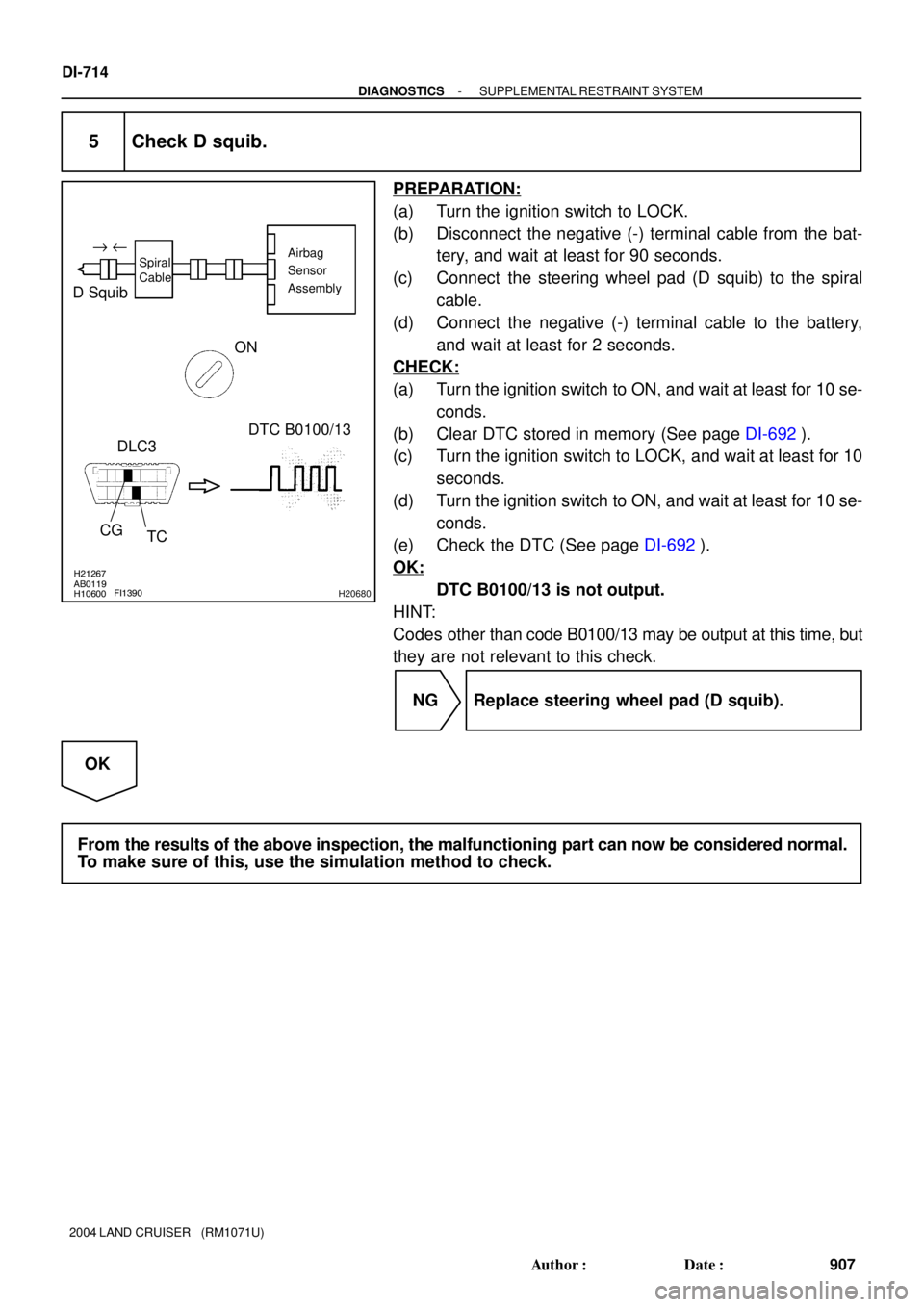
5 Check D squib.
PREPARATION:
(a) Turn the ignition switch to LOCK.
(b) Disconnect the negative (-) terminal cable from the bat-
tery, and wait at least for 90 seconds.
(c) Connect the steering wheel pad (D squib) to the spiral
cable.
(d) Connect the negative (-) terminal cable to the battery,
and wait at least for 2 seconds.
CHECK:
(a) Turn the ignition switch to ON, and wait at least for 10 se-
conds.
(b) Clear DTC stored in memory (See page DI-692).
(c) Turn the ignition switch to LOCK, and wait at least for 10
seconds.
(d) Turn the ignition switch to ON, and wait at least for 10 se-
conds.
(e) Check the DTC (See page DI-692).
OK:
DTC B0100/13 is not output.
HINT:
Codes other than code B0100/13 may be output at this time, but
they are not relevant to this check.
NG Replace steering wheel pad (D squib).
OK
From the results of the above inspection, the malfunctioning part can now be considered normal.
To make sure of this, use the simulation method to check.
Page 1499 of 3115

AB0119W02044H19230H10600
H21272
H10685
D Squib
TCON
DTC B0101/14
DLC3"u
D+D-
CG
Spiral
CableAirbag
Sensor
Assembly
DI-718
- DIAGNOSTICSSUPPLEMENTAL RESTRAINT SYSTEM
911 Author�: Date�:
2004 LAND CRUISER (RM1071U)
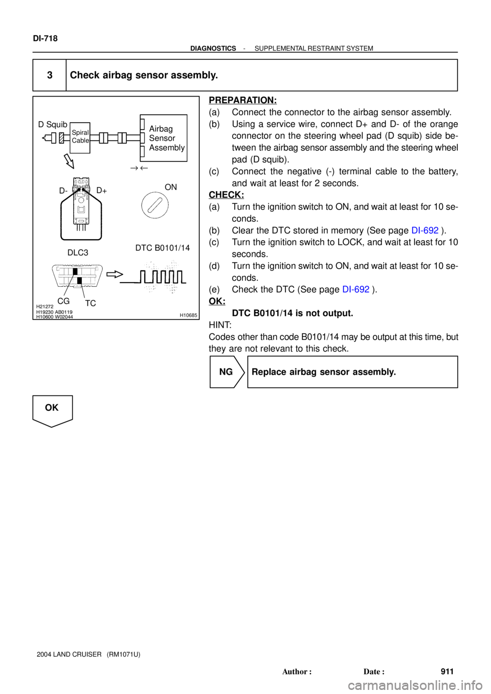
3 Check airbag sensor assembly.
PREPARATION:
(a) Connect the connector to the airbag sensor assembly.
(b) Using a service wire, connect D+ and D- of the orange
connector on the steering wheel pad (D squib) side be-
tween the airbag sensor assembly and the steering wheel
pad (D squib).
(c) Connect the negative (-) terminal cable to the battery,
and wait at least for 2 seconds.
CHECK:
(a) Turn the ignition switch to ON, and wait at least for 10 se-
conds.
(b) Clear the DTC stored in memory (See page DI-692).
(c) Turn the ignition switch to LOCK, and wait at least for 10
seconds.
(d) Turn the ignition switch to ON, and wait at least for 10 se-
conds.
(e) Check the DTC (See page DI-692).
OK:
DTC B0101/14 is not output.
HINT:
Codes other than code B0101/14 may be output at this time, but
they are not relevant to this check.
NG Replace airbag sensor assembly.
OK