Page 1893 of 3115
A04451
Turn
A04452
Tension
Turn
A04453
Turn
P20636
1.27 mm
Hexagon
Wrench
A04454
1.27 mm
Hexagon
Wrench
EM-24
- ENGINE MECHANICALTIMING BELT
1597 Author�: Date�:
2004 LAND CRUISER (RM1071U)
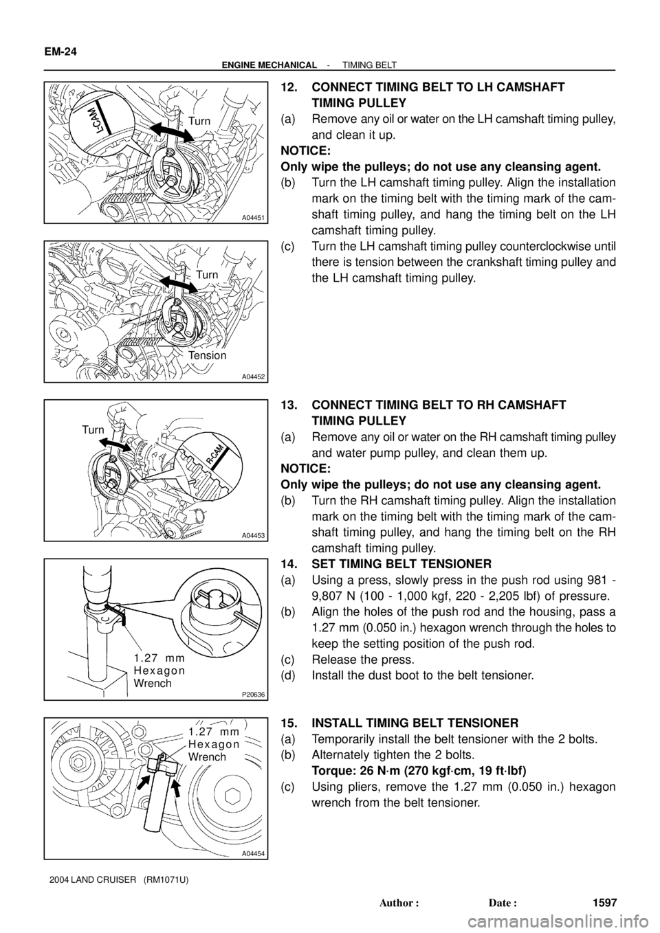
12. CONNECT TIMING BELT TO LH CAMSHAFT
TIMING PULLEY
(a) Remove any oil or water on the LH camshaft timing pulley,
and clean it up.
NOTICE:
Only wipe the pulleys; do not use any cleansing agent.
(b) Turn the LH camshaft timing pulley. Align the installation
mark on the timing belt with the timing mark of the cam-
shaft timing pulley, and hang the timing belt on the LH
camshaft timing pulley.
(c) Turn the LH camshaft timing pulley counterclockwise until
there is tension between the crankshaft timing pulley and
the LH camshaft timing pulley.
13. CONNECT TIMING BELT TO RH CAMSHAFT
TIMING PULLEY
(a) Remove any oil or water on the RH camshaft timing pulley
and water pump pulley, and clean them up.
NOTICE:
Only wipe the pulleys; do not use any cleansing agent.
(b) Turn the RH camshaft timing pulley. Align the installation
mark on the timing belt with the timing mark of the cam-
shaft timing pulley, and hang the timing belt on the RH
camshaft timing pulley.
14. SET TIMING BELT TENSIONER
(a) Using a press, slowly press in the push rod using 981 -
9,807 N (100 - 1,000 kgf, 220 - 2,205 lbf) of pressure.
(b) Align the holes of the push rod and the housing, pass a
1.27 mm (0.050 in.) hexagon wrench through the holes to
keep the setting position of the push rod.
(c) Release the press.
(d) Install the dust boot to the belt tensioner.
15. INSTALL TIMING BELT TENSIONER
(a) Temporarily install the belt tensioner with the 2 bolts.
(b) Alternately tighten the 2 bolts.
Torque: 26 N´m (270 kgf´cm, 19 ft´lbf)
(c) Using pliers, remove the 1.27 mm (0.050 in.) hexagon
wrench from the belt tensioner.
Page 2455 of 3115
LU08P-07
B04470
B04791
RH No.3 Timing Belt Cover
LH No.3 Timing Belt CoverNo.2 Timing Belt Cover
Camshaft Position
Sensor Connector
Engine Wire
Drive Belt Idler PulleyTiming Belt
Fan Bracket
N´m (kgf´cm, ft´lbf) : Specified torqueOil Cooler Pipe
Timing Belt Tensioner Dust Boot
Cover Plate
39 (400,29)
245 (2,500, 181)
32 (330, 24)
16 (160, 12)
7.5 (80, 66 in.´lbf)
16 (160, 12)
Water Bypass
Hose
LU-4
- LUBRICATIONOIL PUMP
1785 Author�: Date�:
2004 LAND CRUISER (RM1071U)
OIL PUMP
COMPONENTS
Page 2464 of 3115
B04486
Push New O-Ring
LU-18
- LUBRICATIONOIL PUMP
1799 Author�: Date�:
2004 LAND CRUISER (RM1071U)
�Parts must be assembled within 5 minutes of ap-
plication. Otherwise the material must be removed
and reapplied.
�Immediately remove nozzle from the tube and rein-
stall cap.
(c) Install the No.2 oil pan with the 20 bolts and 2 nuts. Uni-
formly tighten the bolts and nuts in several passes.
Torque: 7.5 N´m (80 kgf´cm, 66 in.´lbf)
HINT:
Use bolts 14 mm (0.55 in.) in length.
6. INSTALL CRANKSHAFT POSITION SENSOR
(See page IG-13)
7. INSTALL OIL FILTER, OIL COOLER AND FILTER
BRACKET ASSEMBLY
(a) Install the a new gasket to the oil filter bracket.
(b) Install the oil filter, oil cooler and filter bracket assembly
with the 2 bolts and nut.
Torque: 18 N´m (185 kgf´cm, 13 ft´lbf)
(c) Connect the oil pressure switch connector.
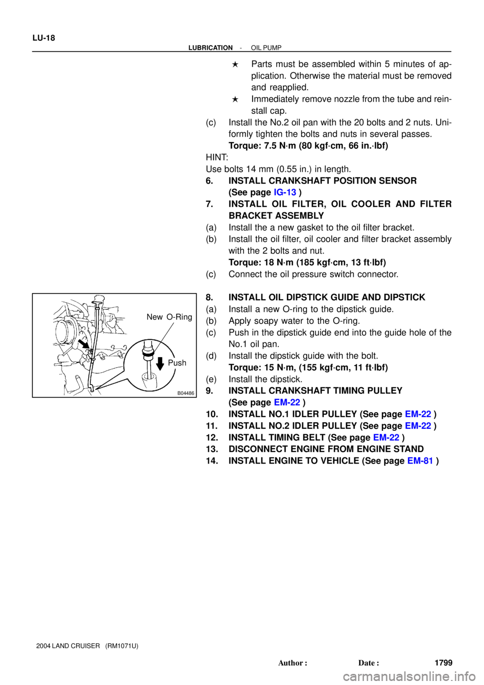
8. INSTALL OIL DIPSTICK GUIDE AND DIPSTICK
(a) Install a new O-ring to the dipstick guide.
(b) Apply soapy water to the O-ring.
(c) Push in the dipstick guide end into the guide hole of the
No.1 oil pan.
(d) Install the dipstick guide with the bolt.
Torque: 15 N´m, (155 kgf´cm, 11 ft´lbf)
(e) Install the dipstick.
9. INSTALL CRANKSHAFT TIMING PULLEY
(See page EM-22)
10. INSTALL NO.1 IDLER PULLEY (See page EM-22)
11. INSTALL NO.2 IDLER PULLEY (See page EM-22)
12. INSTALL TIMING BELT (See page EM-22)
13. DISCONNECT ENGINE FROM ENGINE STAND
14. INSTALL ENGINE TO VEHICLE (See page EM-81)
Page 2509 of 3115
PP1AS-01
PP-14
- PREPARATIONCOOLING
73 Author�: Date�:
2004 LAND CRUISER (RM1071U)
SSM (Special Service Materials)
08826-00100Seal Packing 1282B,
THREE BOND 1282B or equivalent
(FIPG)Water pump
Water inlet housing
Page 2588 of 3115
SS0OA-01
SS-14
- SERVICE SPECIFICATIONSCOOLING
154 Author�: Date�:
2004 LAND CRUISER (RM1071U)
TORQUE SPECIFICATION
Part tightenedN´mkgf´cmft´lbf
Drain plug x Union on cylinder block12.71309
Water pump x Cylinder block Bolt
Stud bolt and nut21
18215
18515
13
Water inlet housing x Water pump1818513
Water inlet x Water inlet housing1919514
Radiator x Fan shroud5.05044 in.´lbf
Radiator x Radiator side support12.71309
Radiator side support x Bracket2020015
Radiator mounting bolt1818513
Radiator mounting nut2020015
Page 2594 of 3115
SS0OR-1 1
SS-8
- SERVICE SPECIFICATIONSENGINE MECHANICAL
148 Author�: Date�:
2004 LAND CRUISER (RM1071U)
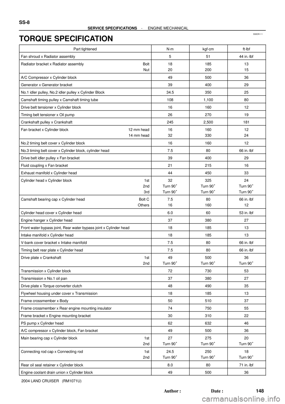
TORQUE SPECIFICATION
Part tightenedN´mkgf´cmft´lbf
Fan shroud x Radiator assembly55144 in.´lbf
Radiator bracket x Radiator assembly Bolt
Nut18
20185
20013
15
A/C Compressor x Cylinder block4950036
Generator x Generator bracket3940029
No.1 idler pulley, No.2 idler pulley x Cylinder Block34.535025
Camshaft timing pulley x Camshaft timing tube1081,10080
Drive belt tensioner x Cylinder block1616012
Timing belt tensioner x Oil pump2627019
Crankshaft pulley x Crankshaft2452,500181
Fan bracket x Cylinder block 12 mm head
14 mm head16
32160
33012
24
No.2 timing belt cover x Cylinder block1616012
No.3 timing belt cover x Cylinder block, cylinder head7.58066 in.´lbf
Drive belt idler pulley x Fan bracket3940029
Fluid coupling x Fan bracket2121516
Exhaust manifold x Cylinder head4445033
Cylinder head x Cylinder block 1st
2nd
3rd32
Turn 90°
Turn 90°325
Turn 90°
Turn 90°24
Turn 90°
Turn 90°
Camshaft bearing cap x Cylinder head Bolt C
Others7.5
1680
16066 in.´lbf
12
Cylinder head cover x Cylinder head6.06053 in.´lbf
Engine hanger x Cylinder head3738027
Front water bypass joint, Rear water bypass joint x Cylinder head1818513
Intake manifold x Cylinder head1818513
V-bank cover bracket x Intake manifold7.58066 in.´lbf
Timing belt rear plate x Cylinder head7.58066 in.´lbf
Drive plate x Crankshaft 1st
2nd49
Turn 90°500
Turn 90°36
Turn 90°
Transmission x Cylinder block7273053
Transmission x No.1 oil pan3738027
Drive plate x Torque converter clutch4849035
Flywheel housing under cover x Transmission1818513
Frame crossmember x Body5051037
Frame crossmember x Rear engine mounting insulator7475055
Frame bracket x Engine mounting bracket3031022
PS pump x Cylinder head6263246
A/C compressor x Cylinder block, Fan bracket4950036
Main bearing cap x Cylinder block 1st
2nd27
Turn 90°275
Turn 90°20
Turn 90°
Connecting rod cap x Connecting rod 1st
2nd24.5
Turn 90°250
Turn 90°18
Turn 90°
Rear oil seal retainer x Cylinder block8.08071 in.´lbf
Engine coolant drain union x Cylinder block4950036
Page 2614 of 3115
SS0CC-19
SS-12
- SERVICE SPECIFICATIONSSFI
152 Author�: Date�:
2004 LAND CRUISER (RM1071U)
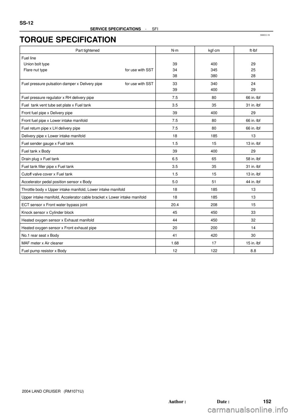
TORQUE SPECIFICATION
Part tightenedN´mkgf´cmft´lbf
Fuel line
Union bolt type
Flare nut type for use with SST
39
34
38400
345
38029
25
28
Fuel pressure pulsation damper x Delivery pipe for use with SST33
39340
40024
29
Fuel pressure regulator x RH delivery pipe7.58066 in.´lbf
Fuel tank vent tube set plate x Fuel tank3.53531 in.´lbf
Front fuel pipe x Delivery pipe3940029
Front fuel pipe x Lower intake manifold7.58066 in.´lbf
Fuel return pipe x LH delivery pipe7.58066 in.´lbf
Delivery pipe x Lower intake manifold1818513
Fuel sender gauge x Fuel tank1.51513 in.´lbf
Fuel tank x Body3940029
Drain plug x Fuel tank6.56558 in.´lbf
Fuel tank filler pipe x Fuel tank3.53531 in.´lbf
Cutoff valve cover x Fuel tank1.51513 in.´lbf
Accelerator pedal position sensor x Body5.05144 in.´lbf
Throttle body x Upper intake manifold, Lower intake manifold1818513
Upper intake manifold, Accelerator cable bracket x Lower intake manifold1818513
ECT sensor x Front water bypass joint20.420815
Knock sensor x Cylinder block4545033
Heated oxygen sensor x Exhaust manifold4445032
Heated oxygen sensor x Front exhaust pipe2020014
No.1 rear seat x Body4142030
MAF meter x Air cleaner1.681715 in.´lbf
Fuel pump resistor x Body121228.8
Page 2670 of 3115
FI2553
SST
B04902Fuel Pump Connector
Disconnect SF-2
- SFISFI SYSTEM
1701 Author�: Date�:
2004 LAND CRUISER (RM1071U)
(c) Do not a severe impact during removal or installation.
Handle all SFI parts carefully, especially the ECM.
(d) Be careful during the troubleshooting as there are numer-
ous transistor circuit, and even slight terminal contact can
cause further troubles.
(e) Do not open the ECM cover.
(f) When inspecting in rainy weather, take care to prevent
entry of water. Also, when washing the engine compart-
ment, prevent water from getting on the SFI parts and the
wiring connectors.
(g) Parts should be replaced as the original assembly.
(h) Care should be taken when pulling out and inserting the
wiring connectors.
(1) Release the lock and pull out the connector.
(2) Fully insert the connector and check that it is locked.
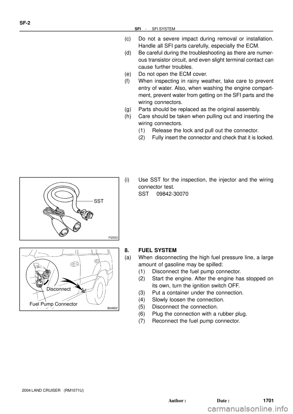
(i) Use SST for the inspection, the injector and the wiring
connector test.
SST 09842-30070
8. FUEL SYSTEM
(a) When disconnecting the high fuel pressure line, a large
amount of gasoline may be spilled:
(1) Disconnect the fuel pump connector.
(2) Start the engine. After the engine has stopped on
its own, turn the ignition switch OFF.
(3) Put a container under the connection.
(4) Slowly loosen the connection.
(5) Disconnect the connection.
(6) Plug the connection with a rubber plug.
(7) Reconnect the fuel pump connector.
Page:
< prev 1-8 9-16 17-24