Page 1090 of 3115
DI-350
- DIAGNOSTICSENGINE
543 Author�: Date�:
2004 LAND CRUISER (RM1071U)
Fuel Pump Control Circuit
CIRCUIT DESCRIPTION
Refer to DTC P0230 on page DI-162.
WIRING DIAGRAM
Refer to DTC P0230 on page DI-162.
INSPECTION PROCEDURE
Hand-held tester:
1 Check fuel pump operation (See page SF-7).
OK Go to step 8.
NG
2 Connect hand-held tester, and check operation of fuel pump relay.
PREPARATION:
(a) Connect the hand-held tester to the DLC3.
(b) Turn the ignition switch ON and push the hand-held tester main switch ON.
(c) Enter the following menus: DIAGNOSIS / ENHANCED OBD II / ACTIVE TEST / FUEL PUMP / SPD.
CHECK:
Check the operation of the fuel pump relay when it is switched ON and OFF by the hand-held tester.
OK:
Operating noise can be heard from the relay.
OK Go to step 4.
NG
3 Check operation of fuel pump relay (See page SF-40).
NG Replace fuel pump relay.
OK
DIB2Y-02
Page 1092 of 3115
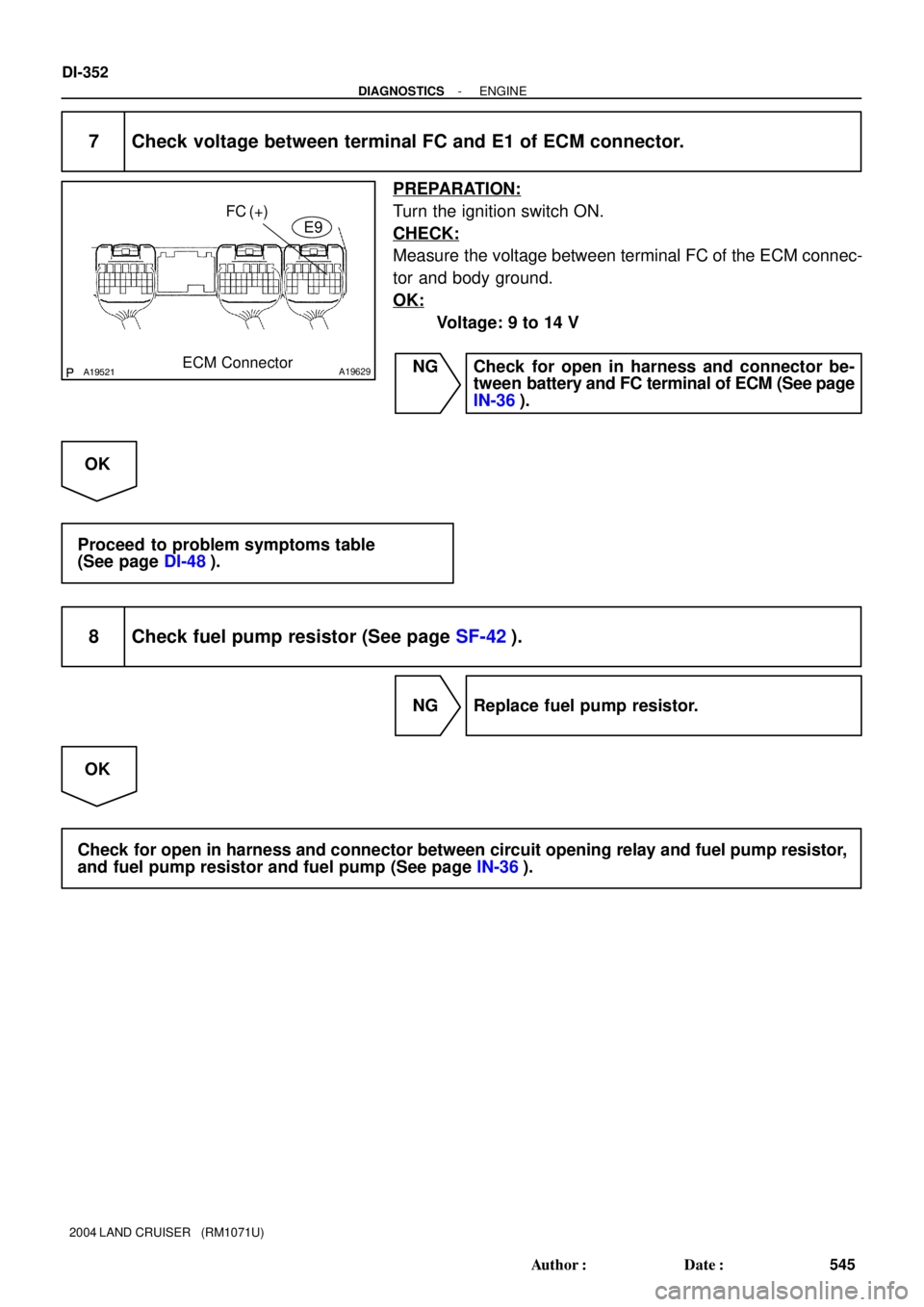
A19521A19629
FC(+)
ECM ConnectorE9
DI-352
- DIAGNOSTICSENGINE
545 Author�: Date�:
2004 LAND CRUISER (RM1071U)
7 Check voltage between terminal FC and E1 of ECM connector.
PREPARATION:
Turn the ignition switch ON.
CHECK:
Measure the voltage between terminal FC of the ECM connec-
tor and body ground.
OK:
Voltage: 9 to 14 V
NG Check for open in harness and connector be-
tween battery and FC terminal of ECM (See page
IN-36).
OK
Proceed to problem symptoms table
(See page DI-48).
8 Check fuel pump resistor (See page SF-42).
NG Replace fuel pump resistor.
OK
Check for open in harness and connector between circuit opening relay and fuel pump resistor,
and fuel pump resistor and fuel pump (See page IN-36).
Page 1094 of 3115
A19521A19629
FC(+)
ECM ConnectorE9
DI-354
- DIAGNOSTICSENGINE
547 Author�: Date�:
2004 LAND CRUISER (RM1071U)
6 Check voltage between terminal FC of ECM connector and body ground.
PREPARATION:
Turn the ignition switch ON.
CHECK:
Measure the voltage between terminal FC of the ECM connec-
tor and body ground.
OK:
Voltage: 9 to 14 V
NG Check for open in harness and connector be-
tween battery and FC terminal of ECM (See page
IN-36).
OK
Proceed to problem symptoms table
(See page DI-48).
7 Check fuel pump resistor (See page SF-42).
NG Replace fuel pump resistor.
OK
Check for open in harness and connector between circuit opening relay and fuel pump resistor,
fuel pump resistor and fuel pump (See page IN-36).
Page 1095 of 3115
A21366
Engine
Room
R/B11ECM
W
E9 11
C13
C12
SB10
Battery7
4I18
Ignition
Switch
73E
3Q 6
B-R
MET
Combination
Meter
Malfunction
Indicator
Lamp AM2IG2 AM2
W
B-RSB
2Q 2D32 78
Cowl Side
J/B RHA
AJ4
J/B W-R
2E 41
10
2A
W-R
1B 9
1C 1
F15 2
Fusible Link
Block B-G
120A MAIN
- DIAGNOSTICSENGINE
DI-355
548 Author�: Date�:
2004 LAND CRUISER (RM1071U)
MIL Circuit
CIRCUIT DESCRIPTION
If the ECM detects a trouble, the MIL lights up. At this time, the ECM records a DTC in the memory.
WIRING DIAGRAM
DIC2V-01
Page 1096 of 3115

INSPECTION PROCEDURE
HINT:
Troubleshoot each trouble symptom in accordance with the chart below .")
A21033ECM ConnectorW
E9
DI-356
- DIAGNOSTICSENGINE
549 Author�: Date�:
2004 LAND CRUISER (RM1071U)
INSPECTION PROCEDURE
HINT:
Troubleshoot each trouble symptom in accordance with the chart below .
MIL remains onStart inspection from step 1
MIL does not light upStart inspection from step 3
1 Clear DTC.
(a) Connect the hand-held tester or the OBD II scan tool to the DLC3.
(b) Turn the ignition switch ON and push the hand-held tester or the OBD II scan tool main switch ON.
(c) Read the DTC (See page DI-3).
(d) Clear the DTC (See page DI-3).
(e) Check that MIL does not light up.
Standard: MIL does not light up
OK Repair circuit indicated by output code
(See page DI-36).
NG
2 Check harness and connector (Check for short in wire harness).
(a) Disconnect the E9 ECM connector.
(b) Turn the ignition switch ON.
(c) Check that MIL does not light up.
Standard: MIL does not light up
OK Replace ECM (See page SF-60).
NG
Check and repair harness and connector be-
tween combination meter and ECM (See page
IN-36).
Page 1097 of 3115
- DIAGNOSTICSENGINE
DI-357
550 Author�: Date�:
2004 LAND CRUISER (RM1071U)
3 Check that MIL lights up.
Check that MIL lights up when turning the ignition switch ON.
Standard: MIL lights up
OK System OK.
NG
4 Inspect combination meter assy (MIL circuit).
See the combination meter troubleshooting on page BE-63.
NG Repair or replace bulb or combination meter as-
sembly.
OK
Check and repair harness and connector be-
tween combination meter and ECM (See page
IN-36).
Page 1105 of 3115

A21543
1
23
4 EFI or ECD Relay
A19522A19630
HT1A HT1BE6
ECM Connector HT2A
HT2B
DI-56
- DIAGNOSTICSENGINE
249 Author�: Date�:
2 Check EFI or ECD relay.
PREPARATION:
Remove the EFI or ECD relay from the engine room R/B.
CHECK:
Inspect the EFI or ECD relay.
OK:
Terminal No.ConditionSpecified Condition
2 - 4ConstantContinuity
UsuallyNo Continuity
1 - 3Apply B+ between
terminals 2 and 4Continuity
NG Replace EFI or ECD relay.
OK
3 Check voltage between terminals HT1A, HT2A, HT1B, HT2B of ECM connectors
and body ground.
PREPARATION:
Turn the ignition switch ON.
CHECK:
Measure the voltage between terminals of the ECM connectors
and body ground.
HINT:
�Connect terminal HT1A to the bank 1 sensor 1.
�Connect terminal HT1B to the bank 1 sensor 2.
�Connect terminal HT2A to the bank 2 sensor 1.
�Connect terminal HT2B to the bank 2 sensor 2.
OK:
Tester ConnectionSpecified Condition
HT1A (E6-4) - Body ground9 to 14 V
HT1B (E6-5) - Body ground9 to 14 V
HT2A (E6-33) - Body ground9 to 14 V
HT2B (E6-25) - Body ground9 to 14 V
OK Replace ECM (See page SF-60).
NG
Check and repair harness or connector between EFI or ECD relay and heated oxygen sensor, and
heated oxygen sensor and ECM (See page IN-36).
Page 1109 of 3115

INSPECTION PROCEDURE
HINT:
Read freeze frame data using the hand-held tester or the OBD II scan tool. Freeze frame data reco")
DI-60
- DIAGNOSTICSENGINE
253 Author�: Date�:
2004 LAND CRUISER (RM1071U)
INSPECTION PROCEDURE
HINT:
Read freeze frame data using the hand-held tester or the OBD II scan tool. Freeze frame data records the
engine conditions when a malfunction is detected. When troubleshooting, freeze frame data can help deter-
mine if the vehicle was running or stopped, if the engine was warmed up or not, if the air-fuel ratio was lean
or rich, and other data from the time the malfunction occurred.
1 Connect OBD II scan tool or hand-held tester, and read value of mass air flow
rate.
PREPARATION:
(a) Connect the OBD II scan tool or hand-held tester to the DLC3.
(b) Turn the ignition switch ON and push the OBD II scan tool or the hand-held tester main switch ON.
(c) Start the engine.
(d) When using hand-held tester, enter the following menus: DIAGNOSIS / ENHANCED OBD II / DATA
LIST / ALL / MAF.
CHECK:
Read the mass air flow rate on the OBD II scan tool or the hand-held tester.
RESULT:
Air Flow Rate (gm/s)Proceed to
0.0A
271.0 or moreB
Between 1 and 270.0 (*1)C
*1: The value must be changed when the throttle valve is opened or closed.
B Go to step 6.
C Check for intermittent problems
(See page DI-3).
A