Page 5 of 2389

7. When necessary, use a sealer on gaskets to prevent
leaks.
8. Carefully observe all specifications for bolt tighten-
ing torques. Always use a torque wrench.
9. Use of special service tools (SST) and special ser-
vice materials (SSM) may be required, depending on
the nature of the repair. Be sure to use SST and SSM
where specified and follow the proper work proce-
dure. A list of SST and SSM can be found at the back
of this manual.
10. When replacing fuses, be sure the new fuse has the
correct amperage rating. DO NOT exceed the fuse
amp rating or use one of a lower rating.
11. Care must be taken when jacking up and supporting
the vehicle. Be sure to lift and support the vehicle at
the proper locations.
(a) If the vehicle is to be jacked up only at the front or
rear end, be sure to block the wheels in order to
ensure safety.
(b) After the vehicle is jacked up, be sure to support it
on stands. It is extremely dangerous to do any
work on the vehicle raised on jack alone, even for a
small job that can be finished quickly.
- INTRODUCTIONGeneral Repair InstructionsIN-5
Page 757 of 2389
Fuses
1. GAUGE
2. ±
3. STOP
4. TAIL
5. CIG
6. RADIO
7. TURN
8. DEF±I/UP
9. ±
10. ENGINE
11. WIPER
12. ECU±IG
13. ±
14. IGN
15. ECU±B FUSE AND RELAY BLOCK No±1 (LOCATION: Driver's Side Kick Panel)7.5A
20A
15A
15A
7.5A
7.5A
10A
10A
20A
15A
7.5A
1 0A
FUSE AND RELAY BLOCKS
± BODY ELECTRICAL SYSTEMLocation of Switches and RelaysBE±11
Page 758 of 2389
Fuses
1. HEAD±HI (RH) 15A (CANADA)
2. HEAD±HI (LH) 15A (CANADA)
3. DOME 20A
4. ± ±
5. HEAD (RH) 15A (USA)
HEAD±LO (RH) 15A (CANADA)
6. CHARGE 7.5A
7. ER 15A
8. HAZ.HORN 15A
9. HEAD (LH) 15A (USA)
HEAD±LO (H) 15A (CANADA)Relays
A. A/C FAN No.3 Relay
B. A/C MAGNET CLUTCH Relay
(USA)
DIMMER Relay (CANADA)
C. A/C FAN No.2 Relay
D. FAN No. 1 Relay
E. HEADLIGHT Relay
F. EFI MAIN Relay
G. ENGINE MAIN Relay FUSE AND RELAY BLOCK No±2 (LOCATION: Engine Compartment)
FUSE AND RELAY BLOCKS (Cont'd)
± BODY ELECTRICAL SYSTEMLocation of Switches and RelaysBE±12
Page 958 of 2389

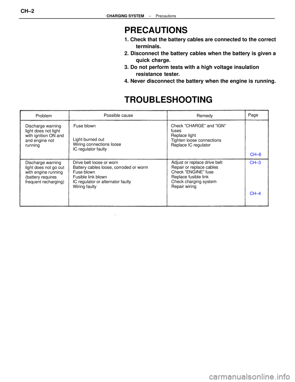
PRECAUTIONS
1. Check that the battery cables are connected to the correct
terminals.
2. Disconnect the battery cables when the battery is given a
quick charge.
3. Do not perform tests with a high voltage insulation
resistance tester.
4. Never disconnect the battery when the engine is running.
TROUBLESHOOTING
Drive belt loose or worn
Battery cables loose, corroded or worm
Fuse blown
Fusible link blown
IC regulator or alternator faulty
Wiring faultyAdjust or replace drive belt
Repair or replace cables
Check ºENGINEº fuse
Replace fusible link
Check charging system
Repair wiring Check ºCHARGEº and ºIGNº
fuses
Replace light
Tighten loose connections
Replace IC regulator
Discharge warning
light does not go out
with engine running
(battery requires
frequent recharging) Discharge warning
light does not light
with ignition ON and
and engine not
runningLight burned out
Wiring connections loose
IC regulator faultyPossible cause
Fuse blownRemedy
Problem
CH±6
CH±4 CH±3 Page
± CHARGING SYSTEMPrecautionsCH±2
Page 959 of 2389

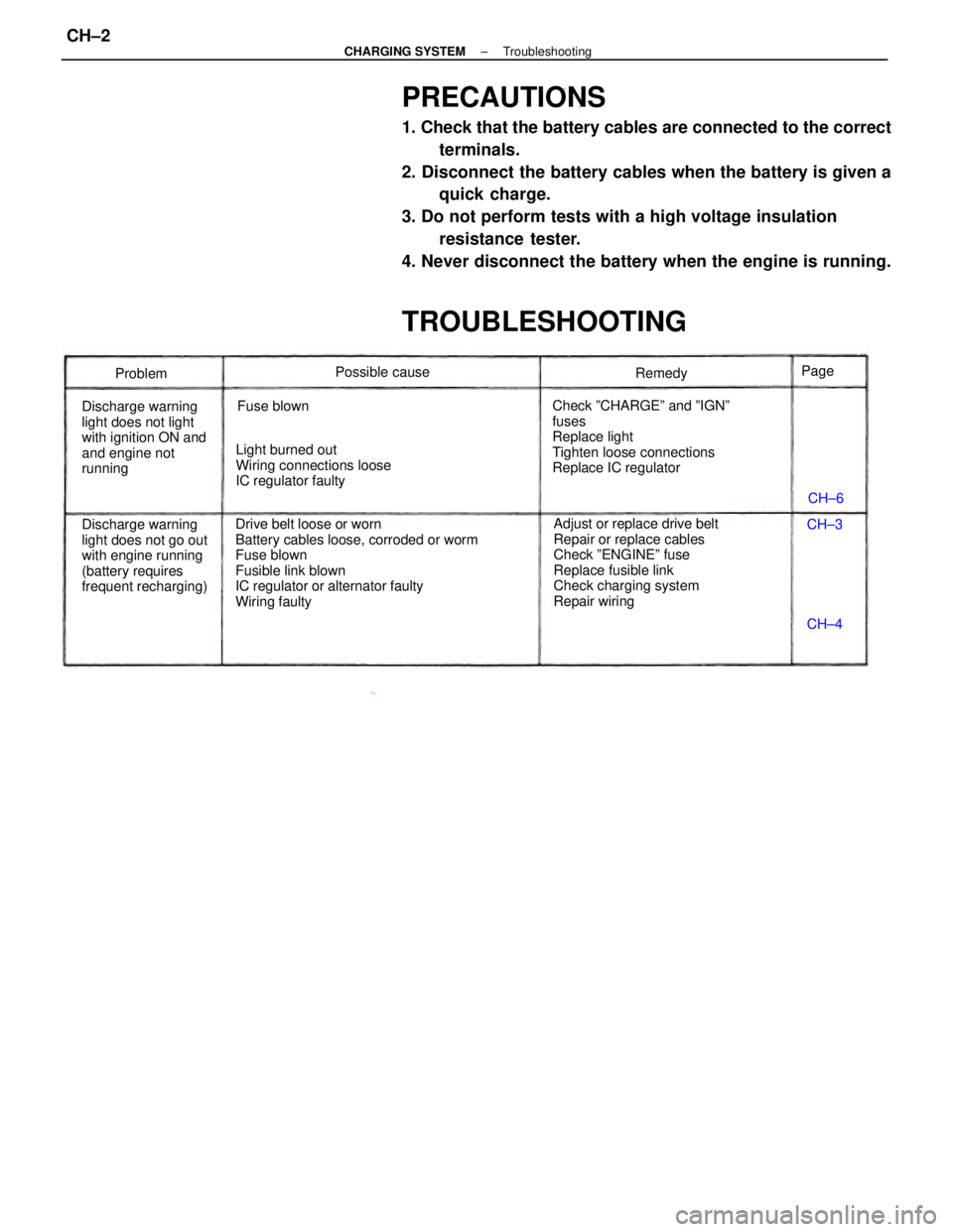
PRECAUTIONS
1. Check that the battery cables are connected to the correct
terminals.
2. Disconnect the battery cables when the battery is given a
quick charge.
3. Do not perform tests with a high voltage insulation
resistance tester.
4. Never disconnect the battery when the engine is running.
TROUBLESHOOTING
Drive belt loose or worn
Battery cables loose, corroded or worm
Fuse blown
Fusible link blown
IC regulator or alternator faulty
Wiring faultyAdjust or replace drive belt
Repair or replace cables
Check ºENGINEº fuse
Replace fusible link
Check charging system
Repair wiring Check ºCHARGEº and ºIGNº
fuses
Replace light
Tighten loose connections
Replace IC regulator
Discharge warning
light does not go out
with engine running
(battery requires
frequent recharging) Discharge warning
light does not light
with ignition ON and
and engine not
runningLight burned out
Wiring connections loose
IC regulator faultyPossible cause
Fuse blownRemedy
Problem
CH±6
CH±4 CH±3 Page
± CHARGING SYSTEMTroubleshootingCH±2
Page 960 of 2389

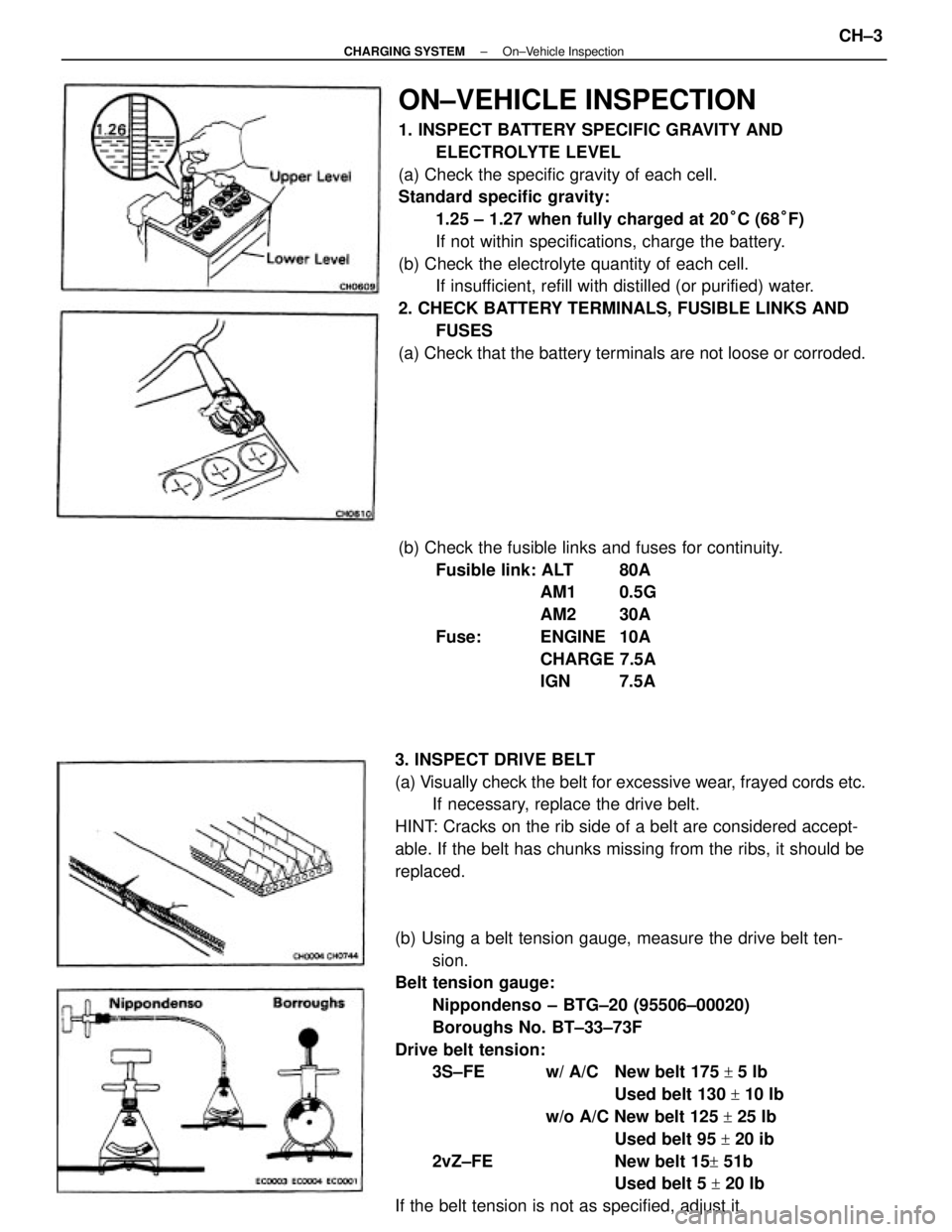
ON±VEHICLE INSPECTION
1. INSPECT BATTERY SPECIFIC GRAVITY AND
ELECTROLYTE LEVEL
(a) Check the specific gravity of each cell.
Standard specific gravity:
1.25 ± 1.27 when fully charged at 20°C (68°F)
If not within specifications, charge the battery.
(b) Check the electrolyte quantity of each cell.
If insufficient, refill with distilled (or purified) water.
2. CHECK BATTERY TERMINALS, FUSIBLE LINKS AND
FUSES
(a) Check that the battery terminals are not loose or corroded.
(b) Using a belt tension gauge, measure the drive belt ten-
sion.
Belt tension gauge:
Nippondenso ± BTG±20 (95506±00020)
Boroughs No. BT±33±73F
Drive belt tension:
3S±FE w/ A/C New belt 175
+ 5 Ib
Used belt 130
+ 10 Ib
w/o A/C New belt 125
+ 25 Ib
Used belt 95
+ 20 ib
2vZ±FE New belt 15
+ 51b
Used belt 5
+ 20 Ib
If the belt tension is not as specified, adjust it. 3. INSPECT DRIVE BELT
(a) Visually check the belt for excessive wear, frayed cords etc.
If necessary, replace the drive belt.
HINT: Cracks on the rib side of a belt are considered accept-
able. If the belt has chunks missing from the ribs, it should be
replaced.(b) Check the fusible links and fuses for continuity.
Fusible link: ALT 80A
AM1 0.5G
AM2 30A
Fuse: ENGINE 10A
CHARGE 7.5A
IGN 7.5A
± CHARGING SYSTEMOn±Vehicle InspectionCH±3
Page 1024 of 2389

TROUBLESHOOTING
TROUBLESHOOTING HINTS
1. Engine troubles is usually not caused by the EFI system.
When troubleshooting, always first check the condition of
the other systems.
(a) Electronic source
wBattery
wFusible links
wFuses
(b) Body ground
(e) Fuel supply
wFuel leakage
wFuel filter
wFuel pump
(d) Ignition system
wSpark plugs
wHigh±tension cords
wDistributor
wIgnition coil
wIgniter
(e) Air induction system
wVacuum leaks
(f) Emission control system
wPCV system
wEGR system
(g) Others
wIgnition timing (ESA system)
wdle speed (ISC system)
wetc.
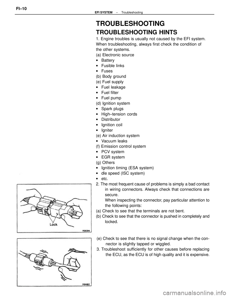
2. The most frequent cause of problems is simply a bad contact
in wiring connectors. Always check that connections are
secure.
When inspecting the connector, pay particular attention to
the following points:
(a) Check to see that the terminals are not bent.
(b) Check to see that the connector is pushed in completely and
locked.
(e) Check to see that there is no signal change when the con-
nector is slightly tapped or wiggled.
3. Troubleshoot sufficiently for other causes before replacing
the ECU, as the ECU is of high quality and it is expensive.
± EFI SYSTEMTroubleshootingFI±10
Page 1047 of 2389
ON±VEHICLE INSPECTION
1. CHECK FUEL PUMP OPERATION
(a) Turn the ignition switch ON.
NOTICE: Do not start the engine.
(b) Using SST, connect terminals +B and FP of the check con-
nector.
SST 09843±18020
(e) Turn the ignition switch OFF.
If there is no pressure, check the following
parts:
wFusible links
wFuses (ER 15 A, IGN 7.5 A)
wER main relay
wFuel pump
wECU
wWiring connections (e) Check that there is pressure in the hose from the fuel
filter.
HINT: At this time, you will hear fuel return noise.
(d) Remove SST.
SST 09843±18020
± EFI SYSTEMFuel System (Fuel Pump)FI±70