1986 CHEVROLET CORVAIR belt
[x] Cancel search: beltPage 5 of 56
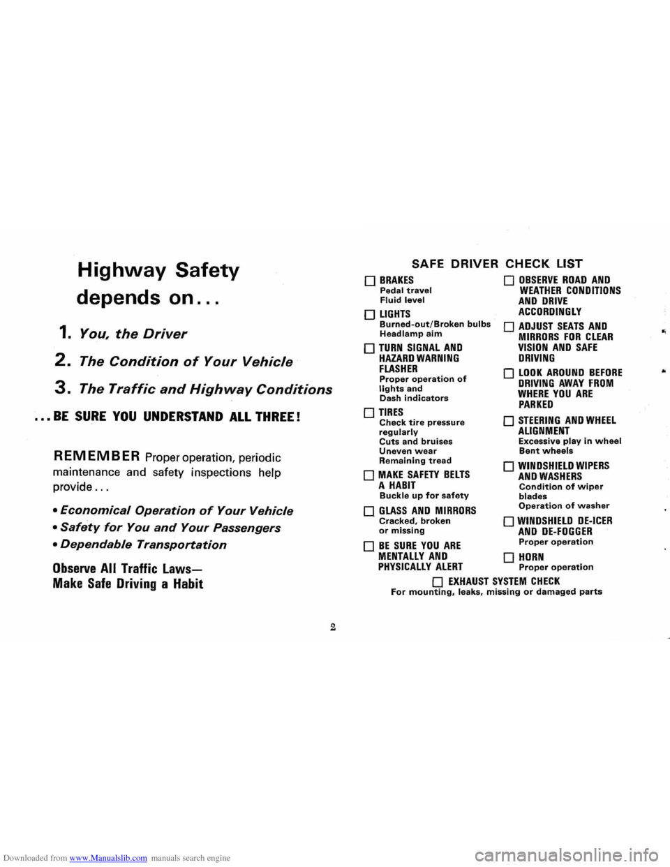
Downloaded from www.Manualslib.com manuals search engine Highway Safety
depends on ...
1. You, the Driver
2. The Condition of Your Vehicle
3. The Traffic and Highway Conditions
••• BE SURE YOU UNDERSTAND ALL THREE!
REMEMBER Proper operation, periodic
maintenance and safety inspections help
provide
...
• Economical Operation of Your Vehicle
• Safety for You and Your Passengers
• Dependable Transportation
Observe All Traffic Laws
Make Safe Driving a Habit
2
SAFE DRIVER CHECK LIST
o BRAKES Pedal travel Fluid level
o LIGHTS Burned-out/Broken bulbs Headlamp aim
o TURN SIGNAL AND HAZARD WARNING FLASHER Proper operation of lights and Dash indicators
o TIRES Check tire pressure regularly Cuts and bruises Uneven wear Remaining tread
o MAKE SAFETY BELTS A HABIT Buckle up for safety
o GLASS AND MIRRORS Cracked, broken or missing
o BE SURE YOU ARE
o OBSERVE ROAD AND WEATHER CONDITIONS AND DRIVE ACCORDINGLY
o ADJUST SEATS AND MIRRORS FOR CLEAR VISION AND SAFE DRIVING
o LOOK AROUND BEFORE DRIVING AWAY FROM WHERE YOU ARE PARKED
o STEERING AND WHEEL ALIGNMENT Excessive play in wheel Bent wheels
o WINDSHIELD WIPERS AND WASHERS Condition of wiper blades Operation of washer
o WINDSHIELD DE-ICER AND DE-FOGGER Proper operation
MENTALLY AND 0 HORN PHYSICALLY ALERT Proper operation
o EXHAUST SYSTEM CHECK For mounting, leaks, missing or damaged parts
Page 8 of 56
Downloaded from www.Manualslib.com manuals search engine STANDARD NO. III Rearview Mirrors
Purpose and Scope. This standard specifies requirements for
rearview mirrors to provide the driver with a clear and rea
sonably unobstmcted view to the rear.
STANDARD NO. 203 Impact Protection for the Driver From the Steering Control System Purpose and Scope. This standard specifies requirements for
steering control systems that will minimize chest, neck, and facial injuries to the driver as a result of impact.
STANDARD NO. 204
Steering Control Rearward Displacement
Purpose and Scope. This standard specifies requirements
limiting the rearward displacement of the steering control
into the passenger compartment to reduce the likelihood of chest, neck, or head injury.
STANDARD NO. 205 Glazing Materials
Purpose and Scope. This standard specifies requirements
for glazing materials to reduce lacerations to the face, scalp, and neck, and to minimize the possibility of occupants being
thrown through the vehicle windows in collisions.
STANDARD NO. 206 Door Latches and Door Hinge Systems Purpose and Scope. This standard specifies load require
m ents for door latches and door hinge systems to minimize
the probability of occupants being thrown from the vehicle
in a collision.
STANDARD NO. 207 Anchorage of Seats Purpose and Scope. This standard establishes requirements
for seats, their attachment assemblies, and their installation
to minimize the possibility of failure by forces acting on the seat as a result of vehicle impact.
5
STANDARD NO. 208
Seat Belt Installations
Purpose and Scope. This standard establishes requirements
for seat belt installations.
STANDARD NO. 2090
Seat Belt Assemblies
Purpose and Scope. This standard specifies requirements
for seat belt assemblies.
STANDARD NO. 210
S ea t Belt Assembly Anchorages
Purpose and Scope. This standard specifies the requirements
for seat belt assembly anchorages to ensure proper location
for effective occupant restraint and reduce the likelihood
of failure in collisions.
STANDARD NO. 211
Wheel Nuts, Wheel Discs, and Hub Caps
Purpose and Scope. This standard precludes the use of wheel nuts, wheel discs, and hub caps that constitute a hazard to
pedestrians and cyclists .
STANDARD NO. 301 Fuel Tanks, Fuel Tank Filler Pipes, and Fuel Tank Con-
nections
Purpose
and Scope. This standard specifies requirements
for the integrity and security of fuel tanks, fuel tank filler
pipes, and fuel tank connections to minimize fire hazard as
a result of collision.
PUBLIC LAW 87·637 (1962) * An Act to provide that hydraulic brake fluid sold or shipped in commerce for use in motor vehicles shall meet cer
tain specifications prescribed by the Secretary of Commerce. The requirements of this law were issued as standards when the National Traffic and Motor Vehicle Safety Act of 1966
was enacted.
"The Sea t (Lap) Belt and Brak e fluid standards are applicable
to all 1968 models of affected vehicles.
Page 17 of 56
Downloaded from www.Manualslib.com manuals search engine operating, except the GEN-FAN indicator rna)' flicker
when
engine is idling.
CAUTION: If either of these indicators light
while .
car is being. -driYen, immediately follow the
procedure outlined .vnder "EMERGENCY OPER
ATING INSTRUCTIONS," so car may be driyen
to the nearest service facility.
BRAKE SYSTEM WARNING LIGHT
This dual purpose indicator light operates as
follows:
With parking brake applied the red light will light
when
the ignition switch is turned on.
As a dual service brake system warning, the red
light will come on when the brake pedal is depressed
if low pressure has developed in either the front or
rear brake system. Have your authorized Chevrolet
dealer locate and correct the trouble immediately.
EMERGENCY OPERATING INSTRUCTIONS
(To be followed if either
TEMP-PRESS or GEN-FAN indi
cators
light while car is being
driven.)
1. Set heoter FAN and HEAT
controls to full "ON" positions.
14
(If equipped with air conditioning, turn air condi
tioning
COOL switch to OFF.)
NOTE: After setting the heater controls, leave
them in that position until cause of trouble is
corrected.
2.
Stop the car a -s , soon as driving conditions permit.
furn ignition
key to OFF to stop engine but turn
key
back to·-PNso heoter blower will continue
to
cool engine.
3. Check for broken fan belt or belt off pulleys or
engine low oil level. If only GEN-FAN indicator
is lighted, belt is not broken or off pulleys and en
gine oil level is satisfactory, car can be driven at
slow speeds; however, generator must be checked
and serviced as soon as possible.
4. If trouble is found to be a broken fan belt or belt
off pulleys, wait approximately five minutes, start
engine and drive car at no more than 25 miles per
hour until TEMP-PRESS indicator comes on, then
repeat Step 2.
NOTE: The GEN-FAN indicator will stay on until
fan
belt is installed.
5. Repeat Step 4 as necessary until facility is reached
where fan belt can be installed.
Page 18 of 56
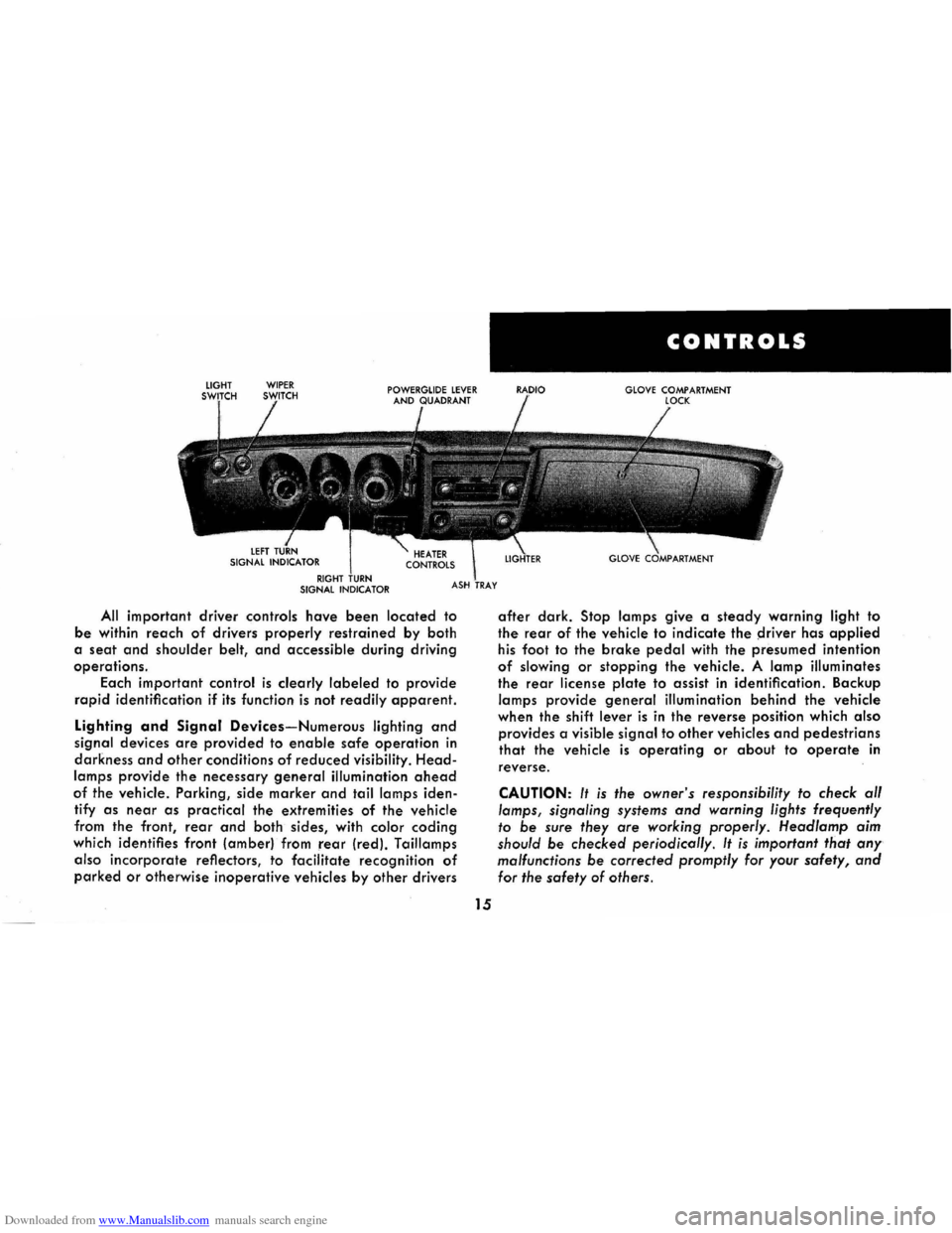
Downloaded from www.Manualslib.com manuals search engine All important driver controls have been located to
be within reach of drivers properly restrained by both
a
seat and shoulder belt, and accessible during driving
operations.
Each important
control is clearly labeled to provide
rapid identification if its function is not readily apparent.
Lighting and Signal Devices-Numerous lighting and
signal devices are provided to enable safe operation in
darkness and other conditions of reduced visibility. Head
lamps provide the necessary general illumination ahead
of the vehicle. Parking, side marker and tail lamps iden
tify
as near as practical the extremities of the vehicle
from the front,
rear and both sides, with color coding
which identifies front (amber) from rear (red). Taillamps
also
incorporate reflectors, to facilitate recognition of
parked or otherwise inoperative vehicles by other drivers
15
CONTROLS
GLOVE COMPARTMENT
after dark. Stop lamps give a steady warning light to
the rear of the vehicle to indicate the ~river has applied
his foot to the brake pedal with the presumed intention
of slowing or stopping the vehicle. A lamp illuminates
the rear license plate to assist in identification. Backup
lamps provide general illumination behind the vehicle
when the shift
lever is in the reverse position which also
provides a visible signal to other vehicles and pedestrians
that the vehicle is operating or about to operate in
reverse.
CAUTION: It is the owner's responsibility to check al/
lamps, signaling systems and warning lights frequently
to be sure they are working properly. Head/amp aim
should
be checked periodicol/y. It is important that any
malfunctions be corrected promptly for your safety, and
for the safety of others.
Page 27 of 56
Downloaded from www.Manualslib.com manuals search engine The bucket seats are adjusted in exactly the same
manner. The seat control lever
for each seat is located
beneath the outer edge of the seat (toward the door).
Underneath the seat trim are strong steel seat struc
tures,
anchored firmly to the body. The seats and
anchorages are strong enough to prevent deformation
during low-speed impacts, but are designed in such a way that they absorb some energy by yielding to a de
gree during certain more severe higher-speed impacts.
Seat Back Lock
Folding seat backs are equipped with seH-latching
mechanisms
and release controls designed for the con
venience of entering and exiting passengers.
The release
knob is located at the lower rear of
each backrest nearest the door. lift the knob upward,
then push the seatback forward. The lock will latch
when the
seatback returns to its upright position.
OCCUPANT RESTRAINT BELTS
Suitable occupant restraints are available on all 1968
Corvairs. Worn properly, lap and shoulder belts reduce
the chances
of death or serious injury in the event of cert.ain types of accidents. Get into the habit of using
these restraints,
and using them properly, every single
time you
enter your car. Insist that your passengers use
them,
too. * By using them correctly, you give the belts
a chance
to help prevent injuries and perhaps even
save a
life.
·Shoulder belts should not be worn by persons less thon approximately 55 inches in height.
24
Lap Belts
Lap belts provide added security and comfort for
you and your passengers . Lap belts are standard equip
ment for all seating positions on all models. Proper use
and care of these belts will assure continuance of this
security.
After the front seat has been adjusted to the satis
faction of the driver, grasp the buckle end and the flat
metal "eye" end of your individual belt assembly and
position the belt across the pelvic area as LOW ON THE
PELVIS AS POSSIBLE. Insert the metal eye into the open
end of the buckle until an audible snap is heard. Make
sure the connection is secure and adjust the belt to a
SNUG FIT by pulling on the end of the belt protruding
from the buckle . The snug and low positions are essential
in
order that the force exerted by the lap belt in a colli
sion may be spread over the strong pelvic bone and not
across the soft abdominal area. For retractor equipped
belts, pull retractor half of the belts to a solid stop to
make sure that the belt webbing is completely unwound
from the retractor drum, then connect the belt and make
the necessary adjustments
at the buckle for proper fit. To
release the belts, simply depress the release
tab or button
located on the center of the buckle.
CAUTION: Never use the same belt for more than one
person at a time. Be sure to avoid: (aJ wearing a lap belt
loosely or with slack
in the system; and (bJ wearing the
belt with the
webbing wound around the retractor drum.
Page 28 of 56
Downloaded from www.Manualslib.com manuals search engine Shoulder Belts
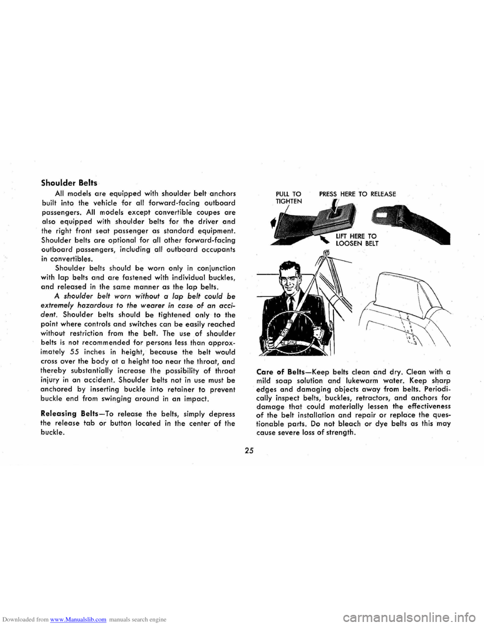
All models are equipped with shoulder belt anchors
built into the vehicle for all forward-facing outboard
passengers. All models except convertible coupes are
also equipped with shoulder belts for the driver and
the right front seat passenger as standard equipment.
Shoulder belts are optional for all other forward-facing
outboard passengers, including all outboard occupants
in convertibles.
Shoulder belts should
be worn only in conjunction
with
lap belts and are fastened with individual buckles,
and released in the same manner as the lap belts.
A shoulder belt worn without a lap belt could be
extremely hazardous to the wearer in case of an acci
dent.
Shoulder belts should be tightened only to the
point where controls and switches can be easily reached
without restriction from the belt. The use of shoulder
belts
is not recommended for persons less than approx
imately 55 inches in height, because the belt would
cross over the body at a height too near the throat, and
thereby substantially increase the possibility of throat
injury in an accident. Shoulder belts not in use must be
anchored by inserting buckle into retainer to prevent
buckle end from swinging around in an impact.
Releasing Belts-To release the belts, simply depress
the release tab or button located in the center of the
buckle.
25
PRESS HERE TO RELEASE
Care of Belts-Keep belts clean and dry. Clean with a
mild soap solution and lukewarm water. Keep sharp
edges and damaging objects away from belts. Periodi
cally inspect belts, buckles, retractors, and anchors for
damage that could materially lessen the effectiveness
of the belt installation and repair or replace the ques
tionable parts. Do not bleach or dye belts as this may
cause severe loss of strength.
Page 29 of 56
Downloaded from www.Manualslib.com manuals search engine HEAD RESTRAINTS
Head restraints are available for the driver and front
right
passenger as factory installed options. They can be
adjusted to different heights by pulling up or pushing
down by
hand. Detents provide positive head restraint
location. Head restraints should be adjusted, within
limits of travel, to contact the center of the back of head
when the head is moved straight back.
CHILD RESTRAINT
Children in automobiles should be restrained. A
restraint system
designed by General Motors specifically
for
children is available from your dealer. If children
are traveling in a vehicle not equipped with this child
restraint system, the following precautions should be
taken:
1. Children should be placed in the rear seat. Never
allow a child to stand or kneel on the rear seat as
this raises his center of gravity.
2. Infants unable to sit up by themselves should be
restrained by placing them in a covered, padded
bassinet which is placed crossways on th·e rear
REARVIEW MIRRORS
Inside and outside rearview mirrors have been care
fully designed and located to give the driver a clear and
reasonably unobstructed view of the rear of the car. It
is not intended that these mirrors be used for operation
in reverse gear, or for surveillance of conditions close
to
the back of the car. It is suggested that the driver
turn his
head and look close to the back for backing
26
seat. The bassinet should be securely restrained
with the regular vehicle seat belt. An alternative
method is to position the bassinet crossways in the
vehicle so
that it rests against the back of the front seat. ..
3. When a child is old enough to sit up by himself in
a car, he should sit on a firm cushion and use the
conventional lap belt to restrain him at the pelvis.
The cushion should be as firm as practical and
enable the child to look horizontally out of the car
windows.
4. The use
of the cushion should be discontinued as
soon as the child is old enough to see out of the
car windows without it.
5. Do not use shoulder belts on children shorter than approximately 55 inches in height.
6. If a child must stand, he should stand on the floor
directly behind the front seat. This will minimize
the possibility of his being thrown from the rear
compartment during a sudden stop. However, this
method
should be used only if more complete re
straint cannot be used.
operations, and survey the area to the immediate rear
of the car prior to entering the car for the backing
operation. The outside mirror and mounting is free of
sharp points or edges that could contribute to injury of
pedestrians. The inside rearview mirror incorporates provisions
for
vertical as well as tilt adjustments to provide better
positioning for the driver. The mounting is designed to
Page 31 of 56
Downloaded from www.Manualslib.com manuals search engine ing the front corner of the top and rotating the top for
ward until top rests on windshield header.
The locking handles are then rotated outboard
which engages the lock hooks to the striker assembly
located on the windshield header.
Installing the Top Boot
Remove top boot from its protective case, which is normally stored in the luggage compartment.
Grasping forward
end of the boot, slide the welt on
the
boot into the retainer located on the top of the rear
seat back panel. The boot can then be placed over the
lowered top and the metal snap fasteners on the boot
can be snapped onto the studs on the belt molding and quarter trim. Any wrinkles that may exist may be re
lieved
by sliding the forward portion of the boot to the
right or left in the retainer.
Care of Folding Top and Rear Window
The folding top should never be subiected to vola
tile cleaners or household bleaches. Frequent washing
with
neutral soap suds, lukewarm water and soft bristle
brush
is normally all that is necessary to maintain the
"Factory Fresh" look. In the event heavy soilage or
stubborn stains are encountered, a mild foaming cleanser, lukewarm water, and a soft bristle brush may be
used. If desired, the top may be supported from the
underside during the cleaning
operation. Regardless
which cleaning method is used, a generous amount of
28
rinse water is to be used as any soap that runs down
on the
body finish and allowed to dry, may cause streaks.
After cleaning,
always be sure the top is thoroughly dry before it is lowered.
The pliable plastic window, due to its texture, is sus
ceptible
to scratches and abrasions. As a result, the top
should not be lowered when the rear window is dirty.
When cleaning the
rear window, do not use a dry
cloth or volatile cleaning agents. A soft cloth moistened
with
water should be used to remove superficial dust.
When completely washing the rear window, cold or
luke warm water and a mild neutral soap suds may be
used along with a generous amount of rinse water. In
addition, the rear window can be cleaned with G.M. Plastic Cleaner available at your dealer.
A scraper should never be used for removing snow
or ice from the rear window. In an emergency, warm
water may be cautiously used.
NOTE: DO NOT paste any stickers or masking tape
on rear window as damage will result.
ENGINE COMPARTMENT
• To open: Push up the lid release while lifting the lid.
Lift the lid all the way up, then release.
• To close: Lift up on lid, unlock the support arm catch
lock, then lower the lid. Drop the lid the last six