1986 CHEVROLET CORVAIR ignition
[x] Cancel search: ignitionPage 20 of 56
Downloaded from www.Manualslib.com manuals search engine If the system is not functioning properly, a legal hand
signal should be given, since failure to indicate a turn
is considered a moving traffic violation in many states.
Always signal for a turn
at a reasonable distance before actu 'ally making it.
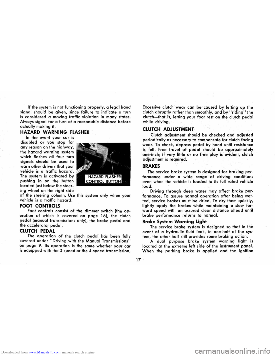
HAZARD WARNING FLASHER
In the event your car is
disabled or you stop for
any reason on the highway,
the
hazard warning system
which flashes all four turn
signals should
be used to
warn
other drivers that your
vehicle
is a traffic hazard.
The system is activated by
pushing
in on the button
located just
below the steer
ing wheel on the right side
of the steering column. Use this system only when your
vehicle
is a traffic hazard.
FOOT CONTROLS Foot controls consist of the dimmer switch (the op
eration of which is covered on page 16), the clutch
pedal (manual transmissions only), the brake pedal and
the accelerator pedal.
CLUTCH PEDAL The operation of the clutch pedal has been fully
covered under
"Driving with the Manual Transmissions"
on
page 9. Its operation is the same whether your car
is equipped with the 3-speed or the 4-speed transmission. Excessive
clutch
wear can be caused by letting up the
clutch abruptly
rather than smoothly, and by "riding" the
clutch-that is, letting your foot rest on the clutch pedal
while driving .
CLUTCH ADJUSTMENT
Clutch adjustment should be checked and adjusted
periodically as necessary to compensate for clutch facing
wear. To check, depress pedal.by hand until resistance
is felt. Free travel of pedal should be approximately
one-inch;
if very little or no free play is evident, clutch
adjustment
is required.
BRAKES
The service brake system is designed for braking per
formance under a wide range of driving conditions
even when the vehicle
is loaded to its full rated vehicle
load. Driving through deep water may affect brake per
formance. To assure normal operation after being wet
ted, service brakes must be dried. To dry them quickly,
lightly
apply the brakes while maintaining a slow for"
ward speed with an assured clear distance ahead until
brake performance re'turns to normal.
Brake System Warning Light
The service brake system is designed so that in the
event of a hydraulic fluid leak,
in one-half of the sys
tem, the other half still provides some braking action.
A dual purpose brake system warning light is
located at the extreme left side of the instrument panel.
When the parking brake is applied and the ignition
17 .
Page 21 of 56
Downloaded from www.Manualslib.com manuals search engine switch is turned to the "ON" position, the warning light
glows red to indicate to the operator that the parking
brake has not been fully released. This also indicates
that the brake warning light is operational. If the light does not come on, have your Corvair Dealer correct
the trouble as soon as possible. The other function of
this light is to indicate a malfunction in the regular braking system. In the event of broken brake lines,
major brake fluid loss, air in the brake lines or a pres
sure deviation between the front · and the rear wheel
brake lines, the light will come on and stay on while
braking .
In this event, the vehicle should not be driven
until
the cause has been determined and, if necessary,
corrected.
Automatic Brake Adjusters
All Corvair models are equipped with self-adjusting
brakes which eliminates periodic brake adjustments. The
self-adjusting mechanism
is actuated, as needed, when
ever the car is moved in reverse and the brakes applied.
It is possible, however, for excessive brake pedal travel
to
develop if the required reverse movement with a
brake application does not take place during a pro
longed
period of stop and go forward driving. Should
this occur,
the car should be driven backward and for
ward with the brakes applied at the end of each direc
tional movement, until the brake pedal travel is back to
normal. If this procedure fails to restore normal pedal
travel, or if any abnormally rapid increase in pedal
travel is experienced, immediate inspection should be
made by your Authorized Chevrolet Dealer. Care should
18
be exercised to assure that full brake pedal travel can
not be obstructed by improper floor mats or other inter
fering material under the pedal.
PARKING BRAKE
The parking brake operates by cables on the rear
wheel brakes independent of the regular foot brake hydraulic system. The brake system warning light will
be "ON" whenever the parking brake is not fully re
leased and the ignition switch is "ON". Never drive the car with the parking brake engaged. .
Pull the parking brake lever as far as possible to
engage the brake. The lever will remain in the applied
position until released. To release, pull the handle to
ward the steering wheel, depress the "trigger" and
allow the handle to return to the released position. CAUTION: When leaving the car unattended, always
fully apply the parking brake.
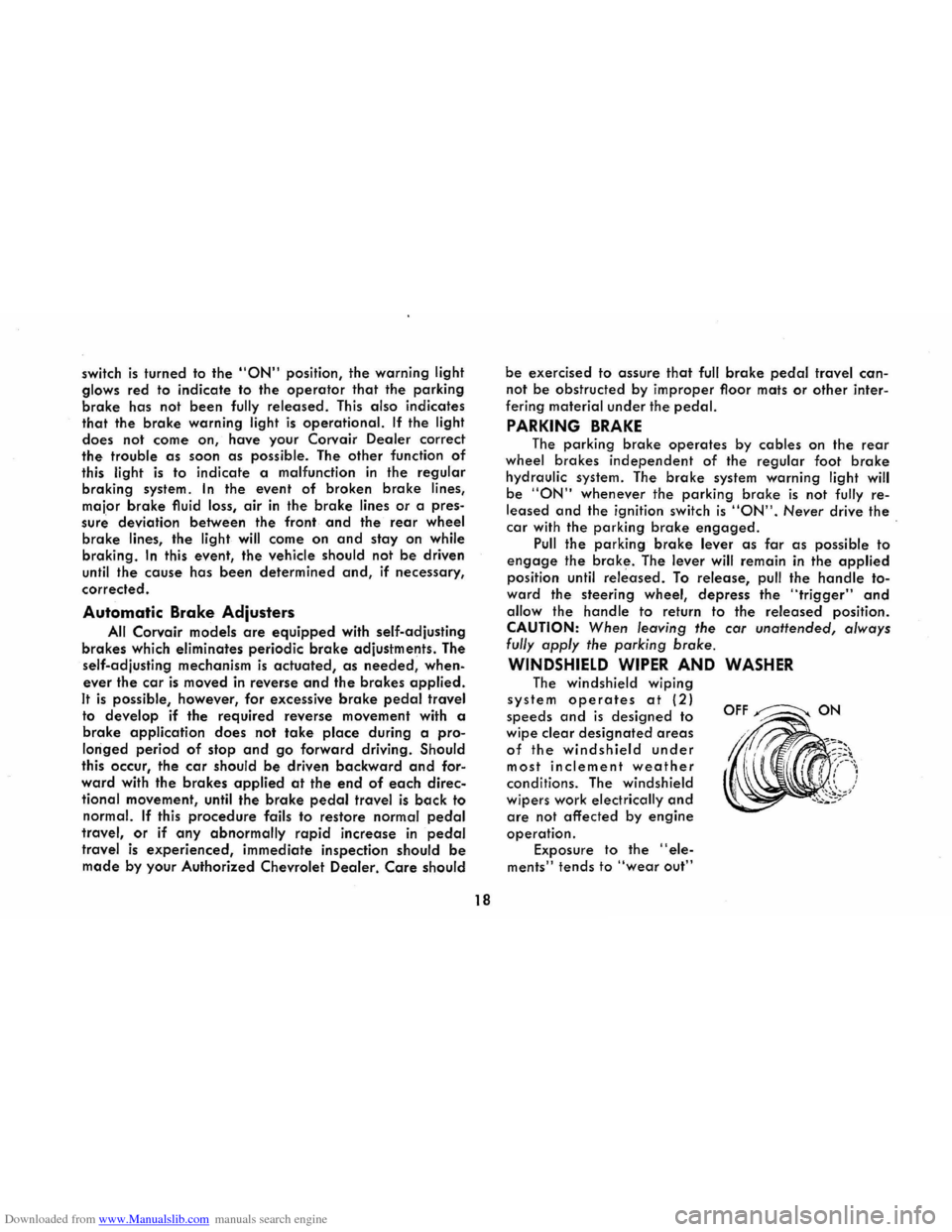
WINDSHIELD WIPER AND WASHER
The windshield wiping
system operates at (2)
speeds and is designed to
wipe clear
designated areas
of the windshield under
most inclement weather
conditions. The windshield
wipers work
electrically and
are not affected by engine
operation.
Exposure to the "ele
ments" tends to "wear out"
OFF~ON
Page 24 of 56
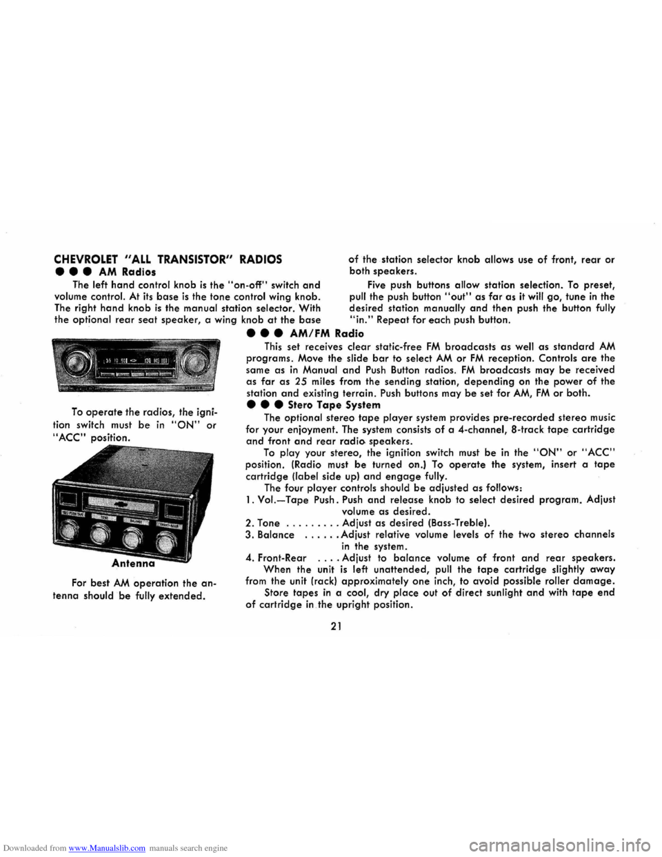
Downloaded from www.Manualslib.com manuals search engine CHEVROLET "ALL TRANSISTOR" RADIOS
••• AM Radios
of the station selector knob allows use of front, rear or
both
speakers .
The
left hand control knob is the "on-off" switch and Five push buttons allow station selection. To preset,
volume
control. At its base is the tone control wing knob. pull the push button "out" as far as it will go, tune in the
The right
hand knob is the manual station selector. With desired station manually and then push the button fully
the optional rear seat speaker, a wing knob at the base "in." Repeat for each push button .
To operate the radios, the igni
tion switch must
be in "ON" or
"ACC" position.
For best AM operation the an
tenna should be fully extended.
• • • AM/FM Radio
This set receives clear static-free FM broadcasts as well as standard AM
programs. Move the slide bar to select AM or FM reception. Controls are the
same
as in Manual and Push Button radios. FM broadcasts may be received
as far as 25 miles from the sending station, depending on the power of the
station
and existing terrain. Push buttons may be set for AM, FM or both .
• • • Stero Tape System
The optional stereo tape player system provides pre-recorded stereo music
for your enjoyment. The system consists
of a 4-channel, a-track tape cartridge
and front and rear radio speakers.
To play your stereo, the ignition switch must be in the "ON" or "ACC"
position. (Radio must be turned on.) To operate the system, insert a tape
cartridge (label side up) and engage fully.
The four player controls should be adjusted as follows:
1. Vol.-Tape Push. Push and release knob to select desired program. Adjust
volume
as desired.
2. Tone ... .
..... Adjust as desired (Bass-Treble).
3. Balance ...... Adjust relative volume levels of the two stereo channels
in the system.
4. Front-Rear .... Adjust to balance volume of front and rear speakers.
When the unit
is left unattended, pull the tape cartridge slightly away
from the unit (rack) approximately one inch, to avoid possible roller damage.
Store tapes in a cool, dry place out of direct sunlight and with tape end
of cartridge in the upright position.
21
Page 25 of 56
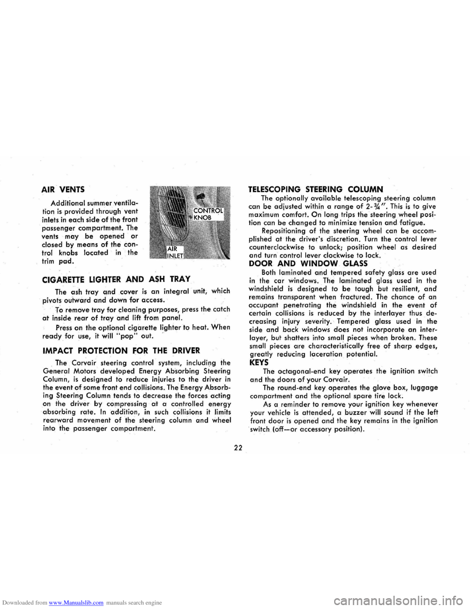
Downloaded from www.Manualslib.com manuals search engine AIR VENTS
Additional summer ventila
tion is provided through vent
inlets in each side of the front
passenger compartment. The
vents
may be opened or
closed by means of the con
trol knobs located in the
trim pad.
CIGARETTE LIGHTER AND ASH TRAY
The ash tray and cover is an integral unit, which
pivots
outward and down for access.
To
remove tray for cleaning purposes, press the catch
at inside rear of tray and lift from panel.
Press on the optional cigarette lighter to heat. When
ready for use, it will "pop" out. '
IMPACT PROTECTION FOR THE DRIVER
. The Corvair steering control system, includil)g the
General Motors developed Energy Absorbing Steering
Column,
is designed to reduce injuries to the driver in
the event
of some front end collisions. The Energy Absorb
ing Steering Column tends to decrease the forces acting
on the driver by compressing at a controlled energy
absorbing rate. In addition, in such collisions it limits
rearward movement of the steering column and wheel
into the passenger compartment.
22
TELESCOPING STEERING COLUMN
The optionally available telescoping steering column
can be adjusted
within a range of 2-%". This is to give maximum comfort. On long trips the steering wheel posi
tion can
be changed to minimize tension and fatigue. Repositioning of the steering wheel can be accom
plished
at the driver's discretion. Turn the control lever
counterclockwise to unlock; position wheel as desired
and turn control lever clockwise to lock.
DOOR AND WINDOW GLASS
Both laminated and tempered safety glass are used
in the
car windows. The laminated glass used in the windshield is designed to be tough but resilient, and
remains transparent when fractured. The chance of an
occupant penetrating the windshield in the event of
certain collisions is reduced by the interlayer thus de
creasing injury severity. Tempered glass used in the
side
and back windows does not incorporate an inter
layer, but shatters into small pieces when broken. These
small pieces
are characteristically free of sharp edges,
greatly reducing laceration potential.
KEYS
The octagonal-end key operates the ignition switch
and the doors of your Corvair.
The round-end key operates the glove box, luggage
compartment and the optional spare tire lock.
As a
reminder to remove your ignition key whenever
your vehicle is attended, a buzzer will sound if the left
front door is opened and the key remains in the ignition
switch (off-or accessory position).
Page 26 of 56
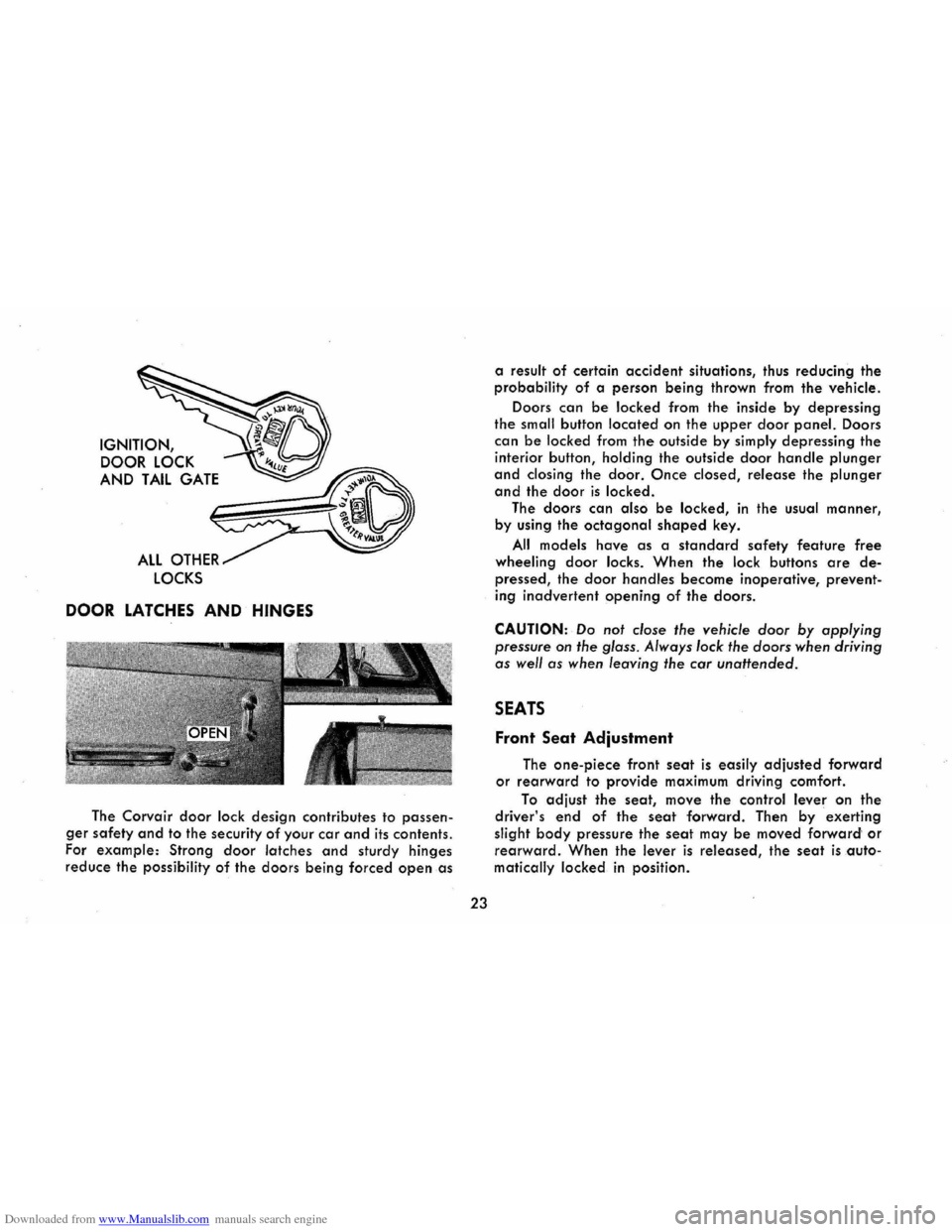
Downloaded from www.Manualslib.com manuals search engine IGNITION, DOOR
LOCK
AND TAIL GATE
ALL OTHER
LOCKS
DOOR LATCHES AND HINGES
The Corvair door lock design contributes to passen
ger safety and to the security of your car and its contents.
For
example: Strong door latches and sturdy hinges
reduce the possibility of the doors being forced open as
23
a result of certain accident situations, thus reducing the
probability
of a person being thrown from the vehicle.
Doors
can be locked from the inside by depressing
the small button located on the upper door panel. Doors
can be locked from the outside by simply depressing the
interior button, holding the outside door handle plunger
and closing the door. Once closed, release the plunger
and the door is locked.
The doors
can also be locked, in the usual manner,
by using
the octagonal shaped key.
All models have as a standard safety feature free
wheeling door locks. When the lock buttons are de
pressed, the door handles become inoperative, prevent
ing
inadvertent opening of the doors.
CAUTION: Do not close the vehicle door by applying
pressure
on the glass. Always lock the doors when driving
as well as when leaving the car unattended.
SEATS
Front Seat Adjustment
The one-piece front seat is easily adjusted forward
or rearward to provide maximum driving comfort.
To adjust the seat, move the control lever on the
driver's end of the seat forward. Then by exerting
slight
body pressure the seat may be moved forward' or
rearward. When the lever is released, the seat is auto
matically locked
in position.
Page 40 of 56
Downloaded from www.Manualslib.com manuals search engine PERIODIC MAINTENANCE AND LUBRICATION
The time or mileage intervals on the following pages
are intended as a general guide for establishing regular
maintenance and lubrication periods for your Corvair.
Sustained heavy duty or high speed operations or oper-
A WORD ABOUT VEHICLE EMISSIONS
All new 1968 Corvairs are certified by the United States Department of Health, Education and Welfare as
conforming to the requirements of the regulations for
the Control of Air Pollution from New Motor Vehicles
and New Motor Vehicle Engines.
General Motors has developed control systems which
are highly effective in reducing undesirable crankcase
and exhaust emissions. It is very important that the owner make certain that the engine is serviced regularly
in order to maintain its efficiency and to keep emissions
below maximum allowable limits.
The emission control system on
your 1968 Corvair is
relatively easy to maintain, requiring only specific serv
ices as recommended by Chevrolet. To function properly,
this system must be inspected periodically and engine
tune-up performed at specified intervals by qualified
repairmen. For ready reference, pertinent information regarding ignition timing and idle speed and fuel mix
ture specifications is shown on a sticker affixed under
the hood of your vehicle. Following the prescribed main-
37
ation under adverse conditions may necessitate more
frequent servicing. For specific recommendations for con
ditions under which you use your vehicle, consult your
authorized Chevrolet Dealer.
tenance services
will help assure cleaner air and will
provide better running, longer lasting engines for greater
all-around satisfaction, economy and performance.
POSITIVE CRANKCASE VENTILATION (P.C.V')
The Positive Crankcase Ventilation system, which is
standard equipment on your vehicle, prevents emission
of gases from the crankcase. The P .C.V. system connects
the crankcase and intake manifold of the engine and
crankcase gases are returned through this system to the
combustion
chamber where they are burned. Periodic
inspection
and required servicing of your P.C.V. system
assures a cleaner, better-performing, longer-lasting
engine. A plugged P.C.V. system results in a loss of
crankcase ventilation which can cause condensation of
blow-by gases in the crankcase, resulting in the forma
tion of acids, sludge build-up and oil dilution. This also
results in
an increase in exhaust emissions due to car
buretor enrichment. Every 12,000 miles or 12 months,
whichever occurs first, the PCV valve should be replaced.
Page 41 of 56
Downloaded from www.Manualslib.com manuals search engine Also, all hoses, fittings and the inlet air filter should be
inspected, cleaned and replciced if necessary.
NOTE: If the positive crankcase ventilator valve should
become
dogged, the engine idle will be adversely
affect~d. Therefore, if the engine idle becomes too slow
or rough, the ventilator valve should be checked before
any carburetor ad;ustments are made to compensate for
the trouble.
AIR INJECTION REACTOR (A.I.R.l
The Air
Injection Reactor system is designed to re
duce .air pollution caused by exhaust emissions. It is entirely separate from the Positive Crankcase Ventilating
system. The Air
Injection Reactor system operates by
oxidizing (or burning) the
hydrocarbons and carbon
monoxide as they are expelled from the combustion
chamber into the exhaust. A positive displacement air
pump, driven by the engine, compresses clean frltered
air, which
is distributed and injected at the exhaust part
of each cylinder. This fresh air mixes with the hot exhaust
gases and promotes further oxidation (or burning) of
both hydrocarbons and carbon monoxide by converting
some
of them to carbon dioxide and water. This does not
reduce the danger of inhaling carbon monoxide in con
frned areas. See page 7 for carbon monoxide warning.
Supplementing
the air pump a special carburetor and
distributor plus related components are required.
The Air
Injection Reactor system should have the A.I.R. pump filter serviced and the drive belt inspected
for
wear and tension every 12 months or 12,000 miles,
38
whichever occurs frrst. In addition, complete effectiveness
of the system, as well as full power and performance,
depends upon idle speed, ignition timing, and idle fuel
mixture being
set according to specifrcation. A quality
tune-up which includes
these adjustments should be per
formed periodically to assure normal engine efficiency,
operation and performance.
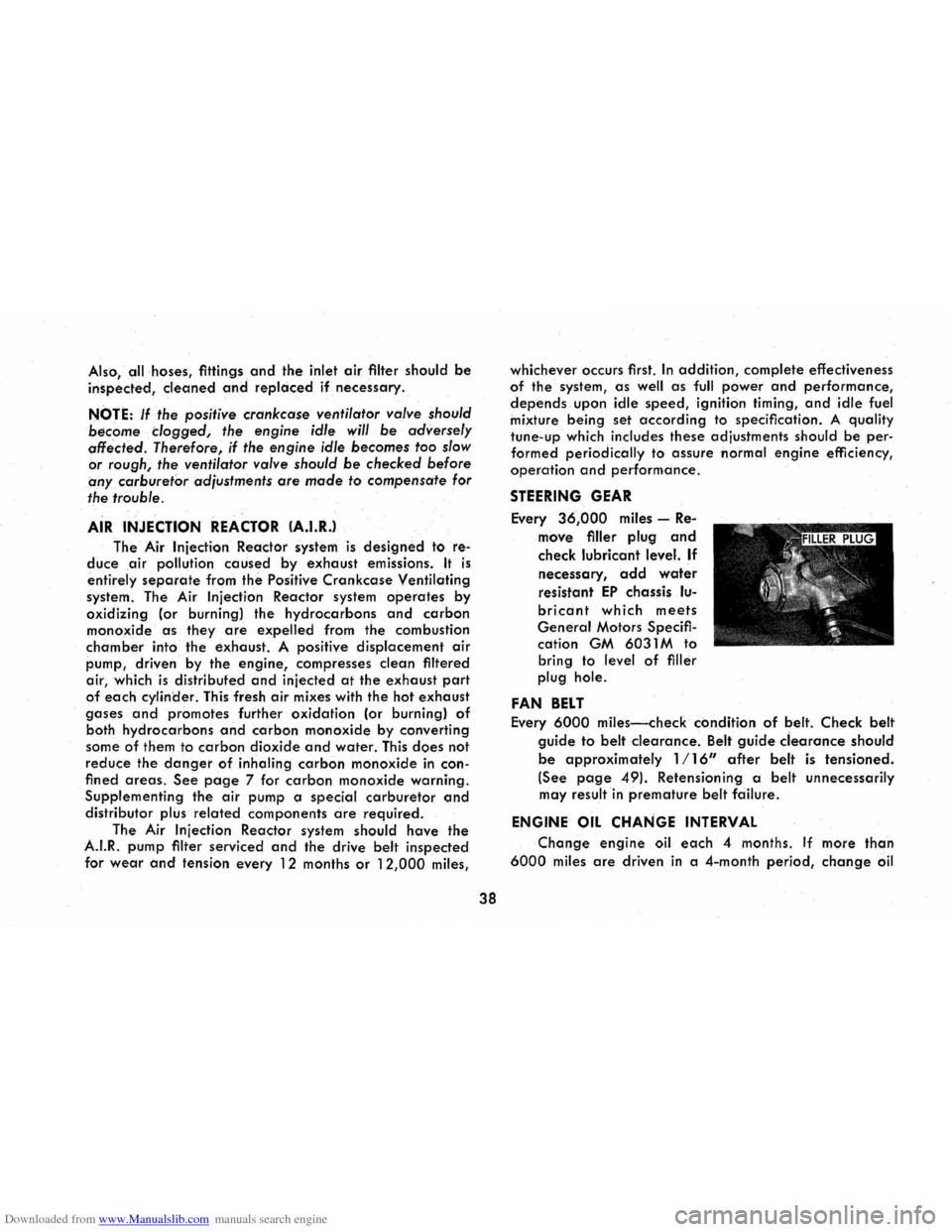
STEERING GEAR
Every 36,000 miles -Re
move frller plug and
check lubricant level. If
necessary, add water
resistant EP chassis lu
bricant which meets
General Motors Specifr
cation GM 6031 M to
bring to level
of frller
plug hole.
FAN BELT
Every 6000 miles-check condition of belt. Check belt
guide to belt clearance. Belt guide ciearance should
be approximately 1/16" after belt is tensioned.
(See page 49). Retensioning a belt unnecessarily
may result
in premature belt fciilure.
ENGINE OIL CHANGE INTERVAL
Change engine oil each 4 months. If more than
6000 miles are driven in a 4-month period, change oil
Page 45 of 56
Downloaded from www.Manualslib.com manuals search engine AIR CLEANER
CAUTION: In addition to its function of filtering air
drawn into
the engine through the carburetor, the air
cleaner also acts as
a flame arrester in the event the
engine backfires. Because backfiring
may cause fire in
the engine compartment, the air cleaner should be in
stalled at all times unless its removal is necessary for
repair or maintenance services.
Paper Element Type
The oil-wetted paper element is a long-life efficient air
cleaner and should not require replacement before
24,000 miles except under extreme adverse condi
tions .
Inspect air cleaner at 12,000 miles for dust leaks,
holes
or other damage, replace if necessary . If
condition is satisfactory, rotate element 1800 from
originally installed position. Replace
at 24,000 miles.
Under extreme
adverse conditions inspect every 6,000 miles.
Oil Bath Type
Every 12,000 miles-Inspect and clean if necessary.
Refill with SAE 50 engine oil when lowest anticipated
temperature is above freezing; use SAE 20 if below
freezing.
BATTERY (ENERGIZER)
Every 6,000 miles-Clean and oil battery terminals and
oil felt washer. Check fluid level frequently. Keep
filled with distilled water to level of split ring in
42
vent tube. The electrolyte level indicator in the cap
of one cell will glow if the fluid level is low. In this
case each cell should be checked.
CAUTION: Since normal battery or Energizer
chemical action generates hydrogen gas which
is highly explosive when mixed with air, never
expose the battery to an open flame or electric
spark. Also, avoid getting battery fluid, which
is a sulfuric acid solution, on skin, on clothing
or other fabrics, or on painted surfaces . Eye
protection should
be worn while working on the
battery for
any reason.
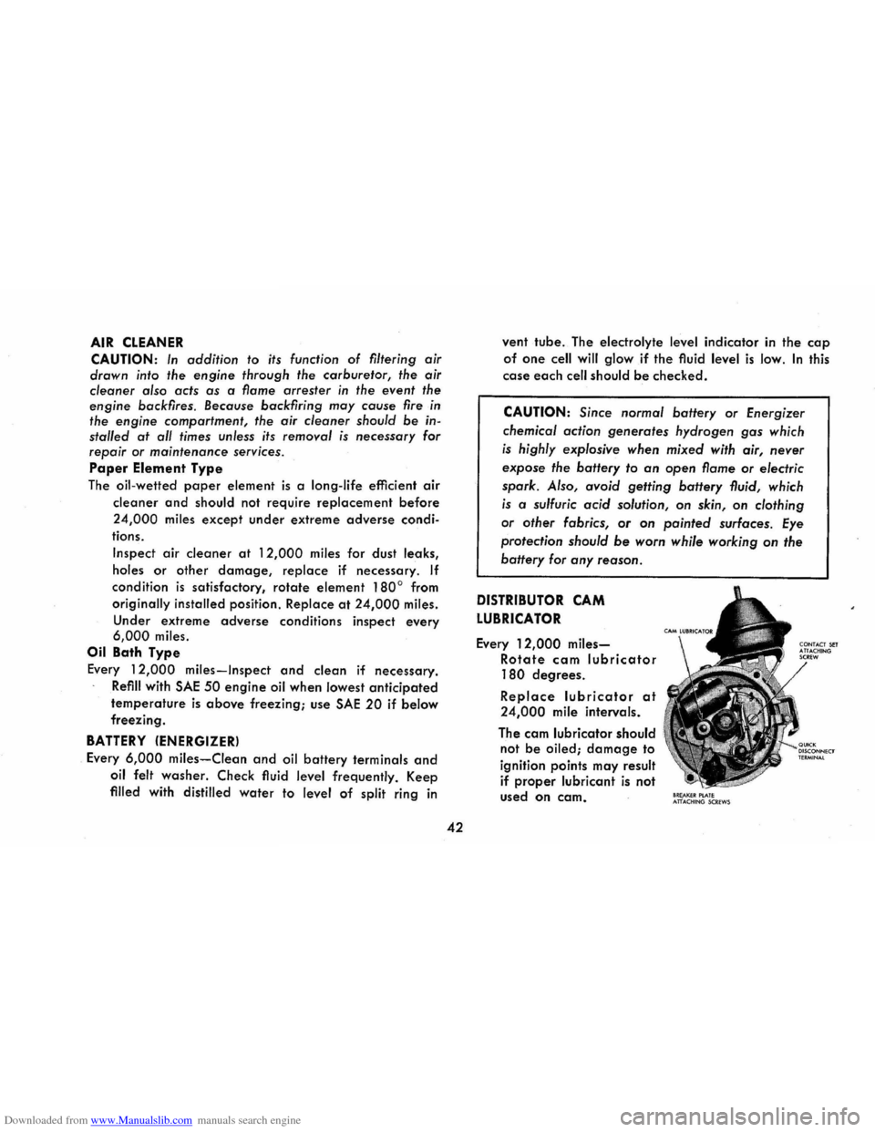
DISTRIBUTOR CAM
LUBRICATOR
Every 12,000 miles
Rotate cam lubricator
180 degrees.
Replace lubricator at
24,000 mile intervals.
The cam lubricator should
not
be oiled; damage to
ignition points may result
if
proper lubricant is not
used
on cam. 8RE,AKEIt PlATE ATTACHtNG SCREWS