Page 492 of 885
'l
FA..12FRONT AXLE AND SUSPENSION - Axle Hub
(b) lnsert the bolts from the front side and align the
matchmarks of the camber adjust cam.
(c) Torque the bolts.
Torque: 1,450 kg-cm (105 ft-lb, 142 N'ml
5. INSTALL BRAKE CALIPER TO STEERING KNUCKLE
Torque the bolts.
Torque: 970 kg-cm (70 ft-lb, 95 N.ml
#
6. CONNECT TIE ROD END TO STEERING KNUCKLE
Torque the nut and secure it with a new cotter pin.
Torque: 6O0 kg:cm (43 ft-lb, 59 N.m)
'\i. i
tr,bWVii
i
TOROUE BEAfriG LOCK NUT AND INSTALL LOCK
NUT CAP AND;COTTER?IN
(a) Torqrle the lock nut wtrile depiUs.s.lng the brake pedal.
Torque: 1,900 kg-cm (137 ft-lb, f86 N.m)
(b) Install the lock nut cap affittsing plieib,.install a new
7.
cott*. pin.
8.
+
CHECK FRONT WHEEL ALIGNMENT f$6e page FA-3)'-*+***n,. it'., . .i .:)".4..,,'i".: "
Il.I
f,'l.
Page 500 of 885
FA-20FRONT AXLE AND SUSPENSION - Front Shock Absorber
w/o PS
w/ PS and 4WD
(c) Remove the three nuts holding the shock absorber to
the body.
(d Remove the shock absorber assembly.
CAUTION: Cover the drive shaft boot with cloth to
avoid damage.
3. CLAMP SHOCK ABSORBER IN VISE
Install a bolt and nuts to the bracket at the lower portion of
the shock absorber shell and secure it in a vise.
4, REMOVE COIL SPRING
(d Using SST, compress the coil spring.
ssr 09727 -22032
(b) Hold the suspension with a screwdriver or such so
that it will not turn, and then remove the support nut.
(c) Remove the suspension support, spring seat, spring
and dust cover.
tr-;
W
Page 526 of 885

-
RA.l8REAR AXLE AND SUSPENSION - Rear Suspension (FWD)
e F I
ry
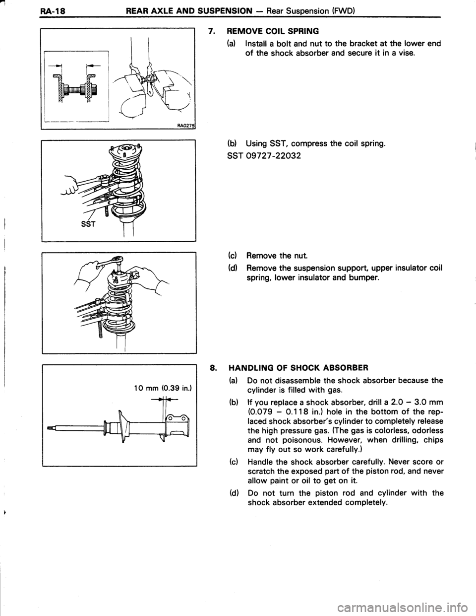
7. REMOVE COIL SPRING
(d Install a bolt and nut to the bracket at the lower end
of the shock absorber and secure it in a vise.
(d Using SST, compress the coil spring.
ssr 09727-22032
(c) Remove the nut.
(d) Remove the suspension support, upper insulator coil
spring, lower insulator and bumper.
8. HANDLING OF SHOCK ABSORBER
(a) Do not disassemble the shock absorber because the
cylinder is filled with gas.
(b) lf you replace a shock absorber, drill a 2.0 - 3.0 mm
(0.079 - 0.118 in.) hole in the bottom of the rep-
laced shock absorber's cylinder to completely release
the high pressure gas. ffhe gas is colorless, odorless
and not poisonous. However, when drilling, chips
may fly out so work carefully.)
(c) Handle the shock absorber carefully. Never score or
scratch the exposed part of the piston rod, and never
allow paint or oil to get on it.
(d) Do not turn the piston rod and cylinder with the
shock absorber extended completely.
1O mm (0.39 in.)
Page 555 of 885
REAR AXLE AND SUSPENSION - Four Link Type Rear Suspension (4WD)RA.47
Chamfer
RAO343
2. INSTALL BUSHING
Using SST and a press, press a new bushing into the
lateral control rod.
ssT 0971 0-14012
NOTE: Do not use a lubricant when pressing in the bush-ing.
INSTALLATION OF LATERAL CONTROL ROD
1. INSTALL LATERAL CONTROL ROD TO BODY
(a) Raise the axle housing until the housing is free from
the stands.
(b) Installthe lateralcontrol rod to the body with the nut.
INSTALL LATERAL CONTROL ROD TO REAR AXLE
HOUSING
(d Consecutively install the washer, bushing, spacer,
lateral control arm, bushing, washer and nut on the
rear axle housing.
(b) Remove the stands and bounce the car to stabilize
the suspension.
2.
Page 580 of 885
BRAKE SYSTEM - Front BrakeBR-2;1,,,":l-.,
4. INSTALL COLLAR, DUST BOOT AND CYLINDER
SLIDE BUSHING
(a) Installthe collar and dust boot into the brake "VlinOer.'"'f,.@,*;
(b) Check that the boot is secured firmly to the brlkp
cylinder groove. ';1"t,
(c) Install the bushing into the boot.
(d) Check that the boot is secured firmly to the bushing
groove.
t:' t;
INSTALLATION OF CYLINDER JS .t
(See page BR-l61
1. INSTALL PADS ,,,\$,(See steps 7 to 9 on pag6s BR-17 and 18)-i
2. INSTALL CYLINDER(See step 11 on page BR-271
3. INSTALL FLEXIBLE HOSE TO BRAKE CYLINDER
Torque: 235 kg-cm (17 ft-lb, 23 N.m)
4. CONNECT FLEXIBLE HOSE TO BRAKE TUBE
Using SST, connect the flexible hose.
ssT 09751 -3601 1
Torque: 155 kg-cm (11 ft-lb, 15 N.ml
5. FILL BRAKE RESERVOIR WITH BRAKE FLUID
AND BLEED BRAKE SYSTEM (See page BR-71
SST