1985 FORD GRANADA low oil pressure
[x] Cancel search: low oil pressurePage 120 of 255
engine coolant temperature sensor. The
crankshaft speed/position sensor is activated
by a toothed disc on the rear of the crankshaft,
inside the cylinder block. The disc has 35
equally spaced teeth (one every 10°), with a
gap in the 36th position. The gap is used by
the sensor to determine the crankshaft
position relative to Top Dead Centre (TDC) of
No 1 piston.
The ignition advance is a function of the
ESC II module, and is controlled by vacuum.
The module is connected to the carburettor by
a vacuum pipe, and a transducer in the
module translates the vacuum signal into an
electrical voltage. From the vacuum signal, the
module determines engine load; engine speed
and temperature are determined from the
crankshaft speed/position sensor and the
engine coolant temperature sensor. The
module has a range of spark advance settings
stored in the memory, and a suitable setting is
selected for the relevant engine speed, load
and temperature. The degree of advance can
thus be constantly varied to suit the prevailing
engine speed and load conditions.
On DOHC fuel-injected engines, a
development of the EEC IV (Electronic Engine
Control IV) engine management system is
used to control both the ignition and fuel-
injection systems. The EEC IV module receives
information from a crankshaft speed/position
sensor (the same as that fitted to the
carburettor models), a throttle position sensor,
an engine coolant temperature sensor, a fuel
temperature sensor, an air charge temperature
sensor, a Manifold Absolute Pressure (MAP)
sensor, and a vehicle speed sensor (mounted
on the gearbox). Additionally, on models with
a catalytic converter, an additional input is
supplied to the EEC IV module from an
exhaust gas oxygen (HEGO) sensor. On
models with automatic transmission,
additional sensors are fitted to the
transmission to inform the EEC IV module
when the transmission is in neutral, and when
the downshift is being operated.
The module provides outputs to control the
fuel pump, fuel-injectors, idle speed, ignition
system and automatic transmission .
Additionally, on models with air conditioning,
the EEC IV module disengages the air
conditioning compressor clutch when starting
the engine or when the engine is suddenly
accelerated. On models fitted with a catalytic
converter, the EEC IV module also controls the
carbon canister purge solenoid valve.
Using the inputs from the various sensors,
the EEC IV module computes the optimum
ignition advance, and fuel-injector pulse
duration to suit the prevailing engine
conditions.
On 2.4 & 2.9 litre V6 engines, the system
operates in much the same way as that fitted
to the DOHC fuel-injected engine, noting the
following points.
a)There is no crankshaft speed/position
sensor.
b)The vehicle speed sensor is only fitted to
models equipped with a catalytic
converter.Precautions
ESC II module
Although it will tolerate all normal under-
bonnet conditions, the ESC II module may be
adversely affected by water entry during
steam cleaning or pressure washing of the
engine bay.
If cleaning the engine bay, therefore, take
care not to direct jets of water or steam at the
ESC II module. If this cannot be avoided,
remove the module completely, and protect its
multi-plug with a plastic bag.
Ignition system HT voltage
Take care to avoid receiving electric shocks
from the HT side of the ignition system. Do not
handle HT leads, or touch the distributor or
coil, when the engine is running. When tracing
faults in the HT system, use well insulated
tools to manipulate live leads. Electronic
ignition HT voltage could prove fatal.
Electronic ignition systems
General
Further details of the various systems are
given in the relevant Sections of this Chapter.
While some repair procedures are given, the
usual course of action is to renew the
component concerned. The owner whose
interest extends beyond mere component
renewal should obtain a copy of the
Automobile Electrical & Electronic Systems
Manual, available from the publishers of this
manual.
It is necessary to take extra care when
working on the electrical system, to avoid
damage to semi-conductor devices (diodes
and transistors), and to avoid the risk of
personal injury. In addition to the precautions
given in Safety first!at the beginning of this
manual, observe the following when working
on the system:
Always remove rings, watches, etc before
working on the electrical system.Even with the
battery disconnected, capacitive discharge
could occur if a component’s live terminal is
earthed through a metal object. This could
cause a shock or nasty burn.
Do not reverse the battery connections.
Components such as the alternator, electronic
control units, or any other components having
semi-conductor circuitry, could be irreparably
damaged.
If the engine is being started using jump
leads and a slave battery, connect thebatteries positive-to-positiveand negative-to-
negative(see “Jump starting”). This also
applies when connecting a battery charger.
Never disconnect the battery terminals, the
alternator, any electrical wiring, or any test
instruments, when the engine is running.
Do not allow the engine to turn the alternator
when the alternator is not connected.
Never test for alternator output by “flashing”
the output lead to earth.
Never use an ohmmeter of the type
incorporating a hand-cranked generator for
circuit or continuity testing.
Always ensure that the battery negative lead
is disconnected when working on the
electrical system.
Before using electric-arc welding equipment
on the car, disconnect the battery, alternator,
and components such as the fuel-
injection/ignition electronic control unit, to
protect them from the risk of damage.
Refer to Chapter 13
1In normal use the battery should not require
charging from an external source, unless the
vehicle is laid up for long periods, when it
should be recharged every six weeks or so. If
vehicle use consists entirely of short runs in
darkness it is also possible for the battery to
become discharged. Otherwise, a regular
need for recharging points to a fault in the
battery or elsewhere in the charging system.
2There is no need to disconnect the battery
from the vehicle wiring when using a battery
charger, but switch off the ignition and leave
the bonnet open.
3Domestic battery chargers (up to about 6
amps output) may safely be used overnight
without special precautions. Make sure that
the charger is set to deliver 12 volts before
connecting it. Connect the leads (red or
positive to the positive terminal, black or
negative to the negative terminal) before
switching the charger on at the mains.
4When charging is complete, switch off at
the mains beforedisconnecting the charger
from the battery. Remember that the battery
will be giving off hydrogen gas, which is
potentially explosive.
5Charging at a higher rate should only be
carried out under carefully controlled
conditions. Very rapid or “boost” charging
should be avoided if possible, as it is liable to
cause permanent damage to the battery
through overheating.
6During any sort of charging, battery
electrolyte temperature should never exceed
38°C (100°F). If the battery becomes hot, or
the electrolyte is effervescing vigorously,
charging should be stopped.
3Battery - charging
2Electrical fault-finding - general
information
Engine electrical systems 5•3
5
Warning. The voltages produced
by the electronic ignition system
are considerably higher than those
produced by conventional
systems. Extreme care must be taken when
working on the system with the ignition
switched on. Persons with surgically-
implanted cardiac pacemaker devices
should keep well clear of the ignition
circuits, components and test equipment.
procarmanuals.com
Page 134 of 255
1It is necessary to remove the rear wheels in
order to inspect the rear pads. The pads can
be viewed through the top of the caliper after
removing the spring clip. If any one pad is
worn down to the minimum specified, all four
pads (on both rear wheels) must be renewed.
2Free the handbrake cable from its clip on
the suspension lower arm. Release the
handbrake.
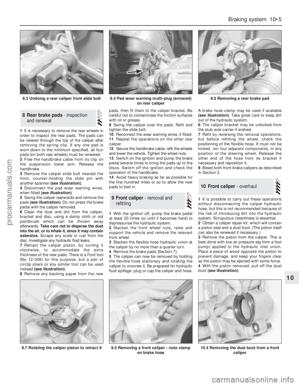
3Remove the caliper slide bolt nearest the
front, counter-holding the slide pin with
another spanner (see illustration).
4Disconnect the pad wear warning wires,
when fitted (see illustration).
5Swing the caliper rearwards and remove the
pads (see illustration). Do not press the brake
pedal with the caliper removed.
6Clean the dust and dirt from the caliper,
bracket and disc, using a damp cloth or old
paintbrush which can be thrown away
afterwards. Take care not to disperse the dust
into the air, or to inhale it, since it may contain
asbestos. Scrape any scale or rust from the
disc. Investigate any hydraulic fluid leaks.
7Retract the caliper piston, by turning it
clockwise, to accommodate the extra
thickness of the new pads. There is a Ford tool
(No 12-006) for this purpose, but a pair of
circlip pliers or any similar tool can be used
instead (see illustration).
8Remove any backing paper from the newpads, then fit them to the caliper bracket. Be
careful not to contaminate the friction surfaces
with oil or grease.
9Swing the caliper over the pads. Refit and
tighten the slide bolt.
10Reconnect the wear warning wires, if fitted.
11Repeat the operations on the other rear
caliper.
12Secure the handbrake cable, refit the wheels
and lower the vehicle. Tighten the wheel nuts.
13Switch on the ignition and pump the brake
pedal several times to bring the pads up to the
discs. Switch off the ignition and check the
operation of the handbrake.
14Avoid heavy braking as far as possible for
the first hundred miles or so to allow the new
pads to bed in.
1With the ignition off, pump the brake pedal
at least 20 times (or until it becomes hard) to
depressurise the hydraulic system.
2Slacken the front wheel nuts, raise and
support the vehicle and remove the relevant
front wheel.
3Slacken the flexible hose hydraulic union at
the caliper by no more than a quarter turn.
4Remove the brake pads (Section 7).
5The caliper can now be removed by holding
the flexible hose stationary and rotating the
caliper to unscrew it. Be prepared for hydraulic
fluid spillage: plug or cap the caliper and hose.A brake hose clamp may be used if available
(see illustration). Take great care to keep dirt
out of the hydraulic system.
6The caliper bracket may be unbolted from
the stub axle carrier if wished.
7Refit by reversing the removal operations,
but before refitting the wheel, check the
positioning of the flexible hose. It must not be
kinked, nor foul adjacent components, in any
position of the steering wheel. Release the
other end of the hose from its bracket if
necessary and reposition it.
8Bleed both front brake calipers as described
in Section 2.
1It is possible to carry out these operations
without disconnecting the caliper hydraulic
hose, but this is not recommended because of
the risk of introducing dirt into the hydraulic
system. Scrupulous cleanliness is essential.
2Obtain a caliper repair kit, which will contain
a piston seal and a dust boot. (The piston itself
can also be renewed if necessary.)
3Remove the piston from the caliper. This is
best done with low air pressure (eg from a foot
pump) applied to the hydraulic inlet union.
Place a piece of wood opposite the piston to
prevent damage, and keep your fingers clear
as the piston may be ejected with some force.
4With the piston removed, pull off the dust
boot (see illustration).
10Front caliper - overhaul
9Front caliper - removal and
refitting
8Rear brake pads - inspection
and renewal
Braking system 10•5
10
8.3 Undoing a rear caliper front slide bolt8.4 Pad wear warning multi-plug (arrowed)
on rear caliper8.5 Removing a rear brake pad
8.7 Rotating the caliper piston to retract it9.5 Removing a front caliper - note clamp
on brake hose10.4 Removing the dust boot from a front
caliper
procarmanuals.com
Page 154 of 255
15Bleed the brake hydraulic system and
adjust the handbrake on completion.
Models from 1987
16From 1987, the tab washer which secures
the guide plate centre bolt on each side has
been deleted. A self-locking bolt and plain
washer are used instead.
17The new bolt and washer should be fitted
to earlier models if the old bolt has been
removed for any reason. The tab washer
should be discarded.
18The tightening torque for the new bolt
remains the same as that given for the original.
1Remove the wheel trim. Apply the
handbrake and chock the front wheels.
2Slacken the driveshaft stub axle. This nut is
very tight. The left-hand nut has aleft-hand
thread, therefore it is undone clockwise.
3Remove the brake disc.
4Remove the driveshaft stub axle.
5Remove the four bolts which secure the
hub. Pull the hub off the driveshaft stub,
leaving the disc splash shield loose.
6Refit by reversing the removal operations.
Carry out the final tightening of the driveshaft
stub nut with the wheels on the ground.
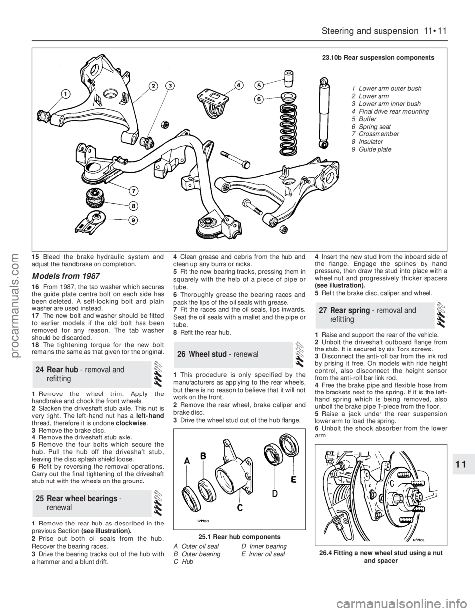
1Remove the rear hub as described in the
previous Section (see illustration).
2Prise out both oil seals from the hub.
Recover the bearing races.
3Drive the bearing tracks out of the hub with
a hammer and a blunt drift.4Clean grease and debris from the hub and
clean up any burrs or nicks.
5Fit the new bearing tracks, pressing them in
squarely with the help of a piece of pipe or
tube.
6Thoroughly grease the bearing races and
pack the lips of the oil seals with grease.
7Fit the races and the oil seals, lips inwards.
Seat the oil seals with a mallet and the pipe or
tube.
8Refit the rear hub.
1This procedure is only specified by the
manufacturers as applying to the rear wheels,
but there is no reason to believe that it will not
work on the front.
2Remove the rear wheel, brake caliper and
brake disc.
3Drive the wheel stud out of the hub flange. 4Insert the new stud from the inboard side of
the flange. Engage the splines by hand
pressure, then draw the stud into place with a
wheel nut and progressively thicker spacers
(see illustration).
5Refit the brake disc, caliper and wheel.
1Raise and support the rear of the vehicle.
2Unbolt the driveshaft outboard flange from
the stub. It is secured by six Torx screws.
3Disconnect the anti-roll bar from the link rod
by prising it free. On models with ride height
control, also disconnect the height sensor
from the anti-roll bar link rod.
4Free the brake pipe and flexible hose from
the brackets next to the spring. If it is the left-
hand spring which is being removed, also
unbolt the brake pipe T-piece from the floor.
5Raise a jack under the rear suspension
lower arm to load the spring.
6Unbolt the shock absorber from the lower
arm.
27Rear spring - removal and
refitting
26Wheel stud - renewal
25Rear wheel bearings -
renewal
24Rear hub - removal and
refitting
Steering and suspension 11•11
11
25.1 Rear hub components
A Outer oil seal
B Outer bearing
C HubD Inner bearing
E Inner oil seal26.4 Fitting a new wheel stud using a nut
and spacer
23.10b Rear suspension components
1 Lower arm outer bush
2 Lower arm
3 Lower arm inner bush
4 Final drive rear mounting
5 Buffer
6 Spring seat
7 Crossmember
8 Insulator
9 Guide plate
procarmanuals.com
Page 236 of 255
Introduction
A selection of good tools is a fundamental
requirement for anyone contemplating the
maintenance and repair of a motor vehicle. For
the owner who does not possess any, their
purchase will prove a considerable expense,
offsetting some of the savings made by doing-
it-yourself. However, provided that the tools
purchased meet the relevant national safety
standards and are of good quality, they will
last for many years and prove an extremely
worthwhile investment.
To help the average owner to decide which
tools are needed to carry out the various tasks
detailed in this manual, we have compiled
three lists of tools under the following
headings:
Maintenance and minor repair,
Repair and overhaul, and Special. Newcomers
to practical mechanics should start off with the
Maintenance and minor repairtool kit, and
confine themselves to the simpler jobs around
the vehicle. Then, as confidence and
experience grow, more difficult tasks can be
undertaken, with extra tools being purchased
as, and when, they are needed. In this way, a
Maintenance and minor repairtool kit can be
built up into a Repair and overhaultool kit over
a considerable period of time, without any
major cash outlays. The experienced do-it-
yourselfer will have a tool kit good enough for
most repair and overhaul procedures, and will
add tools from the Specialcategory when it is
felt that the expense is justified by the amount
of use to which these tools will be put.
Maintenance and minor repair tool
kit
The tools given in this list should be
considered as a minimum requirement if
routine maintenance, servicing and minor
repair operations are to be undertaken. We
recommend the purchase of combination
spanners (ring one end, open-ended the
other); although more expensive than open-
ended ones, they do give the advantages of
both types of spanner.
MCombination spanners:
Metric - 8, 9, 10, 11, 12, 13, 14, 15, 17 &
19 mmMAdjustable spanner - 35 mm jaw (approx)
MGearbox and final drive filler/level plug keys
MSpark plug spanner (with rubber insert)
MSpark plug gap adjustment tool
MSet of feeler blades
MBrake bleed nipple spanner
MScrewdrivers:
Flat blade - approx 100 mm long x 6 mm dia
Cross blade - approx 100 mm long x 6 mm
dia
MCombination pliers
MHacksaw (junior)
MTyre pump
MTyre pressure gauge
MOil can
MOil filter removal tool
MFine emery cloth
MWire brush (small)
MFunnel (medium size)
Repair and overhaul tool kit
These tools are virtually essential for anyone
undertaking any major repairs to a motor
vehicle, and are additional to those given in the
Maintenance and minor repairlist. Included in
this list is a comprehensive set of sockets.
Although these are expensive, they will be
found invaluable as they are so versatile -
particularly if various drives are included in the
set. We recommend the half-inch square-drive
type, as this can be used with most proprietary
torque wrenches. If you cannot afford a socket
set, even bought piecemeal, then inexpensive
tubular box spanners are a useful alternative.
The tools in this list will occasionally need to
be supplemented by tools from the Special
list:
MSockets (or box spanners) to cover range in
previous list (including Torx sockets)*
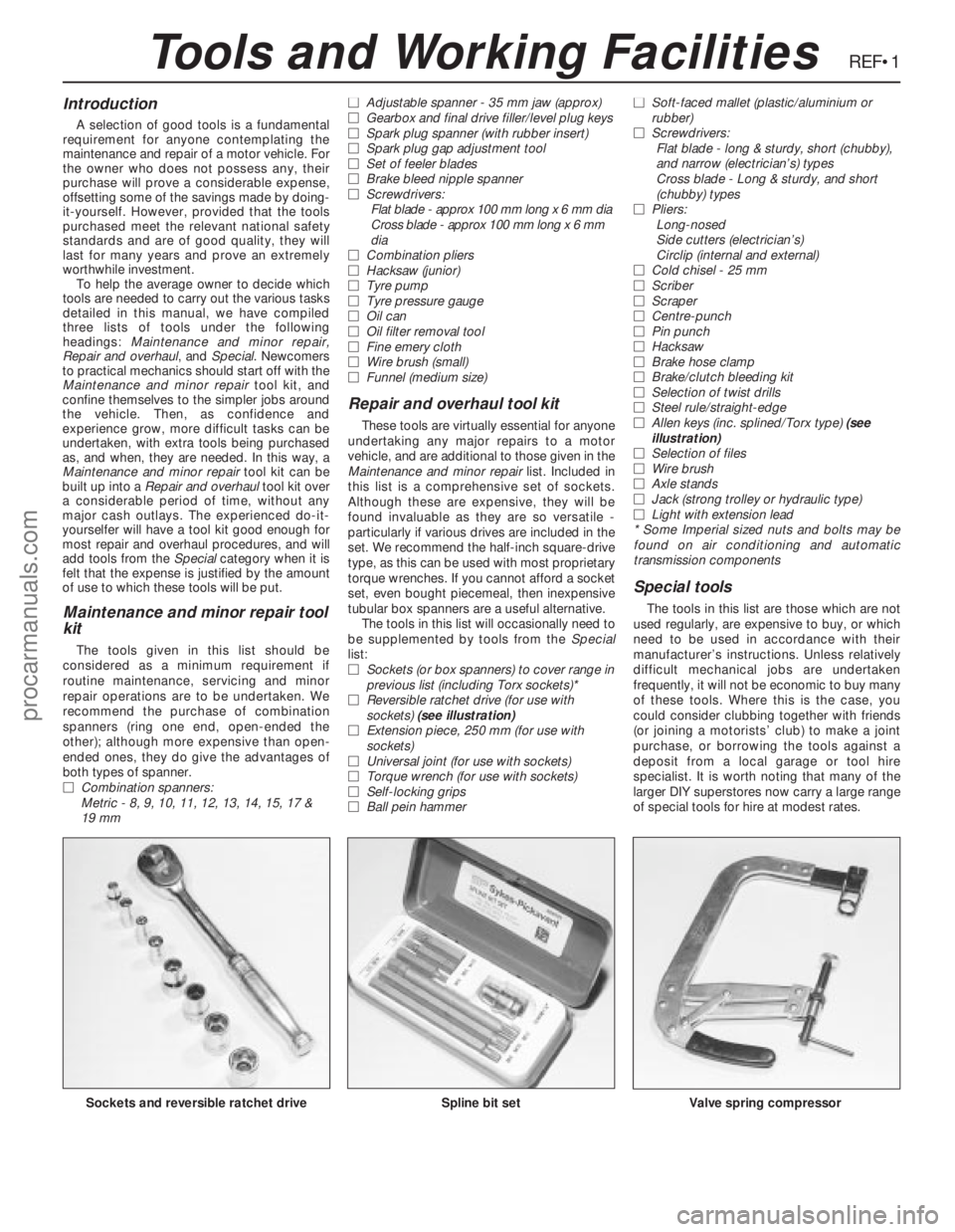
MReversible ratchet drive (for use with
sockets) (see illustration)
MExtension piece, 250 mm (for use with
sockets)
MUniversal joint (for use with sockets)
MTorque wrench (for use with sockets)
MSelf-locking grips
MBall pein hammerMSoft-faced mallet (plastic/aluminium or
rubber)
MScrewdrivers:
Flat blade - long & sturdy, short (chubby),
and narrow (electrician’s) types
Cross blade - Long & sturdy, and short
(chubby) types
MPliers:
Long-nosed
Side cutters (electrician’s)
Circlip (internal and external)
MCold chisel - 25 mm
MScriber
MScraper
MCentre-punch
MPin punch
MHacksaw
MBrake hose clamp
MBrake/clutch bleeding kit
MSelection of twist drills
MSteel rule/straight-edge
MAllen keys (inc. splined/Torx type) (see
illustration)
MSelection of files
MWire brush
MAxle stands
MJack (strong trolley or hydraulic type)
MLight with extension lead
* Some Imperial sized nuts and bolts may be
found on air conditioning and automatic
transmission components
Special tools
The tools in this list are those which are not
used regularly, are expensive to buy, or which
need to be used in accordance with their
manufacturer’s instructions. Unless relatively
difficult mechanical jobs are undertaken
frequently, it will not be economic to buy many
of these tools. Where this is the case, you
could consider clubbing together with friends
(or joining a motorists’ club) to make a joint
purchase, or borrowing the tools against a
deposit from a local garage or tool hire
specialist. It is worth noting that many of the
larger DIY superstores now carry a large range
of special tools for hire at modest rates.
REF•1
Spline bit setValve spring compressorSockets and reversible ratchet drive
Tools and Working Facilities
procarmanuals.com
Page 240 of 255
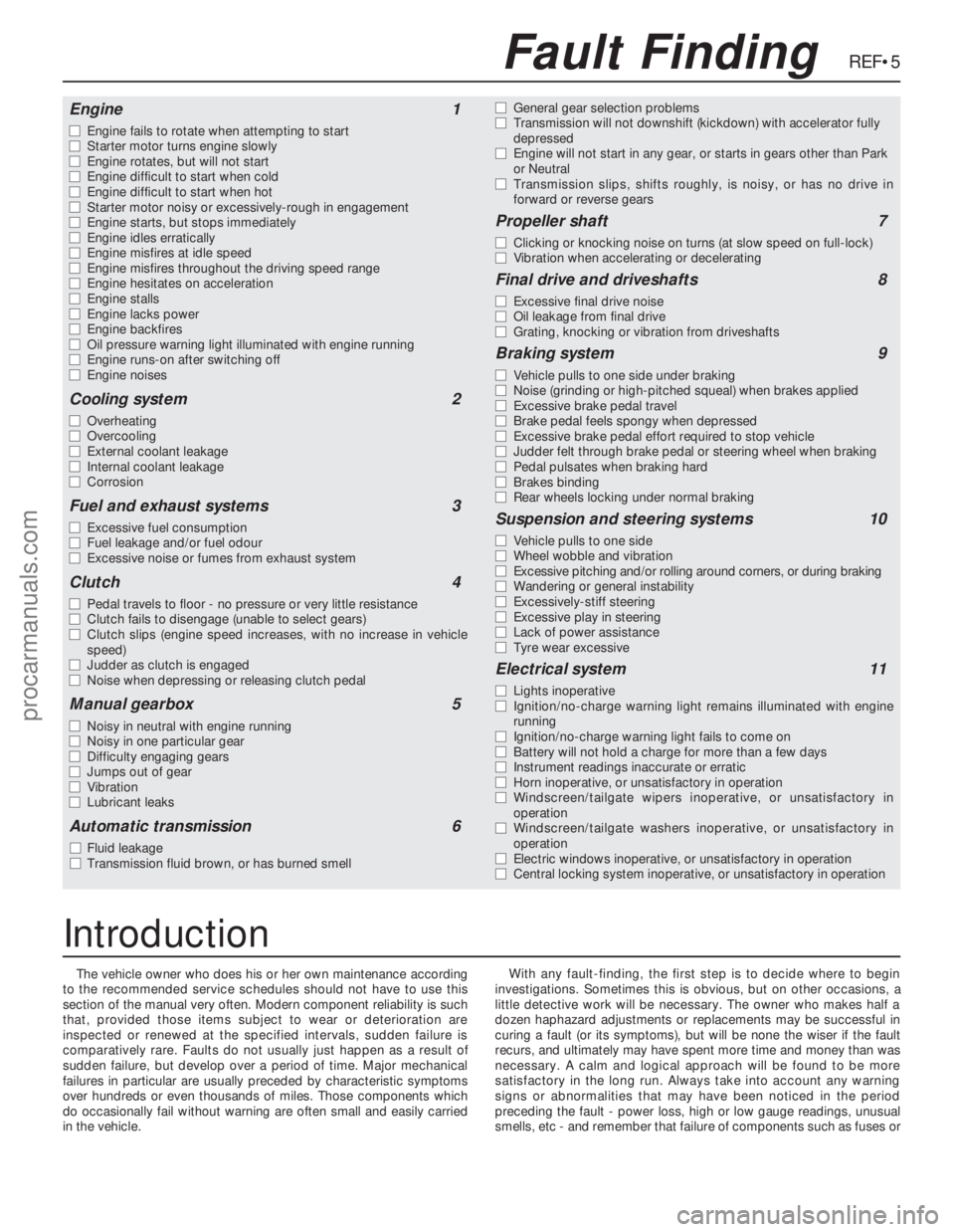
The vehicle owner who does his or her own maintenance according
to the recommended service schedules should not have to use this
section of the manual very often. Modern component reliability is such
that, provided those items subject to wear or deterioration are
inspected or renewed at the specified intervals, sudden failure is
comparatively rare. Faults do not usually just happen as a result of
sudden failure, but develop over a period of time. Major mechanical
failures in particular are usually preceded by characteristic symptoms
over hundreds or even thousands of miles. Those components which
do occasionally fail without warning are often small and easily carried
in the vehicle.With any fault-finding, the first step is to decide where to begin
investigations. Sometimes this is obvious, but on other occasions, a
little detective work will be necessary. The owner who makes half a
dozen haphazard adjustments or replacements may be successful in
curing a fault (or its symptoms), but will be none the wiser if the fault
recurs, and ultimately may have spent more time and money than was
necessary. A calm and logical approach will be found to be more
satisfactory in the long run. Always take into account any warning
signs or abnormalities that may have been noticed in the period
preceding the fault - power loss, high or low gauge readings, unusual
smells, etc - and remember that failure of components such as fuses or
REF•5Fault Finding
Engine1
m mEngine fails to rotate when attempting to start
m mStarter motor turns engine slowly
m mEngine rotates, but will not start
m mEngine difficult to start when cold
m mEngine difficult to start when hot
m mStarter motor noisy or excessively-rough in engagement
m mEngine starts, but stops immediately
m mEngine idles erratically
m mEngine misfires at idle speed
m mEngine misfires throughout the driving speed range
m mEngine hesitates on acceleration
m mEngine stalls
m mEngine lacks power
m mEngine backfires
m mOil pressure warning light illuminated with engine running
m mEngine runs-on after switching off
m mEngine noises
Cooling system2
m
mOverheating
m mOvercooling
m mExternal coolant leakage
m mInternal coolant leakage
m mCorrosion
Fuel and exhaust systems3
m
mExcessive fuel consumption
m mFuel leakage and/or fuel odour
m mExcessive noise or fumes from exhaust system
Clutch4
m
mPedal travels to floor - no pressure or very little resistance
m mClutch fails to disengage (unable to select gears)
m mClutch slips (engine speed increases, with no increase in vehicle
speed)
m mJudder as clutch is engaged
m mNoise when depressing or releasing clutch pedal
Manual gearbox5
m
mNoisy in neutral with engine running
m mNoisy in one particular gear
m mDifficulty engaging gears
m mJumps out of gear
m mVibration
m mLubricant leaks
Automatic transmission6
m
mFluid leakage
m mTransmission fluid brown, or has burned smellm mGeneral gear selection problems
m mTransmission will not downshift (kickdown) with accelerator fully
depressed
m mEngine will not start in any gear, or starts in gears other than Park
or Neutral
m mTransmission slips, shifts roughly, is noisy, or has no drive in
forward or reverse gears
Propeller shaft7
m
mClicking or knocking noise on turns (at slow speed on full-lock)
m mVibration when accelerating or decelerating
Final drive and driveshafts8
m
mExcessive final drive noise
m mOil leakage from final drive
m mGrating, knocking or vibration from driveshafts
Braking system9
m
mVehicle pulls to one side under braking
m mNoise (grinding or high-pitched squeal) when brakes applied
m mExcessive brake pedal travel
m mBrake pedal feels spongy when depressed
m mExcessive brake pedal effort required to stop vehicle
m mJudder felt through brake pedal or steering wheel when braking
m mPedal pulsates when braking hard
m mBrakes binding
m mRear wheels locking under normal braking
Suspension and steering systems10
m
mVehicle pulls to one side
m mWheel wobble and vibration
m mExcessive pitching and/or rolling around corners, or during braking
m mWandering or general instability
m mExcessively-stiff steering
m mExcessive play in steering
m mLack of power assistance
m mTyre wear excessive
Electrical system11
m
mLights inoperative
m mIgnition/no-charge warning light remains illuminated with engine
running
m mIgnition/no-charge warning light fails to come on
m mBattery will not hold a charge for more than a few days
m mInstrument readings inaccurate or erratic
m mHorn inoperative, or unsatisfactory in operation
m mWindscreen/tailgate wipers inoperative, or unsatisfactory in
operation
m mWindscreen/tailgate washers inoperative, or unsatisfactory in
operation
m mElectric windows inoperative, or unsatisfactory in operation
m mCentral locking system inoperative, or unsatisfactory in operation
Introduction
procarmanuals.com
Page 242 of 255
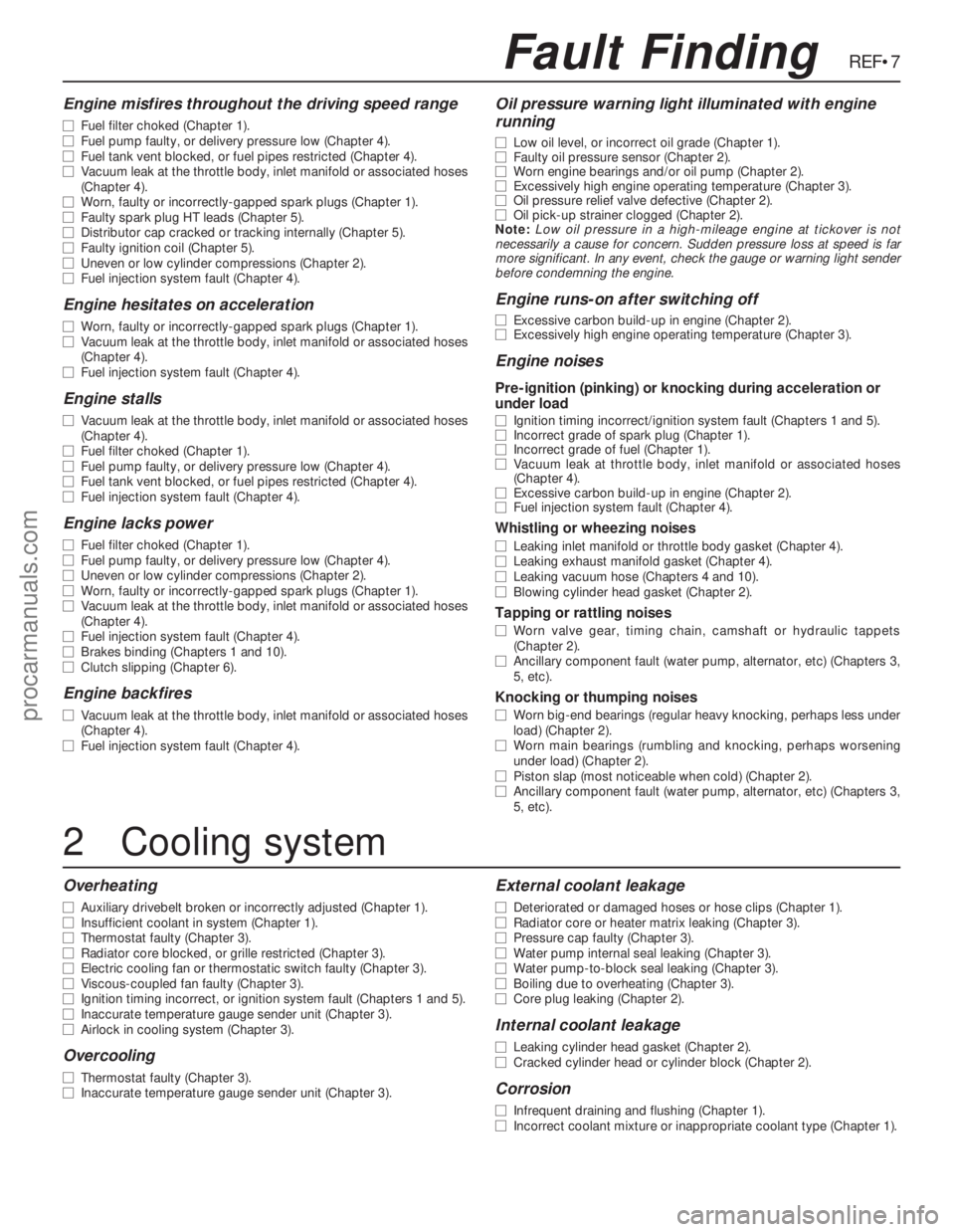
Engine misfires throughout the driving speed range
m mFuel filter choked (Chapter 1).
m mFuel pump faulty, or delivery pressure low (Chapter 4).
m mFuel tank vent blocked, or fuel pipes restricted (Chapter 4).
m mVacuum leak at the throttle body, inlet manifold or associated hoses
(Chapter 4).
m mWorn, faulty or incorrectly-gapped spark plugs (Chapter 1).
m mFaulty spark plug HT leads (Chapter 5).
m mDistributor cap cracked or tracking internally (Chapter 5).
m mFaulty ignition coil (Chapter 5).
m mUneven or low cylinder compressions (Chapter 2).
m mFuel injection system fault (Chapter 4).
Engine hesitates on acceleration
m
mWorn, faulty or incorrectly-gapped spark plugs (Chapter 1).
m mVacuum leak at the throttle body, inlet manifold or associated hoses
(Chapter 4).
m mFuel injection system fault (Chapter 4).
Engine stalls
m
mVacuum leak at the throttle body, inlet manifold or associated hoses
(Chapter 4).
m mFuel filter choked (Chapter 1).
m mFuel pump faulty, or delivery pressure low (Chapter 4).
m mFuel tank vent blocked, or fuel pipes restricted (Chapter 4).
m mFuel injection system fault (Chapter 4).
Engine lacks power
m
mFuel filter choked (Chapter 1).
m mFuel pump faulty, or delivery pressure low (Chapter 4).
m mUneven or low cylinder compressions (Chapter 2).
m mWorn, faulty or incorrectly-gapped spark plugs (Chapter 1).
m mVacuum leak at the throttle body, inlet manifold or associated hoses
(Chapter 4).
m mFuel injection system fault (Chapter 4).
m mBrakes binding (Chapters 1 and 10).
m mClutch slipping (Chapter 6).
Engine backfires
m
mVacuum leak at the throttle body, inlet manifold or associated hoses
(Chapter 4).
m mFuel injection system fault (Chapter 4).
Oil pressure warning light illuminated with engine
running
m mLow oil level, or incorrect oil grade (Chapter 1).
m mFaulty oil pressure sensor (Chapter 2).
m mWorn engine bearings and/or oil pump (Chapter 2).
m mExcessively high engine operating temperature (Chapter 3).
m mOil pressure relief valve defective (Chapter 2).
m mOil pick-up strainer clogged (Chapter 2).
Note:Low oil pressure in a high-mileage engine at tickover is not
necessarily a cause for concern. Sudden pressure loss at speed is far
more significant. In any event, check the gauge or warning light sender
before condemning the engine.
Engine runs-on after switching off
m mExcessive carbon build-up in engine (Chapter 2).
m mExcessively high engine operating temperature (Chapter 3).
Engine noises
Pre-ignition (pinking) or knocking during acceleration or
under load
m mIgnition timing incorrect/ignition system fault (Chapters 1 and 5).
m mIncorrect grade of spark plug (Chapter 1).
m mIncorrect grade of fuel (Chapter 1).
m mVacuum leak at throttle body, inlet manifold or associated hoses
(Chapter 4).
m mExcessive carbon build-up in engine (Chapter 2).
m mFuel injection system fault (Chapter 4).
Whistling or wheezing noises
m
mLeaking inlet manifold or throttle body gasket (Chapter 4).
m mLeaking exhaust manifold gasket (Chapter 4).
m mLeaking vacuum hose (Chapters 4 and 10).
m mBlowing cylinder head gasket (Chapter 2).
Tapping or rattling noises
m
mWorn valve gear, timing chain, camshaft or hydraulic tappets
(Chapter 2).
m mAncillary component fault (water pump, alternator, etc) (Chapters 3,
5, etc).
Knocking or thumping noises
m mWorn big-end bearings (regular heavy knocking, perhaps less under
load) (Chapter 2).
m mWorn main bearings (rumbling and knocking, perhaps worsening
under load) (Chapter 2).
m mPiston slap (most noticeable when cold) (Chapter 2).
m mAncillary component fault (water pump, alternator, etc) (Chapters 3,
5, etc).
REF•7Fault Finding
2Cooling system
Overheating
m
mAuxiliary drivebelt broken or incorrectly adjusted (Chapter 1).
m mInsufficient coolant in system (Chapter 1).
m mThermostat faulty (Chapter 3).
m mRadiator core blocked, or grille restricted (Chapter 3).
m mElectric cooling fan or thermostatic switch faulty (Chapter 3).
m mViscous-coupled fan faulty (Chapter 3).
m mIgnition timing incorrect, or ignition system fault (Chapters 1 and 5).
m mInaccurate temperature gauge sender unit (Chapter 3).
m mAirlock in cooling system (Chapter 3).
Overcooling
m
mThermostat faulty (Chapter 3).
m mInaccurate temperature gauge sender unit (Chapter 3).
External coolant leakage
m
mDeteriorated or damaged hoses or hose clips (Chapter 1).
m mRadiator core or heater matrix leaking (Chapter 3).
m mPressure cap faulty (Chapter 3).
m mWater pump internal seal leaking (Chapter 3).
m mWater pump-to-block seal leaking (Chapter 3).
m mBoiling due to overheating (Chapter 3).
m mCore plug leaking (Chapter 2).
Internal coolant leakage
m
mLeaking cylinder head gasket (Chapter 2).
m mCracked cylinder head or cylinder block (Chapter 2).
Corrosion
m
mInfrequent draining and flushing (Chapter 1).
m mIncorrect coolant mixture or inappropriate coolant type (Chapter 1).
procarmanuals.com
Page 243 of 255
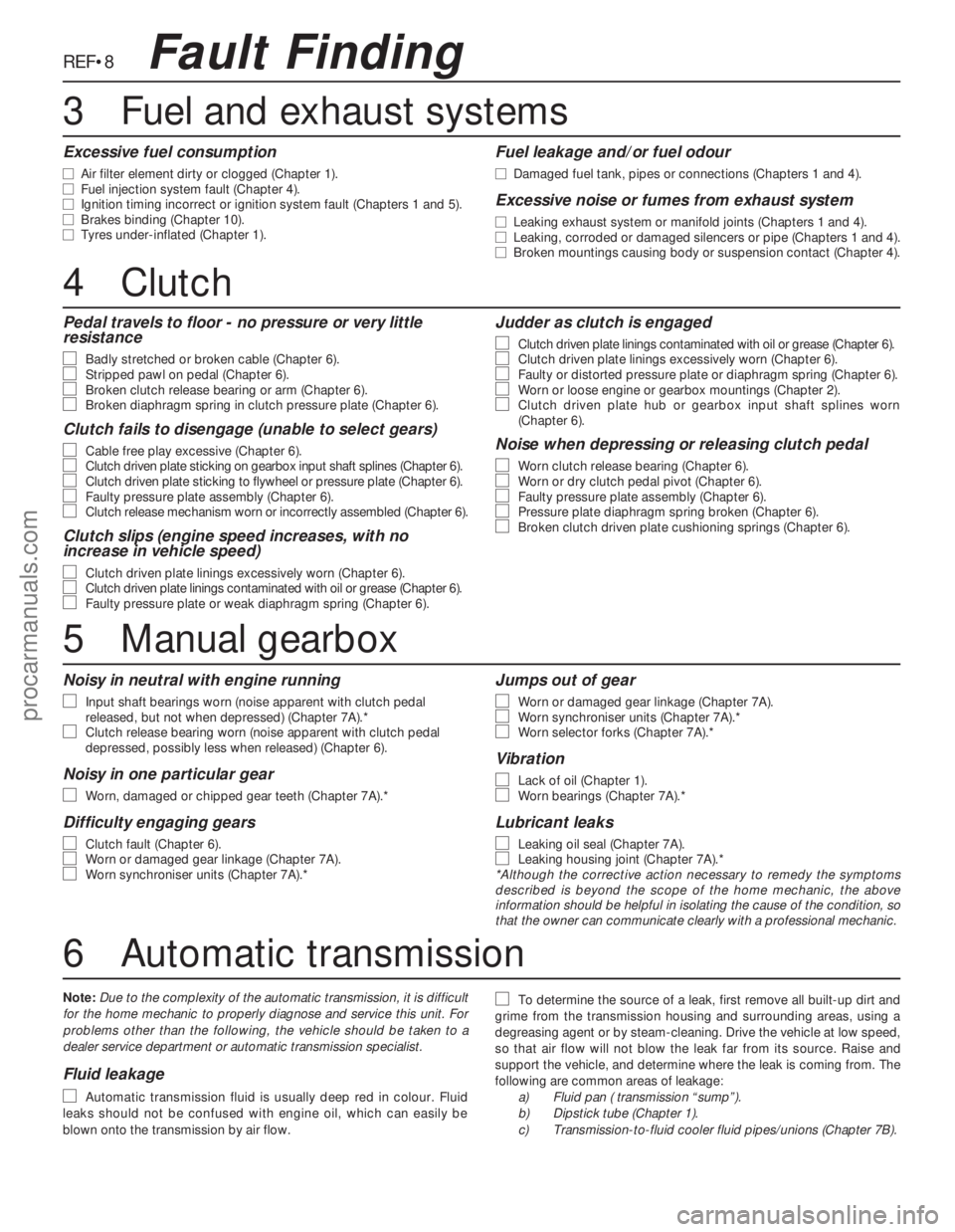
REF•8
Pedal travels to floor - no pressure or very little
resistance
m m
Badly stretched or broken cable (Chapter 6).m
mStripped pawl on pedal (Chapter 6).m
mBroken clutch release bearing or arm (Chapter 6).m
mBroken diaphragm spring in clutch pressure plate (Chapter 6).
Clutch fails to disengage (unable to select gears)
m m
Cable free play excessive (Chapter 6).m
mClutch driven plate sticking on gearbox input shaft splines (Chapter 6).m
mClutch driven plate sticking to flywheel or pressure plate (Chapter 6).m
mFaulty pressure plate assembly (Chapter 6).m
mClutch release mechanism worn or incorrectly assembled (Chapter 6).
Clutch slips (engine speed increases, with no
increase in vehicle speed)
m m
Clutch driven plate linings excessively worn (Chapter 6).m
mClutch driven plate linings contaminated with oil or grease (Chapter 6).m
mFaulty pressure plate or weak diaphragm spring (Chapter 6).
Judder as clutch is engaged
m m
Clutch driven plate linings contaminated with oil or grease (Chapter 6).m
mClutch driven plate linings excessively worn (Chapter 6).m
mFaulty or distorted pressure plate or diaphragm spring (Chapter 6).m
mWorn or loose engine or gearbox mountings (Chapter 2).m
mClutch driven plate hub or gearbox input shaft splines worn
(Chapter 6).
Noise when depressing or releasing clutch pedal
m m
Worn clutch release bearing (Chapter 6).m
mWorn or dry clutch pedal pivot (Chapter 6).m
mFaulty pressure plate assembly (Chapter 6).m
mPressure plate diaphragm spring broken (Chapter 6).m
mBroken clutch driven plate cushioning springs (Chapter 6).
Excessive fuel consumption
m
mAir filter element dirty or clogged (Chapter 1).
m mFuel injection system fault (Chapter 4).
m mIgnition timing incorrect or ignition system fault (Chapters 1 and 5).
m mBrakes binding (Chapter 10).
m mTyres under-inflated (Chapter 1).
Fuel leakage and/or fuel odour
m
mDamaged fuel tank, pipes or connections (Chapters 1 and 4).
Excessive noise or fumes from exhaust system
m
mLeaking exhaust system or manifold joints (Chapters 1 and 4).
m mLeaking, corroded or damaged silencers or pipe (Chapters 1 and 4).
m mBroken mountings causing body or suspension contact (Chapter 4).
Fault Finding
4Clutch
5Manual gearbox
Noisy in neutral with engine running
m m
Input shaft bearings worn (noise apparent with clutch pedal
released, but not when depressed) (Chapter 7A).*
m mClutch release bearing worn (noise apparent with clutch pedal
depressed, possibly less when released) (Chapter 6).
Noisy in one particular gear
m m
Worn, damaged or chipped gear teeth (Chapter 7A).*
Difficulty engaging gears
m m
Clutch fault (Chapter 6).m
mWorn or damaged gear linkage (Chapter 7A).m
mWorn synchroniser units (Chapter 7A).*
Jumps out of gear
m m
Worn or damaged gear linkage (Chapter 7A).m
mWorn synchroniser units (Chapter 7A).*m
mWorn selector forks (Chapter 7A).*
Vibration
m m
Lack of oil (Chapter 1).m
mWorn bearings (Chapter 7A).*
Lubricant leaks
m m
Leaking oil seal (Chapter 7A).m
mLeaking housing joint (Chapter 7A).*
*Although the corrective action necessary to remedy the symptoms
described is beyond the scope of the home mechanic, the above
information should be helpful in isolating the cause of the condition, so
that the owner can communicate clearly with a professional mechanic.
6Automatic transmission
Note:Due to the complexity of the automatic transmission, it is difficult
for the home mechanic to properly diagnose and service this unit. For
problems other than the following, the vehicle should be taken to a
dealer service department or automatic transmission specialist.
Fluid leakage
m m
Automatic transmission fluid is usually deep red in colour. Fluid
leaks should not be confused with engine oil, which can easily be
blown onto the transmission by air flow.
m mTo determine the source of a leak, first remove all built-up dirt and
grime from the transmission housing and surrounding areas, using a
degreasing agent or by steam-cleaning. Drive the vehicle at low speed,
so that air flow will not blow the leak far from its source. Raise and
support the vehicle, and determine where the leak is coming from. The
following are common areas of leakage:
a)Fluid pan ( transmission “sump”).
b)Dipstick tube (Chapter 1).
c)Transmission-to-fluid cooler fluid pipes/unions (Chapter 7B).
3Fuel and exhaust systems
procarmanuals.com
Page 245 of 255
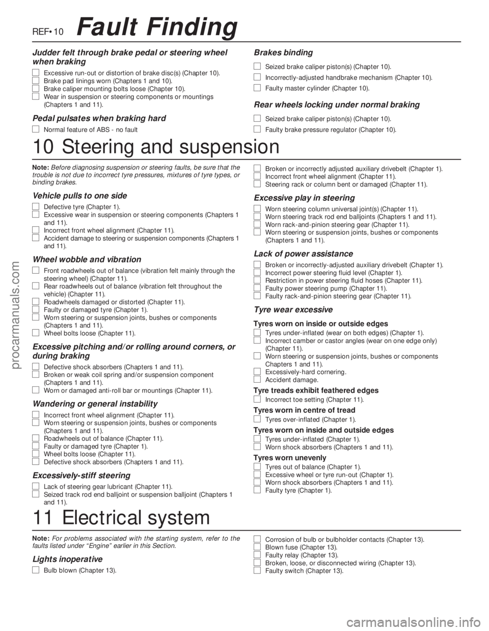
Note:For problems associated with the starting system, refer to the
faults listed under “Engine” earlier in this Section.
Lights inoperative
m m
Bulb blown (Chapter 13).
m
mCorrosion of bulb or bulbholder contacts (Chapter 13).m
mBlown fuse (Chapter 13).m
mFaulty relay (Chapter 13).m
mBroken, loose, or disconnected wiring (Chapter 13).m
mFaulty switch (Chapter 13).
REF•10Fault Finding
Judder felt through brake pedal or steering wheel
when braking
m m
Excessive run-out or distortion of brake disc(s) (Chapter 10).m
mBrake pad linings worn (Chapters 1 and 10).m
mBrake caliper mounting bolts loose (Chapter 10).m
mWear in suspension or steering components or mountings
(Chapters 1 and 11).
Pedal pulsates when braking hard
m m
Normal feature of ABS - no fault
Brakes binding
m m
Seized brake caliper piston(s) (Chapter 10).
m
mIncorrectly-adjusted handbrake mechanism (Chapter 10).
m
mFaulty master cylinder (Chapter 10).
Rear wheels locking under normal braking
m m
Seized brake caliper piston(s) (Chapter 10).
m
mFaulty brake pressure regulator (Chapter 10).
10Steering and suspension
Note:Before diagnosing suspension or steering faults, be sure that the
trouble is not due to incorrect tyre pressures, mixtures of tyre types, or
binding brakes.
Vehicle pulls to one side
m m
Defective tyre (Chapter 1).m
mExcessive wear in suspension or steering components (Chapters 1
and 11).
m mIncorrect front wheel alignment (Chapter 11).m
mAccident damage to steering or suspension components (Chapters 1
and 11).
Wheel wobble and vibration
m m
Front roadwheels out of balance (vibration felt mainly through the
steering wheel) (Chapter 11).
m mRear roadwheels out of balance (vibration felt throughout the
vehicle) (Chapter 11).
m mRoadwheels damaged or distorted (Chapter 11).m
mFaulty or damaged tyre (Chapter 1).m
mWorn steering or suspension joints, bushes or components
(Chapters 1 and 11).
m mWheel bolts loose (Chapter 11).
Excessive pitching and/or rolling around corners, or
during braking
m m
Defective shock absorbers (Chapters 1 and 11).m
mBroken or weak coil spring and/or suspension component
(Chapters 1 and 11).
m mWorn or damaged anti-roll bar or mountings (Chapter 11).
Wandering or general instability
m m
Incorrect front wheel alignment (Chapter 11).m
mWorn steering or suspension joints, bushes or components
(Chapters 1 and 11).
m mRoadwheels out of balance (Chapter 11).m
mFaulty or damaged tyre (Chapter 1).m
mWheel bolts loose (Chapter 11).m
mDefective shock absorbers (Chapters 1 and 11).
Excessively-stiff steering
m m
Lack of steering gear lubricant (Chapter 11).m
mSeized track rod end balljoint or suspension balljoint (Chapters 1
and 11).
m mBroken or incorrectly adjusted auxiliary drivebelt (Chapter 1).m
mIncorrect front wheel alignment (Chapter 11).m
mSteering rack or column bent or damaged (Chapter 11).
Excessive play in steering
m m
Worn steering column universal joint(s) (Chapter 11).m
mWorn steering track rod end balljoints (Chapters 1 and 11).m
mWorn rack-and-pinion steering gear (Chapter 11).m
mWorn steering or suspension joints, bushes or components
(Chapters 1 and 11).
Lack of power assistance
m m
Broken or incorrectly-adjusted auxiliary drivebelt (Chapter 1).m
mIncorrect power steering fluid level (Chapter 1).m
mRestriction in power steering fluid hoses (Chapter 11).m
mFaulty power steering pump (Chapter 11).m
mFaulty rack-and-pinion steering gear (Chapter 11).
Tyre wear excessive
Tyres worn on inside or outside edges
m
mTyres under-inflated (wear on both edges) (Chapter 1).m
mIncorrect camber or castor angles (wear on one edge only)
(Chapter 11).
m mWorn steering or suspension joints, bushes or components
Chapters 1 and 11).
m mExcessively-hard cornering.m
mAccident damage.
Tyre treads exhibit feathered edges
m
mIncorrect toe setting (Chapter 11).
Tyres worn in centre of tread
m
mTyres over-inflated (Chapter 1).
Tyres worn on inside and outside edges
m
mTyres under-inflated (Chapter 1).m
mWorn shock absorbers (Chapters 1 and 11).
Tyres worn unevenly
m
mTyres out of balance (Chapter 1).m
mExcessive wheel or tyre run-out (Chapter 1).m
mWorn shock absorbers (Chapters 1 and 11).m
mFaulty tyre (Chapter 1).
11Electrical system
procarmanuals.com