1985 FORD GRANADA alternator belt
[x] Cancel search: alternator beltPage 85 of 255
Cooling system
The cooling system is of pressurised type
and includes a front mounted crossflow
radiator, belt-driven water pump, temperature-
sensitive thermo-viscous fan (on DOHC
models, an electrically-operated cooling fan is
fitted, operated by a switch in the thermostat
housing), wax type thermostat, and an
expansion and degas tank.
The radiator matrix is of copper and brass
construction and the end tanks are of plastic.
On automatic transmission models the right-
hand side end tank incorporates the
transmission oil cooler.
The thermostat is located behind the water
outlet elbow at the front of the cylinder head
on OHCmodels, and on the front of the water
pump on V6 models. Its purpose is to ensure
rapid engine warm-up by restricting the flow of
coolant in the engine when cold, and also to
assist in regulating the normal operating
temperature of the engine.
The expansion tank incorporates a pressure
cap which effectively pressurises the cooling
system as the coolant temperature rises,
thereby increasing the boiling point of the
coolant. The tank also has a further degas
function. Any accumulation of air bubbles in
the coolant, in particular in the thermostat
housing and the radiator, is returned to the
tank and released in the air space thus
maintaining the efficiency of the coolant.
On models fitted with the auxiliary warning
system, the expansion tank contains a level
sensor which operates a warning light if the
coolant level falls significantly.
When the engine is started from cold, the
water pump circulates coolant around the
cylinder block, cylinder head(s) and inlet
manifold. The warm coolant passes through
the automatic choke housing (when
applicable) and through the heater matrix
before returning to the engine. As the coolant
expands, the level in the expansion tank rises.
Circulation of coolant through the radiator is
prevented while the thermostat is shut. When
the coolant reaches the predeterminedtemperature the thermostat opens and hot
water passes through the top hose to the top
of the radiator. As the water circulates down
through the radiator, it is cooled by the
passage of air past the radiator when the car is
in forward motion, supplemented by the action
of the thermo-viscous fan when necessary.
Having reached the bottom of the radiator, the
water is now cool and the cycle is repeated.
Circulation of water continues through the
expansion tank, inlet manifold and heater at all
times; the heater temperature control being by
an air flap.
The thermo-viscous fan is controlled by the
temperature of air behind the radiator. When
the air temperature reaches a predetermined
level, a bi-metallic coil commences to open a
valve within the unit and silicon fluid is fed
through a system of vanes. Half of the vanes
are driven directly by the water pump and the
remaining half are connected to the fan blades.
The vanes are arranged so that drive is
transmitted to the fan blades in relation to the
drag or viscosity of the fluid, and this in turn
depends on ambient temperature and engine
speed. The fan is therefore only operated when
required, and compared with direct drive type
fan represents a considerable improvement in
fuel economy, drivebelt wear and fan noise.
Air conditioning
Air conditioning is fitted as standard on
Scorpio models and is optionally available on
some other models. In conjunction with the
heater, the system enables any reasonable air
temperature to be achieved inside the car, it
also reduces the humidity of the incoming air,
aiding demisting even when cooling is not
required.
The refrigeration side of the air conditioning
system functions in a similar way to a
domestic refrigerator. A compressor, belt-
driven from the crankshaft pulley, draws
refrigerant in its gaseous phase from an
evaporator. The compressed refrigerant
passes through a condenser where it loses
heat and enters its liquid phase. After
dehydration the refrigerant returns to the
evaporator where it absorbs heat from air
passing over the evaporator fins. The
refrigerant becomes a gas again and the cycle
is repeated.Various subsidiary controls and sensors
protect the system against excessive
temperature and pressures. Additionally,
engine idle speed is increased when the
system is in use to compensate for the
additional load imposed by the compressor.
Precautions
Antifreeze mixture
Antifreeze mixture is poisonous. Keep it out
of reach of children and pets. Wash splashes
off skin and clothing with plenty of water.
Wash splashes off vehicle paintwork to avoid
discolouration.
Antifreeze/water mixture must be renewed
every two years to preserve its anti-corrosive
properties. In climates where antifreeze
protection is unnecessary, a corrosion
inhibitor may be used instead - consult a Ford
dealer. Never run the engine for long periods
with plain water as coolant. Only use the
specified antifreeze, as inferior brands may not
contain the necessary corrosion inhibitors, or
may break down at high temperatures.
Antifreeze containing methanol is particularly
to be avoided, as the methanol evaporates.
The specified mixture is 45 to 50%
antifreeze and 50 to 55% clean soft water (by
volume). Mix the required quantity in a clean
container.
Air conditioning refrigerant
Although the refrigerant is not itself toxic, in
the presence of a naked flame (or a lighted
cigarette) it forms a highly toxic gas. Liquid
refrigerant spilled on the skin will cause
frostbite. If refrigerant enters the eyes, rinse
them with a dilute solution of boric acid and
seek medical advice immediately.
In view of the above points, and of the need
for specialised equipment for evacuating and
recharging the system, any work which
requires the disconnection of a refrigerant line
must be left to a specialist.
Do not allow refrigerant lines to be exposed
to temperatures above 110°C (230°F) - eg
during welding or paint drying operations and
do not operate the air conditioning system if it
is known to be short of refrigerant, or further
damage may result.
1General information and
precautions
3•2Cooling, heating and ventilation systems
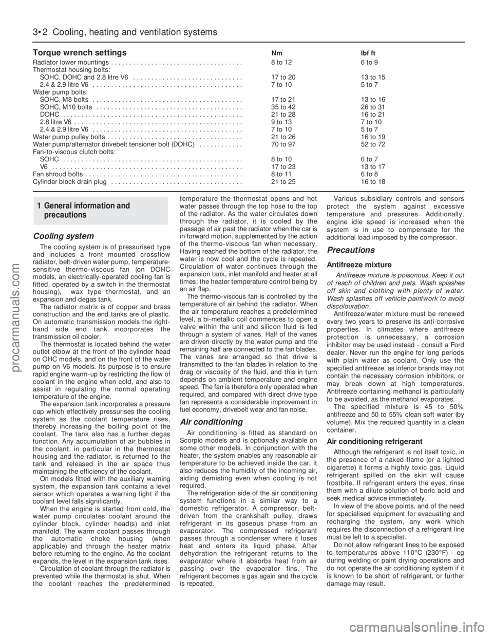
Torque wrench settingsNmlbf ft
Radiator lower mountings . . . . . . . . . . . . . . . . . . . . . . . . . . . . . . . . . . . .8 to 126 to 9
Thermostat housing bolts:
SOHC, DOHC and 2.8 litre V6 . . . . . . . . . . . . . . . . . . . . . . . . . . . . . .17 to 2013 to 15
2.4 & 2.9 litre V6 . . . . . . . . . . . . . . . . . . . . . . . . . . . . . . . . . . . . . . . . .7 to 105 to 7
Water pump bolts:
SOHC, M8 bolts . . . . . . . . . . . . . . . . . . . . . . . . . . . . . . . . . . . . . . . . .17 to 2113 to 16
SOHC, M10 bolts . . . . . . . . . . . . . . . . . . . . . . . . . . . . . . . . . . . . . . . .35 to 4226 to 31
DOHC . . . . . . . . . . . . . . . . . . . . . . . . . . . . . . . . . . . . . . . . . . . . . . . . .21 to 2816 to 21
2.8 litre V6 . . . . . . . . . . . . . . . . . . . . . . . . . . . . . . . . . . . . . . . . . . . . . .9 to 137 to 10
2.4 & 2.9 litre V6 . . . . . . . . . . . . . . . . . . . . . . . . . . . . . . . . . . . . . . . . .7 to 105 to 7
Water pump pulley bolts . . . . . . . . . . . . . . . . . . . . . . . . . . . . . . . . . . . . .21 to 2616 to 19
Water pump/alternator drivebelt tensioner bolt (DOHC) . . . . . . . . . . . .70 to 9752 to 72
Fan-to-viscous clutch bolts:
SOHC . . . . . . . . . . . . . . . . . . . . . . . . . . . . . . . . . . . . . . . . . . . . . . . . .8 to 106 to 7
V6 . . . . . . . . . . . . . . . . . . . . . . . . . . . . . . . . . . . . . . . . . . . . . . . . . . . .17 to 2313 to 17
Fan shroud bolts . . . . . . . . . . . . . . . . . . . . . . . . . . . . . . . . . . . . . . . . . . .8 to 116 to 8
Cylinder block drain plug . . . . . . . . . . . . . . . . . . . . . . . . . . . . . . . . . . . .21 to 2516 to 18
procarmanuals.com
Page 89 of 255
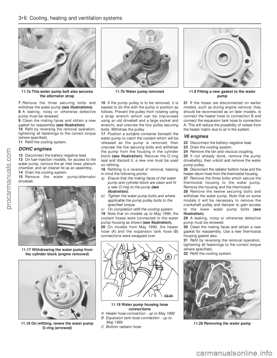
7Remove the three securing bolts and
withdraw the water pump (see illustrations).
8A leaking, noisy or otherwise defective
pump must be renewed.
9Clean the mating faces and obtain a new
gasket for reassembly (see illustration).
10Refit by reversing the removal operation,
tightening all fastenings to the correct torque
(where specified).
11Refill the cooling system.
DOHC engines
12Disconnect the battery negative lead.
13On fuel-injection models, for access to the
water pump, remove the air inlet hose, plenum
chamber, and air cleaner lid as an assembly.
14Drain the cooling system.
15Remove the water pump/alternator
drivebelt.16If the pump pulley is to be removed, it is
easiest to do this with the pump in position as
follows. Prevent the pulley from rotating using
a strap wrench (which can be improvised
using an old drivebelt and a large socket and
wrench), and unscrew the four pulley securing
bolts. Withdraw the pulley.
17Position a suitable container beneath the
water pump to catch the coolant which will be
released as the pump is removed, then
unscrew the five securing bolts and withdraw
the pump from the housing in the cylinder
block (see illustration). Recover the O-ring
seal and discard it; a new one must be used
on refitting.
18Refitting is a reversal of removal, bearing
in mind the following points:
a)Ensure that the mating faces of the water
pump and cylinder block are clean and fit
a new O-ring to the pump (see
illustration).
b)Tighten the water pump bolts and where
applicable the pump pulley bolts to the
specified torque.
c)On completion refill the cooling system.
19Note that on models up to May 1990, the
coolant hoses were connected to the water
pump housing as shown(see illustration).
20On models from May 1990, the heater
hose (A) and the expansion tank hose (B)
connections were swapped over.21If the hoses are disconnected on earlier
models, such as during engine removal, they
should be reconnected as on later models, ie
connect the heater hose to connection B and
connect the expansion tank hose to connection
A. This will reduce the possibility of noises from
the heater matrix due to air in the system.
V6 engines
22Disconnect the battery negative lead.
23Drain the cooling system.
24Remove the fan and viscous coupling.
25If not already done, remove the pump
drivebelt(s), then unbolt and remove the water
pump pulley.
26Disconnect the radiator bottom hose and the
heater return hose from the thermostat housing.
27Remove the three bolts which secure the
thermostat housing to the water pump.
Remove the housing and the thermostat.
28Remove the twelve securing bolts and
withdraw the water pump. Note that on some
models it will be necessary to remove the
crankshaft pulley and damper to gain access
to the lower water pump bolts (see
illustration).
29A leaking, noisy or otherwise defective
pump must be renewed.
30Clean the mating faces and obtain a new
gasket for reassembly. Use a new thermostat
housing gasket also.
31Refit by reversing the removal operation,
tightening all fastenings to the correct torque
(where specified).
32Refill the cooling system.
3•6Cooling, heating and ventilation systems
11.7a This water pump bolt also secures
the alternator strap
11.18 On refitting, renew the water pump
O-ring (arrowed)
11.17 Withdrawing the water pump from
the cylinder block (engine removed)
11.19 Water pump housing hose
connections
A Heater hose connection - up to May 1990
B Expansion tank hose connection - up to
May 1990
C Bottom radiator hose
11.28 Removing the water pump
11.7b Water pump removed11.9 Fitting a new gasket to the water
pump
procarmanuals.com
Page 90 of 255
See Chapter 1, Section 21.
1On 2.0 litre DOHC engines only, remove the
water pump/alternator drivebelt as described
in the previous Section.
2Loosen the alternator lower mounting
through-bolt, then remove the alternator upper
mounting bolt, and swing the alternator away
from the engine.
3Unscrew the central securing bolt, and
withdraw the drivebelt tensioner assembly.
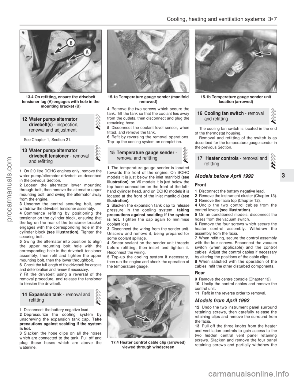
4Commence refitting by positioning the
tensioner on the cylinder block, ensuring that
the lug on the rear of the tensioner bracket
engages with the corresponding hole in the
cylinder block (see illustration). Tighten the
securing bolt.
5Swing the alternator into position to align
the upper mounting bolt hole with the
corresponding hole in the drivebelt tensioner
assembly, then refit and tighten the upper
mounting bolt, then the lower throughbolt.
6Check the full length of the drivebelt for cracks
and deterioration and renew if necessary.
7Fit the drivebelt using a reversal of the
removal procedure, and release the tensioner
to tension the drivebelt.
1Disconnect the battery negative lead.
2Depressurize the cooling system by
unscrewing the expansion tank cap. Take
precautions against scalding if the system
is hot.
3Slacken the hose clips on all the hoses
which are connected to the tank. Pull off and
plug those hoses which are above the
waterline.4Remove the two screws which secure the
tank. Tilt the tank so that the coolant lies away
from the outlets, then disconnect and plug the
remaining hose.
5Disconnect the coolant level sensor, when
fitted, and remove the tank.
6Refit by reversing the removal operations.
Top-up the cooling system on completion.
1The temperature gauge sender is located
towards the front of the engine. On SOHC
models it is just below the inlet manifold (see
illustration); on V6 models it is just below the
top hose connection on the front of the left-
hand cylinder head, and on DOHC models it is
located at the front of the inlet manifold (see
illustration).
2Slacken the expansion tank cap to release
pressure in the cooling system, taking
precautions against scalding if the system
is hot.Tighten the cap again to minimise
coolant loss.
3Disconnect the wiring from the sender unit.
Unscrew and remove it, being prepared for
some coolant spillage.
4Smear sealant on the sender unit threads
before refitting, then insert and tighten it.
Reconnect the wiring.
5Top-up the cooling system if necessary,
then run the engine and check the operation of
the temperature gauge.The cooling fan switch is located in the end
of the thermostat housing.
Removal and refitting of the switch is as
described for the temperature gauge sender in
the previous Section.
Models before April 1992
Front
1Disconnect the battery negative lead.
2Remove the instrument cluster (Chapter 13).
3Remove the facia top (Chapter 12).
4Unclip the two control cables from the
control levers (see illustration).
5On air conditioned models, disconnect the
hoses from the vacuum switch.
6Remove the four screws which secure the
heater control assembly. Withdraw the
assembly from the facia.
7When refitting, secure the control assembly
with the four screws. Reconnect the vacuum
switch (when applicable) and the control
cables. Adjust the control cables if necessary
by altering the positions of the cable clips.
8When satisfied with the operation of the
cables, refit the other disturbed components.
Rear
9Remove the centre console (Chapter 12).
10Unclip the control cables and remove the
control unit.
11Refit in the reverse order to removal.
Models from April 1992
12Undo the two instrument panel surround
retaining screws, then carefully release the
retaining clips and remove the surround from
the facia.
13Pull off the three knobs from the heater
and ventilation controls to gain access to the
two hidden central vent panel retaining
screws. Slacken and remove the four panel
retaining screws and partially withdraw the
17Heater controls - removal and
refitting
16Cooling fan switch - removal
and refitting
15Temperature gauge sender -
removal and refitting
14Expansion tank - removal and
refitting
13Water pump/alternator
drivebelt tensioner - removal
and refitting
12Water pump/alternator
drivebelt(s) - inspection,
renewal and adjustment
Cooling, heating and ventilation systems 3•7
3
13.4 On refitting, ensure the drivebelt
tensioner lug (A) engages with hole in the
mounting bracket (B)15.1a Temperature gauge sender (manifold
removed)15.1b Temperature gauge sender unit
location (arrowed)
17.4 Heater control cable clip (arrowed)
viewed through windscreen
procarmanuals.com
Page 121 of 255
1Disconnect the battery negative (earth) lead.
2Disconnect the battery positive leads. These
may be protected by a plastic cover. Do not
allow the spanner to bridge the positive and
negative terminals.
3Release the battery hold-down clamp. Lift
out the battery. Keep it upright and be careful
not to drop it - it is heavy.
4Commence by placing the battery in its tray,
making sure it is the right way round. Secure it
with the hold-down clamp.
5Clean the battery terminals if necessary
then reconnect them. Connect the positive
lead first, then the negative lead.
1Should it appear that the alternator is not
charging the battery, check first that the
drivebelt is intact and in good condition and
that its tension is correct. Also check the
condition and security of the alternator
electrical connections and the battery leads.
2Accurate assessment of alternator output
requires special equipment and a degree of
skill. A rough idea of whether output is
adequate can be gained by using a voltmeter
(range 0 to 15 or 0 to 20 volts) as follows.
3Connect the voltmeter across the battery
terminals. Switch on the headlights and note
the voltage reading: it should be between 12
and 13 volts.
4Start the engine and run it at a fast idle
(approx 1500 rpm). Read the voltmeter: it
should indicate 13 to 14 volts.
5With the engine still running at a fast idle,
switch on as many electrical consumers as
possible (heated rear window, heater blower
etc). The voltage at the battery should be
maintained at 13 to 14 volts. Increase the
engine speed slightly if necessary to keep the
voltage up.
6If alternator output is low or zero, check the
brushes. If the brushes are OK, seek expert
advice.7Occasionally the condition may arise where
the alternator output is excessive. Clues to this
condition are constantly blowing bulbs;
brightness of lights vary considerably with
engine speed; overheating of alternator and
battery, possible with steam or fumes coming
from the battery. This condition is almost
certainly due to a defective voltage regulator,
but expert advice should be sought.
8Note that the alternator voltage regulator
can be renewed without removing the
alternator from the vehicle. The procedure is
part of brush renewal.
1Disconnect the battery negative lead.
2Disconnect the multi-plug from the rear of
the alternator. It may be secured by a wire clip.
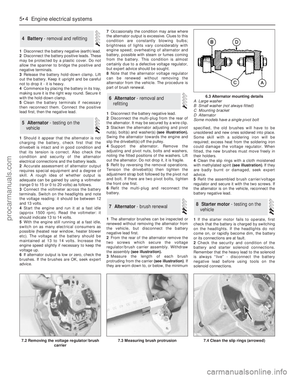
3Slacken the alternator adjusting and pivot
nut(s), bolt(s)and washer(s)(see illustration).
Swing the alternator towards the engine and
slip the drivebelt(s) off the pulley.
4Support the alternator. Remove the
adjusting and pivot nuts, bolts and washers,
noting the fitted positions of the washers. Lift
out the alternator. Do not drop it, it is fragile.
5Refit by reversing the removal operations.
Tension the drivebelt(s) then tighten the
adjustment strap bolt followed by the pivot nut
and bolt. If there are two pivot bolts, tighten
the front one first.
6Refit the multi-plug and reconnect the
battery.
1The alternator brushes can be inspected or
renewed without removing the alternator from
the vehicle, but disconnect the battery
negative lead first.
2From the rear of the alternator remove the
two screws which secure the voltage
regulator/brush carrier assembly. Withdraw
the assembly (see illustration).
3Measure the length of each brush
protruding from the carrier (see illustration). If
they are worn down to, or below, the minimumspecified, the old brushes will have to be
unsoldered and new ones soldered into place.
Some skill with a soldering iron will be
required; excess heat from the soldering iron
could damage the voltage regulator. When
fitted, the new brushes must move freely in
their holders.
4Clean the slip rings with a cloth moistened
with methylated spirit (see illustration). If they
are badly burnt or damaged, seek expert
advice.
5Refit the assembled brush carrier/voltage
regulator and secure it with the two screws. If
the alternator is on the vehicle, reconnect the
battery negative lead.
1If the starter motor fails to operate, first
check that the battery is charged by switching
on the headlights. If the headlights do not
come on, or rapidly become dim, the battery
or its connections are at fault.
2Check the security and condition of the
battery and starter solenoid connections.
Remember that the heavy lead to the solenoid
is always “live” - disconnect the battery
negative lead before using tools on the
solenoid connections.
8Starter motor - testing on the
vehicle7Alternator - brush renewal
6Alternator - removal and
refitting
5Alternator - testing on the
vehicle
4Battery - removal and refitting
5•4Engine electrical systems
7.3 Measuring brush protrusion7.4 Clean the slip rings (arrowed)
6.3 Alternator mounting details
A Large washer
B Small washer (not always fitted)
C Mounting bracket
D Alternator
Some models have a single pivot bolt
7.2 Removing the voltage regulator/brush
carrier
procarmanuals.com
Page 149 of 255
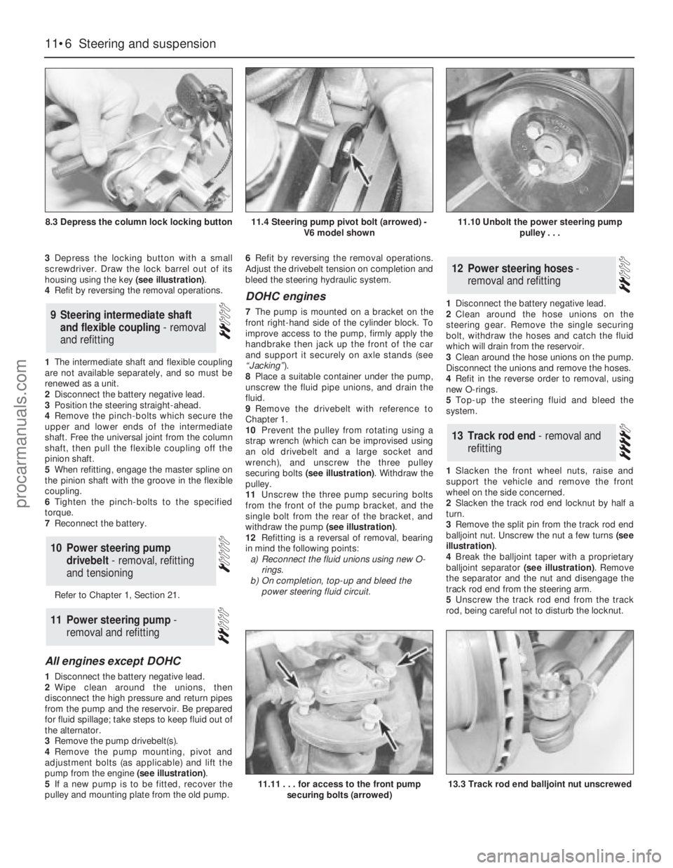
3Depress the locking button with a small
screwdriver. Draw the lock barrel out of its
housing using the key (see illustration).
4Refit by reversing the removal operations.
1The intermediate shaft and flexible coupling
are not available separately, and so must be
renewed as a unit.
2Disconnect the battery negative lead.
3Position the steering straight-ahead.
4Remove the pinch-bolts which secure the
upper and lower ends of the intermediate
shaft. Free the universal joint from the column
shaft, then pull the flexible coupling off the
pinion shaft.
5When refitting, engage the master spline on
the pinion shaft with the groove in the flexible
coupling.
6Tighten the pinch-bolts to the specified
torque.
7Reconnect the battery.
Refer to Chapter 1, Section 21.
All engines except DOHC
1Disconnect the battery negative lead.
2Wipe clean around the unions, then
disconnect the high pressure and return pipes
from the pump and the reservoir. Be prepared
for fluid spillage; take steps to keep fluid out of
the alternator.
3Remove the pump drivebelt(s).
4Remove the pump mounting, pivot and
adjustment bolts (as applicable) and lift the
pump from the engine (see illustration).
5If a new pump is to be fitted, recover the
pulley and mounting plate from the old pump.6Refit by reversing the removal operations.
Adjust the drivebelt tension on completion and
bleed the steering hydraulic system.
DOHC engines
7The pump is mounted on a bracket on the
front right-hand side of the cylinder block. To
improve access to the pump, firmly apply the
handbrake then jack up the front of the car
and support it securely on axle stands (see
“Jacking”).
8Place a suitable container under the pump,
unscrew the fluid pipe unions, and drain the
fluid.
9Remove the drivebelt with reference to
Chapter 1.
10Prevent the pulley from rotating using a
strap wrench (which can be improvised using
an old drivebelt and a large socket and
wrench), and unscrew the three pulley
securing bolts (see illustration). Withdraw the
pulley.
11Unscrew the three pump securing bolts
from the front of the pump bracket, and the
single bolt from the rear of the bracket, and
withdraw the pump (see illustration).
12Refitting is a reversal of removal, bearing
in mind the following points:
a)Reconnect the fluid unions using new O-
rings.
b)On completion, top-up and bleed the
power steering fluid circuit.1Disconnect the battery negative lead.
2Clean around the hose unions on the
steering gear. Remove the single securing
bolt, withdraw the hoses and catch the fluid
which will drain from the reservoir.
3Clean around the hose unions on the pump.
Disconnect the unions and remove the hoses.
4Refit in the reverse order to removal, using
new O-rings.
5Top-up the steering fluid and bleed the
system.
1Slacken the front wheel nuts, raise and
support the vehicle and remove the front
wheel on the side concerned.
2Slacken the track rod end locknut by half a
turn.
3Remove the split pin from the track rod end
balljoint nut. Unscrew the nut a few turns (see
illustration).
4Break the balljoint taper with a proprietary
balljoint separator (see illustration). Remove
the separator and the nut and disengage the
track rod end from the steering arm.
5Unscrew the track rod end from the track
rod, being careful not to disturb the locknut.
13Track rod end - removal and
refitting
12Power steering hoses -
removal and refitting
11Power steering pump -
removal and refitting
10Power steering pump
drivebelt - removal, refitting
and tensioning
9Steering intermediate shaft
and flexible coupling - removal
and refitting
11•6Steering and suspension
8.3 Depress the column lock locking button
11.11 . . . for access to the front pump
securing bolts (arrowed)13.3 Track rod end balljoint nut unscrewed
11.4 Steering pump pivot bolt (arrowed) -
V6 model shown11.10 Unbolt the power steering pump
pulley . . .
procarmanuals.com
Page 180 of 255
The electrical system is a 12 volt, negative
earth type. Electricity is generated by an
alternator, belt-driven from the crankshaft pulley.
A lead-acid battery provides a reserve of power
for starting and when the demands of the system
temporarily exceed the alternator output.
The battery negative terminal is connected
to “earth” - vehicle metal - and most electrical
system components are wired so that they
only receive a positive feed, the current
returning via vehicle metal. This means that
the component mounting forms part of the
circuit. Loose or corroded mountings can
therefore cause apparent electrical faults.
Many semiconductor devices are used in
the electrical system, both in the “black
boxes” which control vehicle functions and in
other components. Semiconductors are very
sensitive to excessive (or wrong polarity)
voltage, and to extremes of heat. Observe the
appropriate precautions to avoid damage.
Although some repair procedures are given
in this Chapter, sometimes renewal of a well-
used item will prove more satisfactory. The
reader whose interests extend beyond
component renewal should obtain a copy of
the “Automobile Electrical Manual”, available
from the publishers of this book.
Before starting work on the electrical
system, read the precautions listed in “Safety
first!” at the beginning of the manual.
Note:Refer to the precautions given in “Safety
first!” and in Section 1 of this Chapter before
starting work. The following tests relate to testing
of the main electrical circuits, and should not be
used to test delicate electronic circuits (such as
anti-lock braking systems), particularly where an
electronic control unit (ECU) is involved.
General
1A typical electrical circuit consists of an
electrical component, any switches, relays,
motors, fuses, fusible links or circuit breakers
related to that component, and the wiring and
connectors which link the component to both
the battery and the chassis. To help to
pinpoint a problem in an electrical circuit,
wiring diagrams are included at the end of this
Chapter.
2Before attempting to diagnose an electrical
fault, first study the appropriate wiring
diagram, to obtain a more complete
understanding of the components included in
the particular circuit concerned. The possible
sources of a fault can be narrowed down by
noting whether other components related to
the circuit are operating properly. If several
components or circuits fail at one time, the
problem is likely to be related to a shared fuse
or earth connection.
3Electrical problems usually stem from
simple causes, such as loose or corroded
connections, a faulty earth connection, a
blown fuse, a melted fusible link, or a faulty
relay. Visually inspect the condition of all
fuses, wires and connections in a problem
circuit before testing the components. Use the
wiring diagrams to determine which terminal
connections will need to be checked in order
to pinpoint the trouble-spot.
4The basic tools required for electrical fault-
finding include: a circuit tester or voltmeter (a
12-volt bulb with a set of test leads can also
be used for certain tests), a self-powered test
light (sometimes known as a continuity tester),
an ohmmeter (to measure resistance), a
battery and set of test leads, and a jumper
wire, preferably with a circuit breaker or fuse
incorporated, which can be used to bypass
suspect wires or electrical components.
Before attempting to locate a problem with
test instruments, use the wiring diagram to
determine where to make the connections.
5To find the source of an intermittent wiring
fault (usually due to a poor or dirty connection,
or damaged wiring insulation), an integrity testcan be performed on the wiring, which
involves moving the wiring by hand, to see if
the fault occurs as the wiring is moved. It
should be possible to narrow down the source
of the fault to a particular section of wiring.
This method of testing can be used in
conjunction with any of the tests described in
the following sub-Sections.
6Apart from problems due to poor
connections, two basic types of fault can
occur in an electrical circuit - open-circuit or
short-circuit.
7Open-circuit faults are caused by a break
somewhere in the circuit, which prevents
current from flowing. An open-circuit fault will
prevent a component from working, but will
not cause the relevant circuit fuse to blow.
8Short-circuit faults are caused by a “short”
somewhere in the circuit, which allows the
current flowing in the circuit to “escape” along
an alternative route, usually to earth. Short-
circuit faults are normally caused by a
breakdown in wiring insulation, which allows a
feed wire to touch either another wire, or an
earthed component such as the bodyshell. A
short-circuit fault will normally cause the
relevant circuit fuse to blow. Note: A short-
circuit that occurs in the wiring between a
circuit’s battery supply and its fuse will not
cause the fuse in that particular circuit to blow.
This part of the circuit is unprotected - bear
this in mind when fault-finding on the vehicle’s
electrical system.
Finding an open-circuit
9To check for an open-circuit, connect one
lead of a circuit tester or voltmeter to either the
negative battery terminal or a known good earth.
10Connect the other lead to a connector in
the circuit being tested, preferably nearest to
the battery or fuse.
11Switch on the circuit, bearing in mind that
some circuits are live only when the ignition
switch is moved to a particular position.
12If voltage is present (indicated either by
the tester bulb lighting or a voltmeter reading,
as applicable), this means that the section of
2Electrical fault-finding - general
information
1General information
Body electrical system 13•3
13
Other relays and modules (continued)
IdentificationFunction
Behind facia (passenger side) (continued):
M4 . . . . . . . . . . . . . . . . . . . . . . . . . . . . . . . . . . . . . . . . . . . . . . . . . . . .Heated windscreen (timer)
M5 . . . . . . . . . . . . . . . . . . . . . . . . . . . . . . . . . . . . . . . . . . . . . . . . . . . .Air conditioning cooling fan
M6 . . . . . . . . . . . . . . . . . . . . . . . . . . . . . . . . . . . . . . . . . . . . . . . . . . . .ABS pump relay
M7 . . . . . . . . . . . . . . . . . . . . . . . . . . . . . . . . . . . . . . . . . . . . . . . . . . . .ABS main relay
M8 . . . . . . . . . . . . . . . . . . . . . . . . . . . . . . . . . . . . . . . . . . . . . . . . . . . .ABS control unit
M9 . . . . . . . . . . . . . . . . . . . . . . . . . . . . . . . . . . . . . . . . . . . . . . . . . . . .Ride height control
Below instrument panel (driver’s side):
N1 . . . . . . . . . . . . . . . . . . . . . . . . . . . . . . . . . . . . . . . . . . . . . . . . . . . .Bulb failure warning unit
Below facia (passenger side):
P1 . . . . . . . . . . . . . . . . . . . . . . . . . . . . . . . . . . . . . . . . . . . . . . . . . . . .ABS module
P2 . . . . . . . . . . . . . . . . . . . . . . . . . . . . . . . . . . . . . . . . . . . . . . . . . . . .Fuel-injection system module
Behind facia (passenger side):
R1 . . . . . . . . . . . . . . . . . . . . . . . . . . . . . . . . . . . . . . . . . . . . . . . . . . . .Speed control system module
R2 . . . . . . . . . . . . . . . . . . . . . . . . . . . . . . . . . . . . . . . . . . . . . . . . . . . .Auxiliary warning system module
R3 . . . . . . . . . . . . . . . . . . . . . . . . . . . . . . . . . . . . . . . . . . . . . . . . . . . .Rear audio console module
Torque wrench settingsNmlbf ft
Alternator adjusting strap:
To steering pump bracket (SOHC) . . . . . . . . . . . . . . . . . . . . . . . . . . .21 to 2616 to 19
To front cover (V6) . . . . . . . . . . . . . . . . . . . . . . . . . . . . . . . . . . . . . . . .41 to 5130 to 38
procarmanuals.com
Page 242 of 255
Engine misfires throughout the driving speed range
m mFuel filter choked (Chapter 1).
m mFuel pump faulty, or delivery pressure low (Chapter 4).
m mFuel tank vent blocked, or fuel pipes restricted (Chapter 4).
m mVacuum leak at the throttle body, inlet manifold or associated hoses
(Chapter 4).
m mWorn, faulty or incorrectly-gapped spark plugs (Chapter 1).
m mFaulty spark plug HT leads (Chapter 5).
m mDistributor cap cracked or tracking internally (Chapter 5).
m mFaulty ignition coil (Chapter 5).
m mUneven or low cylinder compressions (Chapter 2).
m mFuel injection system fault (Chapter 4).
Engine hesitates on acceleration
m
mWorn, faulty or incorrectly-gapped spark plugs (Chapter 1).
m mVacuum leak at the throttle body, inlet manifold or associated hoses
(Chapter 4).
m mFuel injection system fault (Chapter 4).
Engine stalls
m
mVacuum leak at the throttle body, inlet manifold or associated hoses
(Chapter 4).
m mFuel filter choked (Chapter 1).
m mFuel pump faulty, or delivery pressure low (Chapter 4).
m mFuel tank vent blocked, or fuel pipes restricted (Chapter 4).
m mFuel injection system fault (Chapter 4).
Engine lacks power
m
mFuel filter choked (Chapter 1).
m mFuel pump faulty, or delivery pressure low (Chapter 4).
m mUneven or low cylinder compressions (Chapter 2).
m mWorn, faulty or incorrectly-gapped spark plugs (Chapter 1).
m mVacuum leak at the throttle body, inlet manifold or associated hoses
(Chapter 4).
m mFuel injection system fault (Chapter 4).
m mBrakes binding (Chapters 1 and 10).
m mClutch slipping (Chapter 6).
Engine backfires
m
mVacuum leak at the throttle body, inlet manifold or associated hoses
(Chapter 4).
m mFuel injection system fault (Chapter 4).
Oil pressure warning light illuminated with engine
running
m mLow oil level, or incorrect oil grade (Chapter 1).
m mFaulty oil pressure sensor (Chapter 2).
m mWorn engine bearings and/or oil pump (Chapter 2).
m mExcessively high engine operating temperature (Chapter 3).
m mOil pressure relief valve defective (Chapter 2).
m mOil pick-up strainer clogged (Chapter 2).
Note:Low oil pressure in a high-mileage engine at tickover is not
necessarily a cause for concern. Sudden pressure loss at speed is far
more significant. In any event, check the gauge or warning light sender
before condemning the engine.
Engine runs-on after switching off
m mExcessive carbon build-up in engine (Chapter 2).
m mExcessively high engine operating temperature (Chapter 3).
Engine noises
Pre-ignition (pinking) or knocking during acceleration or
under load
m mIgnition timing incorrect/ignition system fault (Chapters 1 and 5).
m mIncorrect grade of spark plug (Chapter 1).
m mIncorrect grade of fuel (Chapter 1).
m mVacuum leak at throttle body, inlet manifold or associated hoses
(Chapter 4).
m mExcessive carbon build-up in engine (Chapter 2).
m mFuel injection system fault (Chapter 4).
Whistling or wheezing noises
m
mLeaking inlet manifold or throttle body gasket (Chapter 4).
m mLeaking exhaust manifold gasket (Chapter 4).
m mLeaking vacuum hose (Chapters 4 and 10).
m mBlowing cylinder head gasket (Chapter 2).
Tapping or rattling noises
m
mWorn valve gear, timing chain, camshaft or hydraulic tappets
(Chapter 2).
m mAncillary component fault (water pump, alternator, etc) (Chapters 3,
5, etc).
Knocking or thumping noises
m mWorn big-end bearings (regular heavy knocking, perhaps less under
load) (Chapter 2).
m mWorn main bearings (rumbling and knocking, perhaps worsening
under load) (Chapter 2).
m mPiston slap (most noticeable when cold) (Chapter 2).
m mAncillary component fault (water pump, alternator, etc) (Chapters 3,
5, etc).
REF•7Fault Finding
2Cooling system
Overheating
m
mAuxiliary drivebelt broken or incorrectly adjusted (Chapter 1).
m mInsufficient coolant in system (Chapter 1).
m mThermostat faulty (Chapter 3).
m mRadiator core blocked, or grille restricted (Chapter 3).
m mElectric cooling fan or thermostatic switch faulty (Chapter 3).
m mViscous-coupled fan faulty (Chapter 3).
m mIgnition timing incorrect, or ignition system fault (Chapters 1 and 5).
m mInaccurate temperature gauge sender unit (Chapter 3).
m mAirlock in cooling system (Chapter 3).
Overcooling
m
mThermostat faulty (Chapter 3).
m mInaccurate temperature gauge sender unit (Chapter 3).
External coolant leakage
m
mDeteriorated or damaged hoses or hose clips (Chapter 1).
m mRadiator core or heater matrix leaking (Chapter 3).
m mPressure cap faulty (Chapter 3).
m mWater pump internal seal leaking (Chapter 3).
m mWater pump-to-block seal leaking (Chapter 3).
m mBoiling due to overheating (Chapter 3).
m mCore plug leaking (Chapter 2).
Internal coolant leakage
m
mLeaking cylinder head gasket (Chapter 2).
m mCracked cylinder head or cylinder block (Chapter 2).
Corrosion
m
mInfrequent draining and flushing (Chapter 1).
m mIncorrect coolant mixture or inappropriate coolant type (Chapter 1).
procarmanuals.com
Page 246 of 255
Ignition/no-charge warning light remains illuminated
with engine running
m m
Auxiliary drivebelt broken, worn, or incorrectly adjusted (Chapter 1).m
mAlternator brushes worn, sticking, or dirty (Chapter 5).m
mAlternator brush springs weak or broken (Chapter 5).m
mInternal fault in alternator or voltage regulator (Chapter 5).m
mBroken, disconnected, or loose wiring in charging circuit (Chapter 5).
Ignition/no-charge warning light fails to come on
m m
Warning light bulb blown (Chapter 13).m
mBroken, disconnected, or loose wiring in warning light circuit
(Chapter 13).
m mAlternator faulty (Chapter 5).
Battery will not hold a charge for more than a few days
m m
Battery defective internally (Chapter 5).m
mBattery electrolyte level low - where applicable (Chapter 1).m
mBattery terminal connections loose or corroded (Chapter 1).m
mAuxiliary drivebelt worn - or incorrectly adjusted, where applicable
(Chapter 1).
m mAlternator not charging at correct output (Chapter 5).m
mAlternator or voltage regulator faulty (Chapter 5).m
mShort-circuit causing continual battery drain (Chapters 5 and 13).
Instrument readings inaccurate or erratic
Instrument readings increase with engine speed
m
mFaulty voltage regulator (Chapter 13).
Fuel or temperature gauges give no reading
m
mFaulty gauge sender unit (Chapters 4 and 5).m
mWiring open-circuit (Chapter 13).m
mFaulty gauge (Chapter 13).
Fuel or temperature gauges give continuous maximum
reading
m mFaulty gauge sender unit (Chapters 4 and 5).m
mWiring short-circuit (Chapter 13).m
mFaulty gauge (Chapter 13).
Horn inoperative, or unsatisfactory in operation
Horn operates all the time
m
mHorn contacts permanently bridged or horn push stuck down
(Chapter 13).
Horn fails to operate
m mBlown fuse (Chapter 13).m
mCable or cable connections loose, broken or disconnected
(Chapter 13).
m mFaulty horn (Chapter 13).
Horn emits intermittent or unsatisfactory sound
m
mCable connections loose (Chapter 13).m
mHorn mountings loose (Chapter 13).m
mFaulty horn (Chapter 13).
Windscreen/tailgate wipers inoperative, or
unsatisfactory in operation
Wipers fail to operate, or operate very slowly
m mWiper blades stuck to screen, or linkage seized or binding
(Chapters 1 and 13).
m mBlown fuse (Chapter 13).m
mCable or cable connections loose, broken or disconnected
(Chapter 13).
m mFaulty relay (Chapter 13).m
mFaulty wiper motor (Chapter 13).
Wiper blades sweep over too large or too small an area of
the glass
m mWiper arms incorrectly positioned on spindles (Chapter 1).m
mExcessive wear of wiper linkage (Chapter 13).m
mWiper motor or linkage mountings loose or insecure (Chapter 13).
Wiper blades fail to clean the glass effectively
m
mWiper blade rubbers worn or perished (Chapter 1).m
mWiper arm tension springs broken, or arm pivots seized (Chapter 13).m
mInsufficient windscreen washer additive to adequately remove road
film (Chapter 1).
Windscreen/tailgate washers inoperative, or
unsatisfactory in operation
One or more washer jets inoperative
m mBlocked washer jet (Chapter 1).m
mDisconnected, kinked or restricted fluid hose (Chapter 13).m
mInsufficient fluid in washer reservoir (Chapter 1).
Washer pump fails to operate
m
mBroken or disconnected wiring or connections (Chapter 13).m
mBlown fuse (Chapter 13).m
mFaulty washer switch (Chapter 13).m
mFaulty washer pump (Chapter 13).
Washer pump runs for some time before fluid is emitted
from jets
m mFaulty one-way valve in fluid supply hose (Chapter 13).
Electric windows inoperative, or unsatisfactory in
operation
Window glass will only move in one direction
m mFaulty switch (Chapter 13).
Window glass slow to move
m
mRegulator seized or damaged, or in need of lubrication (Chapter 12).m
mDoor internal components or trim fouling regulator (Chapter 12).m
mFaulty motor (Chapter 12).
Window glass fails to move
m
mBlown fuse (Chapter 13).m
mFaulty relay (Chapter 13).m
mBroken or disconnected wiring or connections (Chapter 13).m
mFaulty motor (Chapter 13).
Central locking system inoperative, or unsatisfactory
in operation
Complete system failure
m mBlown fuse (Chapter 13).m
mFaulty relay (Chapter 13).m
mBroken or disconnected wiring or connections (Chapter 13).
Latch locks but will not unlock, or unlocks but will not lock
m
mFaulty switch (Chapter 13).m
mBroken or disconnected latch operating rods or levers (Chapter 12).m
mFaulty relay (Chapter 13).
One solenoid/motor fails to operate
m
mBroken or disconnected wiring or connections (Chapter 13).m
mFaulty solenoid/motor (Chapter 12).m
mBroken, binding or disconnected latch operating rods or levers
(Chapter 12).
m mFault in door latch (Chapter 12).
REF•11Fault Finding
procarmanuals.com