1985 FORD GRANADA steering wheel adjustment
[x] Cancel search: steering wheel adjustmentPage 150 of 255
6When refitting, screw the track rod end onto
the track rod as far as the locknut, then back it
off half a turn.
7Insert the ball-pin into the steering arm.
Tighten the balljoint nut to the specified torque
and secure with a new split pin. Nip up the
track rod end locknut, but do not tighten it fully
yet.
8Refit the roadwheel, lower the vehicle and
tighten the wheel nuts to the specified torque.
9Check the toe setting as described in the
following Section. (This may not be strictly
necessary if the same track rod end has been
refitted, but is certainly advisable if any
components have been renewed.)
10Tighten the track rod end locknut when
toe is correct.
1Front wheel alignment is defined by camber,
castor, steering axis inclination and toe
setting. The first three factors are determined
in production; only toe can be adjusted in
service. Incorrect toe will cause rapid tyre
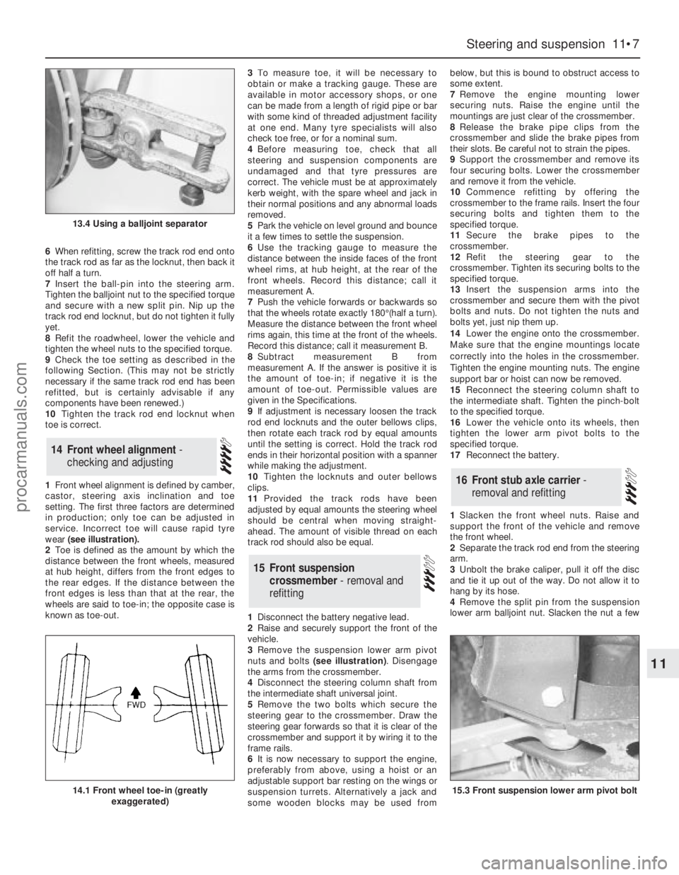
wear (see illustration).
2Toe is defined as the amount by which the
distance between the front wheels, measured
at hub height, differs from the front edges to
the rear edges. If the distance between the
front edges is less than that at the rear, the
wheels are said to toe-in; the opposite case is
known as toe-out.3To measure toe, it will be necessary to
obtain or make a tracking gauge. These are
available in motor accessory shops, or one
can be made from a length of rigid pipe or bar
with some kind of threaded adjustment facility
at one end. Many tyre specialists will also
check toe free, or for a nominal sum.
4Before measuring toe, check that all
steering and suspension components are
undamaged and that tyre pressures are
correct. The vehicle must be at approximately
kerb weight, with the spare wheel and jack in
their normal positions and any abnormal loads
removed.
5Park the vehicle on level ground and bounce
it a few times to settle the suspension.
6Use the tracking gauge to measure the
distance between the inside faces of the front
wheel rims, at hub height, at the rear of the
front wheels. Record this distance; call it
measurement A.
7Push the vehicle forwards or backwards so
that the wheels rotate exactly 180°(half a turn).
Measure the distance between the front wheel
rims again, this time at the front of the wheels.
Record this distance; call it measurement B.
8Subtract measurement B from
measurement A. If the answer is positive it is
the amount of toe-in; if negative it is the
amount of toe-out. Permissible values are
given in the Specifications.
9If adjustment is necessary loosen the track
rod end locknuts and the outer bellows clips,
then rotate each track rod by equal amounts
until the setting is correct. Hold the track rod
ends in their horizontal position with a spanner
while making the adjustment.
10Tighten the locknuts and outer bellows
clips.
11Provided the track rods have been
adjusted by equal amounts the steering wheel
should be central when moving straight-
ahead. The amount of visible thread on each
track rod should also be equal.
1Disconnect the battery negative lead.
2Raise and securely support the front of the
vehicle.
3Remove the suspension lower arm pivot
nuts and bolts (see illustration). Disengage
the arms from the crossmember.
4Disconnect the steering column shaft from
the intermediate shaft universal joint.
5Remove the two bolts which secure the
steering gear to the crossmember. Draw the
steering gear forwards so that it is clear of the
crossmember and support it by wiring it to the
frame rails.
6It is now necessary to support the engine,
preferably from above, using a hoist or an
adjustable support bar resting on the wings or
suspension turrets. Alternatively a jack and
some wooden blocks may be used frombelow, but this is bound to obstruct access to
some extent.
7Remove the engine mounting lower
securing nuts. Raise the engine until the
mountings are just clear of the crossmember.
8Release the brake pipe clips from the
crossmember and slide the brake pipes from
their slots. Be careful not to strain the pipes.
9Support the crossmember and remove its
four securing bolts. Lower the crossmember
and remove it from the vehicle.
10Commence refitting by offering the
crossmember to the frame rails. Insert the four
securing bolts and tighten them to the
specified torque.
11Secure the brake pipes to the
crossmember.
12Refit the steering gear to the
crossmember. Tighten its securing bolts to the
specified torque.
13Insert the suspension arms into the
crossmember and secure them with the pivot
bolts and nuts. Do not tighten the nuts and
bolts yet, just nip them up.
14Lower the engine onto the crossmember.
Make sure that the engine mountings locate
correctly into the holes in the crossmember.
Tighten the engine mounting nuts. The engine
support bar or hoist can now be removed.
15Reconnect the steering column shaft to
the intermediate shaft. Tighten the pinch-bolt
to the specified torque.
16Lower the vehicle onto its wheels, then
tighten the lower arm pivot bolts to the
specified torque.
17Reconnect the battery.
1Slacken the front wheel nuts. Raise and
support the front of the vehicle and remove
the front wheel.
2Separate the track rod end from the steering
arm.
3Unbolt the brake caliper, pull it off the disc
and tie it up out of the way. Do not allow it to
hang by its hose.
4Remove the split pin from the suspension
lower arm balljoint nut. Slacken the nut a few
16Front stub axle carrier -
removal and refitting
15Front suspension
crossmember - removal and
refitting
14Front wheel alignment -
checking and adjusting
Steering and suspension 11•7
11
13.4 Using a balljoint separator
14.1 Front wheel toe-in (greatly
exaggerated)15.3 Front suspension lower arm pivot bolt
procarmanuals.com
Page 151 of 255
times, then use a proprietary balljoint
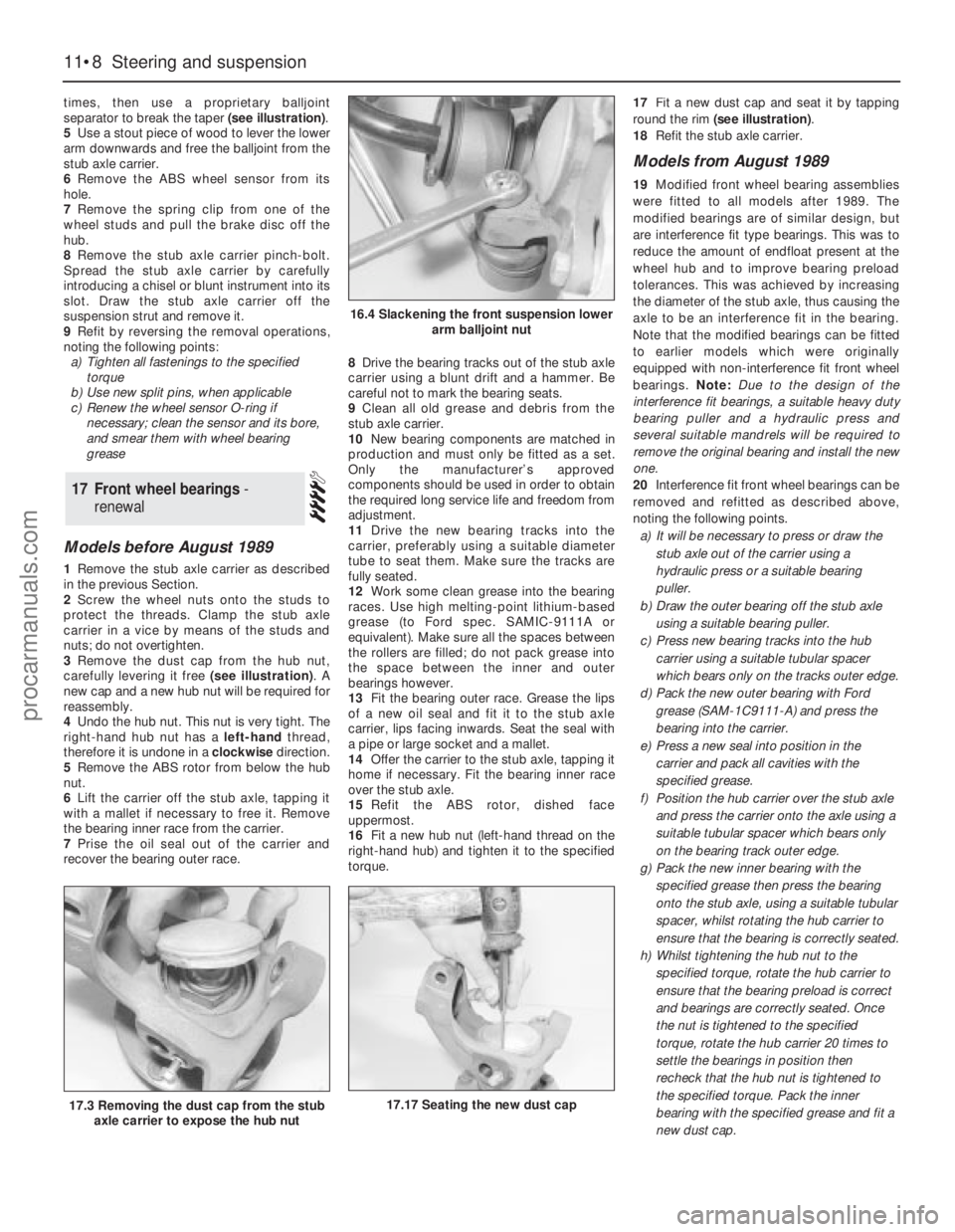
separator to break the taper (see illustration).
5Use a stout piece of wood to lever the lower
arm downwards and free the balljoint from the
stub axle carrier.
6Remove the ABS wheel sensor from its
hole.
7Remove the spring clip from one of the
wheel studs and pull the brake disc off the
hub.
8Remove the stub axle carrier pinch-bolt.
Spread the stub axle carrier by carefully
introducing a chisel or blunt instrument into its
slot. Draw the stub axle carrier off the
suspension strut and remove it.
9Refit by reversing the removal operations,
noting the following points:
a)Tighten all fastenings to the specified
torque
b)Use new split pins, when applicable
c)Renew the wheel sensor O-ring if
necessary; clean the sensor and its bore,
and smear them with wheel bearing
grease
Models before August 1989
1Remove the stub axle carrier as described
in the previous Section.
2Screw the wheel nuts onto the studs to
protect the threads. Clamp the stub axle
carrier in a vice by means of the studs and
nuts; do not overtighten.
3Remove the dust cap from the hub nut,
carefully levering it free (see illustration). A
new cap and a new hub nut will be required for
reassembly.
4Undo the hub nut. This nut is very tight. The
right-hand hub nut has a left-handthread,
therefore it is undone in a clockwisedirection.
5Remove the ABS rotor from below the hub
nut.
6Lift the carrier off the stub axle, tapping it
with a mallet if necessary to free it. Remove
the bearing inner race from the carrier.
7Prise the oil seal out of the carrier and
recover the bearing outer race.8Drive the bearing tracks out of the stub axle
carrier using a blunt drift and a hammer. Be
careful not to mark the bearing seats.
9Clean all old grease and debris from the
stub axle carrier.
10New bearing components are matched in
production and must only be fitted as a set.
Only the manufacturer’s approved
components should be used in order to obtain
the required long service life and freedom from
adjustment.
11Drive the new bearing tracks into the
carrier, preferably using a suitable diameter
tube to seat them. Make sure the tracks are
fully seated.
12Work some clean grease into the bearing
races. Use high melting-point lithium-based
grease (to Ford spec. SAMIC-9111A or
equivalent). Make sure all the spaces between
the rollers are filled; do not pack grease into
the space between the inner and outer
bearings however.
13Fit the bearing outer race. Grease the lips
of a new oil seal and fit it to the stub axle
carrier, lips facing inwards. Seat the seal with
a pipe or large socket and a mallet.
14Offer the carrier to the stub axle, tapping it
home if necessary. Fit the bearing inner race
over the stub axle.
15Refit the ABS rotor, dished face
uppermost.
16Fit a new hub nut (left-hand thread on the
right-hand hub) and tighten it to the specified
torque.17Fit a new dust cap and seat it by tapping
round the rim (see illustration).
18Refit the stub axle carrier.
Models from August 1989
19Modified front wheel bearing assemblies
were fitted to all models after 1989. The
modified bearings are of similar design, but
are interference fit type bearings. This was to
reduce the amount of endfloat present at the
wheel hub and to improve bearing preload
tolerances. This was achieved by increasing
the diameter of the stub axle, thus causing the
axle to be an interference fit in the bearing.
Note that the modified bearings can be fitted
to earlier models which were originally
equipped with non-interference fit front wheel
bearings. Note: Due to the design of the
interference fit bearings, a suitable heavy duty
bearing puller and a hydraulic press and
several suitable mandrels will be required to
remove the originalbearing and install the new
one.
20Interference fit front wheel bearings can be
removed and refitted as described above,
noting the following points.
a)It will be necessary to press or draw the
stub axle out of the carrier using a
hydraulic press or a suitable bearing
puller.
b)Draw the outer bearing off the stub axle
using a suitable bearing puller.
c)Press new bearing tracks into the hub
carrier using a suitable tubular spacer
which bears only on the tracks outer edge.
d)Pack the new outer bearing with Ford
grease (SAM-1C9111-A) and press the
bearing into the carrier.
e)Press a new seal into position in the
carrier and pack all cavities with the
specified grease.
f)Position the hub carrier over the stub axle
and press the carrier onto the axle using a
suitable tubular spacer which bears only
on the bearing track outer edge.
g)Pack the new inner bearing with the
specified grease then press the bearing
onto the stub axle, using a suitable tubular
spacer, whilst rotating the hub carrier to
ensure that the bearing is correctly seated.
h)Whilst tightening the hub nut to the
specified torque, rotate the hub carrier to
ensure that the bearing preload is correct
and bearings are correctly seated. Once
the nut is tightened to the specified
torque, rotate the hub carrier 20 times to
settle the bearings in position then
recheck that the hub nut is tightened to
the specified torque. Pack the inner
bearing with the specified grease and fit a
new dust cap.
17Front wheel bearings -
renewal
11•8Steering and suspension
16.4 Slackening the front suspension lower
arm balljoint nut
17.17 Seating the new dust cap17.3 Removing the dust cap from the stub
axle carrier to expose the hub nut
procarmanuals.com
Page 240 of 255
The vehicle owner who does his or her own maintenance according
to the recommended service schedules should not have to use this
section of the manual very often. Modern component reliability is such
that, provided those items subject to wear or deterioration are
inspected or renewed at the specified intervals, sudden failure is
comparatively rare. Faults do not usually just happen as a result of
sudden failure, but develop over a period of time. Major mechanical
failures in particular are usually preceded by characteristic symptoms
over hundreds or even thousands of miles. Those components which
do occasionally fail without warning are often small and easily carried
in the vehicle.With any fault-finding, the first step is to decide where to begin
investigations. Sometimes this is obvious, but on other occasions, a
little detective work will be necessary. The owner who makes half a
dozen haphazard adjustments or replacements may be successful in
curing a fault (or its symptoms), but will be none the wiser if the fault
recurs, and ultimately may have spent more time and money than was
necessary. A calm and logical approach will be found to be more
satisfactory in the long run. Always take into account any warning
signs or abnormalities that may have been noticed in the period
preceding the fault - power loss, high or low gauge readings, unusual
smells, etc - and remember that failure of components such as fuses or
REF•5Fault Finding
Engine1
m mEngine fails to rotate when attempting to start
m mStarter motor turns engine slowly
m mEngine rotates, but will not start
m mEngine difficult to start when cold
m mEngine difficult to start when hot
m mStarter motor noisy or excessively-rough in engagement
m mEngine starts, but stops immediately
m mEngine idles erratically
m mEngine misfires at idle speed
m mEngine misfires throughout the driving speed range
m mEngine hesitates on acceleration
m mEngine stalls
m mEngine lacks power
m mEngine backfires
m mOil pressure warning light illuminated with engine running
m mEngine runs-on after switching off
m mEngine noises
Cooling system2
m
mOverheating
m mOvercooling
m mExternal coolant leakage
m mInternal coolant leakage
m mCorrosion
Fuel and exhaust systems3
m
mExcessive fuel consumption
m mFuel leakage and/or fuel odour
m mExcessive noise or fumes from exhaust system
Clutch4
m
mPedal travels to floor - no pressure or very little resistance
m mClutch fails to disengage (unable to select gears)
m mClutch slips (engine speed increases, with no increase in vehicle
speed)
m mJudder as clutch is engaged
m mNoise when depressing or releasing clutch pedal
Manual gearbox5
m
mNoisy in neutral with engine running
m mNoisy in one particular gear
m mDifficulty engaging gears
m mJumps out of gear
m mVibration
m mLubricant leaks
Automatic transmission6
m
mFluid leakage
m mTransmission fluid brown, or has burned smellm mGeneral gear selection problems
m mTransmission will not downshift (kickdown) with accelerator fully
depressed
m mEngine will not start in any gear, or starts in gears other than Park
or Neutral
m mTransmission slips, shifts roughly, is noisy, or has no drive in
forward or reverse gears
Propeller shaft7
m
mClicking or knocking noise on turns (at slow speed on full-lock)
m mVibration when accelerating or decelerating
Final drive and driveshafts8
m
mExcessive final drive noise
m mOil leakage from final drive
m mGrating, knocking or vibration from driveshafts
Braking system9
m
mVehicle pulls to one side under braking
m mNoise (grinding or high-pitched squeal) when brakes applied
m mExcessive brake pedal travel
m mBrake pedal feels spongy when depressed
m mExcessive brake pedal effort required to stop vehicle
m mJudder felt through brake pedal or steering wheel when braking
m mPedal pulsates when braking hard
m mBrakes binding
m mRear wheels locking under normal braking
Suspension and steering systems10
m
mVehicle pulls to one side
m mWheel wobble and vibration
m mExcessive pitching and/or rolling around corners, or during braking
m mWandering or general instability
m mExcessively-stiff steering
m mExcessive play in steering
m mLack of power assistance
m mTyre wear excessive
Electrical system11
m
mLights inoperative
m mIgnition/no-charge warning light remains illuminated with engine
running
m mIgnition/no-charge warning light fails to come on
m mBattery will not hold a charge for more than a few days
m mInstrument readings inaccurate or erratic
m mHorn inoperative, or unsatisfactory in operation
m mWindscreen/tailgate wipers inoperative, or unsatisfactory in
operation
m mWindscreen/tailgate washers inoperative, or unsatisfactory in
operation
m mElectric windows inoperative, or unsatisfactory in operation
m mCentral locking system inoperative, or unsatisfactory in operation
Introduction
procarmanuals.com
Page 244 of 255
Transmission fluid brown, or has burned smell
m m
Transmission fluid level low, or fluid in need of renewal (Chapter 1).
General gear selection problems
m m
The most likely cause of gear selection problems is a faulty or
poorly-adjusted gear selector mechanism. The following are common
problems associated with a faulty selector mechanism:
a)Engine starting in gears other than Park or Neutral.
b)Indicator on gear selector lever pointing to a gear other than
the one actually being used.
c)Vehicle moves when in Park or Neutral.
d)Poor gear shift quality, or erratic gear changes.
m
mRefer any problems to a Ford dealer, or an automatic transmission
specialist.
Transmission will not downshift (kickdown) with
accelerator pedal fully depressed
m m
Low transmission fluid level (Chapter 1).
m
mIncorrect selector adjustment (Chapter 7B).
Engine will not start in any gear, or starts in gears
other than Park or Neutral
m m
Faulty starter inhibitor switch (Chapter 7B).
m
mIncorrect selector adjustment (Chapter 7B).
Transmission slips, shifts roughly, is noisy, or has no
drive in forward or reverse gears
m m
There are many probable causes for the above problems, but the
home mechanic should be concerned with only one possibility - fluid
level. Before taking the vehicle to a dealer or transmission specialist,
check the fluid level and condition of the fluid as described in Chapter 1.
Correct the fluid level as necessary, or change the fluid and filter if
needed. If the problem persists, professional help will be necessary.
REF•9Fault Finding
7Propeller shaft
Clunking or knocking noise when taking up drive
m m
Worn universal joints (Chapter 8).m
mLoose flange bolt (Chapter 8).
Vibration when accelerating or decelerating
m m
Worn centre bearing or universal joints (Chapter 8).m
mBent or distorted shaft (Chapter 8).m
mDeteriorated rubber insulator on centre bearing ( Chapter 8)
8Final drive and driveshafts
Excessive final drive noise
m m
Oil level low, or incorrect grade (Chapter 1)m
mWorn bearings (Chapter 9)m
mWorn or badly adjusted crownwheel and pinion (Chapter 9)m
mLoose or deteriorated final drive mountings (Chapter 9)
Oil leakage from final drive
m m
Pinion or output flange oil seal leaking (Chapter 9)
m
mRear cover leaking (Chapter 9)
m
mCover or casing cracked (Chapter 9)
Grating, knocking or vibration from driveshafts
m m
Flange screws loose (Chapter 9)
m
mCV joints worn (Chapter 9)
m
mDriveshaft bent (Chapter 9)
9Braking system
Note:Make sure that the tyres are in good condition and correctly
inflated, that the front wheel alignment is correct, and that the vehicle is
not loaded with weight in an unequal manner. Apart from checking the
condition of all pipe and hose connections, any faults occurring on the
anti-lock braking system should be referred to a Ford dealer for diagnosis.
Vehicle pulls to one side under braking
m m
Worn, defective, damaged or contaminated front or rear brake
pads on one side (Chapters 1 and 10).
m mSeized or partially-seized front or rear brake caliper piston (Chapter 10).m
mA mixture of brake pad lining materials fitted between sides
(Chapter 10).
m mBrake caliper mounting bolts loose (Chapter 10).m
mWorn or damaged steering or suspension components (Chapters 1
and 11).
Noise (grinding or high-pitched squeal) when brakes
applied
m m
Brake pad friction material worn down to metal backing (Chapters 1
and 10).
m mExcessive corrosion of brake disc - may be apparent after the
vehicle has been standing for some time (Chapters 1 and 10).
Excessive brake pedal travel
m m
Faulty master cylinder (Chapter 10).
m
mAir in hydraulic system (Chapter 10).
m
mFaulty vacuum servo unit (Chapter 10).
Brake pedal feels spongy when depressed
m m
Air in hydraulic system (Chapter 10).
m
mDeteriorated flexible rubber brake hoses (Chapters 1 and 10).
m
mMaster cylinder mountings loose (Chapter 10).
m
mFaulty master cylinder (Chapter 10).
Excessive brake pedal effort required to stop vehicle
m m
Faulty vacuum servo unit (Chapter 10).
m
mDisconnected, damaged or insecure brake servo vacuum hose
(Chapters 1 and 10).
m mPrimary or secondary hydraulic circuit failure (Chapter 10).
m
mSeized brake caliper piston(s) (Chapter 10).
m
mBrake pads incorrectly fitted (Chapter 10).
m
mIncorrect grade of brake pads fitted (Chapter 10).
m
mBrake pads contaminated (Chapter 10).
procarmanuals.com
Page 249 of 255
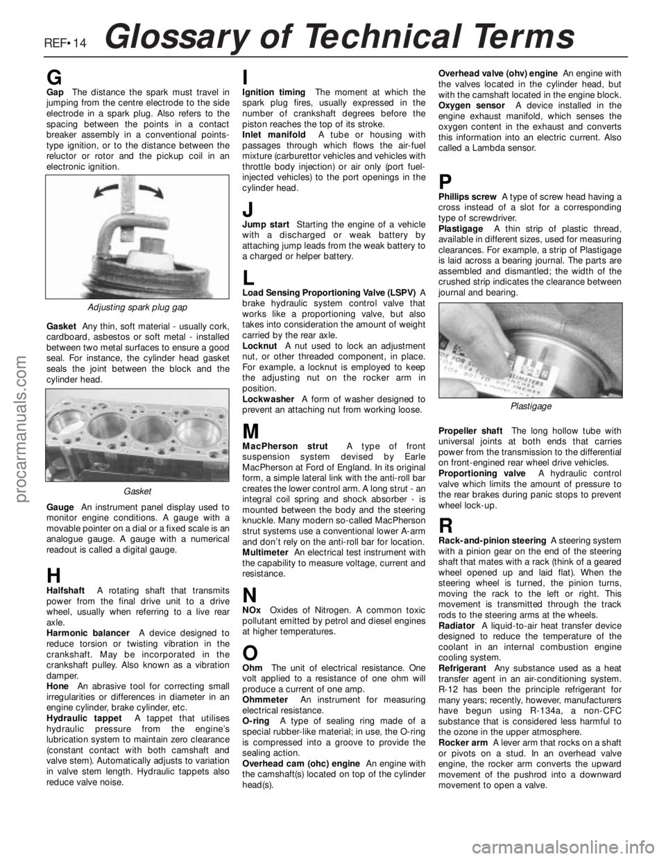
REF•14Glossary of Technical Terms
GGapThe distance the spark must travel in
jumping from the centre electrode to the side
electrode in a spark plug. Also refers to the
spacing between the points in a contact
breaker assembly in a conventional points-
type ignition, or to the distance between the
reluctor or rotor and the pickup coil in an
electronic ignition.
GasketAny thin, soft material - usually cork,
cardboard, asbestos or soft metal - installed
between two metal surfaces to ensure a good
seal. For instance, the cylinder head gasket
seals the joint between the block and the
cylinder head.
GaugeAn instrument panel display used to
monitor engine conditions. A gauge with a
movable pointer on a dial or a fixed scale is an
analogue gauge. A gauge with a numerical
readout is called a digital gauge.
HHalfshaftA rotating shaft that transmits
power from the final drive unit to a drive
wheel, usually when referring to a live rear
axle.
Harmonic balancerA device designed to
reduce torsion or twisting vibration in the
crankshaft. May be incorporated in the
crankshaft pulley. Also known as a vibration
damper.
HoneAn abrasive tool for correcting small
irregularities or differences in diameter in an
engine cylinder, brake cylinder, etc.
Hydraulic tappetA tappet that utilises
hydraulic pressure from the engine’s
lubrication system to maintain zero clearance
(constant contact with both camshaft and
valve stem). Automatically adjusts to variation
in valve stem length. Hydraulic tappets also
reduce valve noise.
IIgnition timingThe moment at which the
spark plug fires, usually expressed in the
number of crankshaft degrees before the
piston reaches the top of its stroke.
Inlet manifoldA tube or housing with
passages through which flows the air-fuel
mixture (carburettor vehicles and vehicles with
throttle body injection) or air only (port fuel-
injected vehicles) to the port openings in the
cylinder head.
JJump startStarting the engine of a vehicle
with a discharged or weak battery by
attaching jump leads from the weak battery to
a charged or helper battery.
LLoad Sensing Proportioning Valve (LSPV)A
brake hydraulic system control valve that
works like a proportioning valve, but also
takes into consideration the amount of weight
carried by the rear axle.
LocknutA nut used to lock an adjustment
nut, or other threaded component, in place.
For example, a locknut is employed to keep
the adjusting nut on the rocker arm in
position.
LockwasherA form of washer designed to
prevent an attaching nut from working loose.
MMacPherson strutA type of front
suspension system devised by Earle
MacPherson at Ford of England. In its original
form, a simple lateral link with the anti-roll bar
creates the lower control arm. A long strut - an
integral coil spring and shock absorber - is
mounted between the body and the steering
knuckle. Many modern so-called MacPherson
strut systems use a conventional lower A-arm
and don’t rely on the anti-roll bar for location.
MultimeterAn electrical test instrument with
the capability to measure voltage, current and
resistance.
NNOxOxides of Nitrogen. A common toxic
pollutant emitted by petrol and diesel engines
at higher temperatures.
OOhmThe unit of electrical resistance. One
volt applied to a resistance of one ohm will
produce a current of one amp.
OhmmeterAn instrument for measuring
electrical resistance.
O-ringA type of sealing ring made of a
special rubber-like material; in use, the O-ring
is compressed into a groove to provide the
sealing action.
Overhead cam (ohc) engineAn engine with
the camshaft(s) located on top of the cylinder
head(s).Overhead valve (ohv) engineAn engine with
the valves located in the cylinder head, but
with the camshaft located in the engine block.
Oxygen sensorA device installed in the
engine exhaust manifold, which senses the
oxygen content in the exhaust and converts
this information into an electric current. Also
called a Lambda sensor.
PPhillips screwA type of screw head having a
cross instead of a slot for a corresponding
type of screwdriver.
PlastigageA thin strip of plastic thread,
available in different sizes, used for measuring
clearances. For example, a strip of Plastigage
is laid across a bearing journal. The parts are
assembled and dismantled; the width of the
crushed strip indicates the clearance between
journal and bearing.
Propeller shaftThe long hollow tube with
universal joints at both ends that carries
power from the transmission to the differential
on front-engined rear wheel drive vehicles.
Proportioning valveA hydraulic control
valve which limits the amount of pressure to
the rear brakes during panic stops to prevent
wheel lock-up.
RRack-and-pinion steeringA steering system
with a pinion gear on the end of the steering
shaft that mates with a rack (think of a geared
wheel opened up and laid flat). When the
steering wheel is turned, the pinion turns,
moving the rack to the left or right. This
movement is transmitted through the track
rods to the steering arms at the wheels.
RadiatorA liquid-to-air heat transfer device
designed to reduce the temperature of the
coolant in an internal combustion engine
cooling system.
RefrigerantAny substance used as a heat
transfer agent in an air-conditioning system.
R-12 has been the principle refrigerant for
many years; recently, however, manufacturers
have begun using R-134a, a non-CFC
substance that is considered less harmful to
the ozone in the upper atmosphere.
Rocker armA lever arm that rocks on a shaft
or pivots on a stud. In an overhead valve
engine, the rocker arm converts the upward
movement of the pushrod into a downward
movement to open a valve.
Adjusting spark plug gap
Plastigage
Gasket
procarmanuals.com
Page 253 of 255
IND•2
F
Facia panels and trim - 12•12
Fast idle speed adjustment - 4•13
Fault finding- REF•5et seq
Fault-finding - electrical system - 5•3, 13•3
Final drive and driveshafts- 1•15, 9•1et
seq, 11•10, REF•9
Fire - 0•5
Flasher switch and unit - 13•11
Fluid leakage - REF•8
Fluid level checks - 1•6
Flywheel ring gear - 2A•14, 2C•15
Flywheel/driveplate - 2A•9, 2A•16, 2B•15,
2C•11, 2C•17
Foglight - 13•5,13•13
Footbrake - 0•11, 0•12
Footwell lights - 13•8
Fuel and exhaust systems- 0•14, 4•1et seq,
REF•8
Fuel computer components - 13•17
Fuel consumption high - REF•8
Fuel filler lock barrel - 12•7
Fuel filler switch - 13•18
Fuel filter - 1•19, 4•14
Fuel flow sensor - 13•18
Fuel gauge gives false reading - REF•11
Fuel odour - REF•8
Fuel pressure regulator - 4•18
Fuel temperature sensor - 5•12
Fuel trap (carburettor models) - 5•9
Fume or gas intoxication - 0•5
Fumes from exhaust system - REF•8
Fuses - 13•13
G
G (gravity) switch - 10•14
Gaskets - REF•4
Gear linkage - 7A•4
Gear selection problems - REF•8, REF•9
Glossary of technical terms - REF•12
Glovebox light - 13•8
Graphic display module - 13•18
Graphic equaliser - 13•21
Grille - 12•9
H
Handbrake “ON” switch - 13•12
Handbrake - 0•11, 10•11
Handles - 12•6
Hazard warning switch - 13•9, 13•13
HC emissions - 0•14
Headlight - 13•4, 13•6, 13•7, 13•11
Headlining - 12•11
Headphone relay - 13•22
Heated rear window switch - 13•13
Heated seat control switches - 13•13
Heater assembly - 3•7, 3•8, 3•9, 3•10,
13•11, 13•20
High frequency units - 13•22
High pressure hose - 10•10
Hinges - 1•12
Horn - 13•10
Horn emits intermittent or unsatisfactory
sound - REF•11Horn fails to operate - REF•11
Horn inoperative, or unsatisfactory in
operation - REF•11
Horn operates all the time - REF•11
Horn switch plate, slip rings and brushes -
13•10
HT leads - 5•5
HT voltage - 5•3
Hub - 11•11
Hydraulic system seals and hoses - 1•19
Hydraulic unit - 10•8, 10•9, 10•10
Hydrofluoric acid - 0•5
I
Idle mixture - 1•10
Idle speed - 1•10, 4•7, 4•9, 4•11, 4•14, 5•11
Idle speed control valve - 4•15
Idle speed linkage - 1•15
Ignition coil - 5•9
Ignition module - 5•8
Ignition system - 1•17
Ignition timing - 5•7, 5•11
Ignition/no-charge warning light fails to
come on - REF•11
Ignition/no-charge warning light remains
illuminated with engine running - REF•11
Ignition/starter switch - 13•11
Inlet manifold - 1•14, 4•19
Instrument cluster - 13•9, 13•10
Instrument illumination dimmer switch - 13•11
Instrument panel lights - 13•8
Instrument readings inaccurate or erratic -
REF•11
Instruments and electrical equipment - 1•16
Intensive maintenance - 1•6
Interior lights - 13•7
Introduction to the Ford Granada - 0•4
J
Jacking - 0•6
Joint mating faces - REF•4
Joystick fader control - 13•22
Jump starting - 0•10
Jumps out of gear - REF•8
L
Latch locks but will not unlock, or unlocks
but will not lock - REF•11
Leaks - 0•8, 1•10
Lighter - 13•10
Lighting master switch - 13•11
Lights - 13•4, 13•6
Lights inoperative - REF•10
Locknuts, locktabs and washers - REF•4
Locks - 1•12, 12•6, 12•7
Loudspeakers - 13•21, 13•22
Low pressure hose - 10•10
Lower arm - 11•9, 11•12
Lubricant leaks - REF•8
Lubricants and fluids - 1•2
Luggage area light - 13•8
M
Main bearings - 2A•11, 2A•15, 2B•17,
2C•12, 2C•15
Maintenance - bodywork and underframe -
12•1
Maintenance - upholstery and carpets -
12•2
Manifold absolute pressure (MAP) sensor -
5•12
Manifold heater - 5•11
Manual gearbox- 1•11, 2B•6, 2B•7, 7A•1et
seq, REF•8
Manual steering - 11•3
Master cylinder - 10•12
Mirror - 0•11, 12•12, 13•11
Mixture adjustment potentiometer - 4•19
Mixture adjustments - 4•7, 4•9, 4•11, 4•14
Motifs and emblems - 12•10
Motor factors - 0•9
Mountings - 2A•11, 2B•8, 2C•12
N
Needle valve and float - 4•11
Number plate light - 13•5
O
Oil - 1•6, 1•9
Oil filler cap - 1•10
Oil filter - 1•9, 2A•11
Oil leakage from final drive - REF•9
Oil pressure warning light illuminated with
engine running - REF•7
Oil pressure warning switch - 13•12
Oil pump - 2A•10, 2A•12, 2A•16, 2B•16,
2B•17, 2C•11, 2C•14, 2C•17
Oil seals - 2A•10, 2B•15, 2C•12, 9•2, 9•3,
REF•4
On load voltage check - 5•5
Open-circuit - 13•3
Overcooling - REF•7
Overhead console - 12•17
Overheating - REF•7
P
Pads - 1•10, 10•4, 10•5
Parcel shelf - 12•19
Parking light - 13•4
Pedal Travel Sensor (PTS) - 10•14
Pedals - 6•2, 4•6, 10•8
Pierburg 2V carburettor - 4•7, 4•9
Pistons and connecting rods - 2A•11, 2A•13,
2A•15, 2B•17, 2C•12, 2C•14, 2C•16
Pitching and/or rolling around corners, or
during braking - REF•10
Plastic components - 12•3
Poisonous or irrirant substances - 0•5
Power steering - 1•16, 11•3, 11•4, 11•6
Power valve diaphragm - 4•12
Pre-ignition (pinking) or knocking during
acceleration or under load - REF•7
Printed circuit board - 13•20
Propeller shaft- 8•1et seq, REF•9
Pushrods - 2C•13
Index
procarmanuals.com
Page 254 of 255
Q
Quarter window moulding - 12•10
R
Radiator - 3•3, 12•9
Radio fader light - 13•8
Radio or radio/cassette player - 13•20, 13•21
Rear light cluster - 13•5, 13•6
Recline motor - 13•15
Regulator mechanism - 12•9
Relays - 13•13
Respraying - 12•3
Reversing light switch - 7B•3, 13•12, 13•13
Ride height control - 11•12, 11•13
Road test - 1•16
Rocker shaft - 2C•12
Rotor arm - 5•5
Routine maintenance and servicing- 1•1et
seq
Rust holes or gashes in bodywork - 12•2
S
Safety first! - 0•5
Scalding - 0•5
Scratches in bodywork - 12•2
Screw threads and fastenings - REF•4
Seals and hoses - 1•19
Seat air cushion - 12•17
Seat belts - 0•12, 1•10, 12•17, 12•18
Seats - 0•12, 12•17, 12•18, 13•10, 13•13,
13•15
Selector rod - 7B•4
Servo - 10•12, 10•13, 13•20
Shock absorbers - 0•12, 0•13, 11•12
Short-circuit - 13•4
Side mouldings - 12•10
Sidelight - 13•4
Sliding roof - 12•5, 13•12, 13•16
Spare parts - 0•8
Spark plugs - 1•12, 5•5
Speakers - 13•21, 13•22
Speed control system components - 13•19,
13•20
Speedometer sender unit - 13•16
Spoiler - 12•11
Springs - 0•13, 11•11
Starter inhibitor/reversing light switch -
7B•3, 13•13
Starter motor - 5•4, 5•5
Starter motor noisy or excessively-rough in
engagement - REF•6
Starter motor turns engine slowly - REF•6
Steering and suspension - 0•12, 0•13, 1•15,
1•16, 11•1et seq,REF•10
Steering column- 0•11, 11•5
Steering gear - 11•3
Steering intermediate shaft and flexible
coupling - 11•6Steering play - REF•10
Steering rack bellows - 11•4
Steering stiff - REF•10
Steering wheel - 0•11, 11•4, 11•5
Steering wheel and column -
Stop-light switch - 13•12
Strut - 11•9, 11•10
Stub axle carrier - 11•7
Sump - 2A•9, 2A•16, 2B•15, 2C•9, 2C•19
Switch illumination lights - 13•8
Switches - 13•9, 13•11, 13•12, 13•13,
13•18, 13•19
T
Tailgate - 12•4, 12•7, 13•12, 13•18
Tailgate wash/wipe inoperative, or
unsatisfactory in operation - REF•11
Tailgate window mouldings - 12•10
Tappets - 2C•13
Temperature gauge gives false reading -
REF•11
Temperature gauge sender - 3•7
Thermostat - 3•3
Throttle body - 4•15
Throttle cable - 4•7
Throttle kicker - 4•13
Throttle pedal - 4•6
Throttle position sensor - 4•15
Timing belt - 2A•8, 2A•14, 2A•18
Timing chain - 2B•8, 2B•10, 2C•9, 2C•17
Tools and working facilities- REF•1et seq
Towing - 0•7
Track rod end - 11•6
Transmission fluid brown, or has burned
smell - REF•9
Transmission slips, shifts roughly, is noisy,
or has no drive in forward or reverse
gears - REF•9
Transmission will not downshift (kickdown)
with accelerator pedal fully depressed -
REF•9
Tyre wear - REF•10
Tyres - 0•14, 1•7
U
Ultrasonic sensor - 13•23
Underbody inspection - 1•15
Unleaded fuel - 4•23
V
Vacuum dump valve/switch - 13•19
Vacuum hoses - 2C•7
Vacuum line modification - 7B•4
Vacuum pull-down adjustment - 4•13
Vacuum pump - 13•20
Vacuum servo - 10•12, 10•13, 13•20
Valve block and pump assembly - 10•13
Valve clearances - 1•13, 2A•20, 2C•21Valve grinding - 2A•14
Vane airflow meter(s) - 4•16
Vanity mirror light - 13•7
Vapour separator - 4•7
Vehicle identification - 0•9, 0•12
Vehicle pulls to one side - REF•9, REF•10
Vehicle speed sensor - 5•12
Vibration damper (MT75type gearbox) - 8•4
Viscous-coupled fan - 3•5
W
Wandering or general instability - REF•10
Warning light bulbs - 13•18
Wash/wipe inoperative, or unsatisfactory in
operation - REF•11
Wash/wipe switch - 13•12
Washer fluid - 1•7, 13•19
Washer jets inoperative - REF•11
Washer pump fails to operate - REF•11
Washer pump runs for some time before
fluid is emitted from jets - REF•11
Water pump - 3•5
Water pump/alternator drivebelt - 3•7
Weatherstrip - 12•7
Weber 2V carburettor - 4•9, 4•10
Weber 2V TLD carburettor - 4•11, 4•12,
4•13
Wheel alignment - 11•7
Wheel bearings - 0•13, 11•8, 11•11
Wheel changing - 0•7
Wheel sensors - 10•12
Wheel stud - 11•11
Wheel wobble and vibration - REF•10
Wheels - 0•14, 1•10
Wheels locking under normal braking -
REF•10
Window frame mouldings - 12•10
Window glass - 12•8
Window glass fails to move - REF•11
Window glass slow to move - REF•11
Window glass will only move in one
direction - REF•11
Window operating motor - 13•15
Window operating switch - 13•12
Windscreen - 0•11, 12•9
Windscreen mouldings - 12•10
Windscreen, rear window and headlight
washer components - 13•17
Wiper arms and blades - 13•16
Wiper blades - 1•9
Wiper blades fail to clean the glass
effectively - REF•11
Wiper blades sweep over too large or too
small an area of the glass - REF•11
Wiper motor - 13•17
Wipers fail to operate, or operate very
slowly - REF•11
Wiring diagrams- WD•0 et seq
Working facilities - REF•3
IND•3Index
procarmanuals.com