1985 FORD GRANADA horn
[x] Cancel search: hornPage 187 of 255
1With the instrument cluster removed, a
particular gauge or other component can be
renewed by following the appropriate parts of
this Section.
2Remove all the light bulbs and holders from
the rear of the panel by twisting them anti-
clockwise.
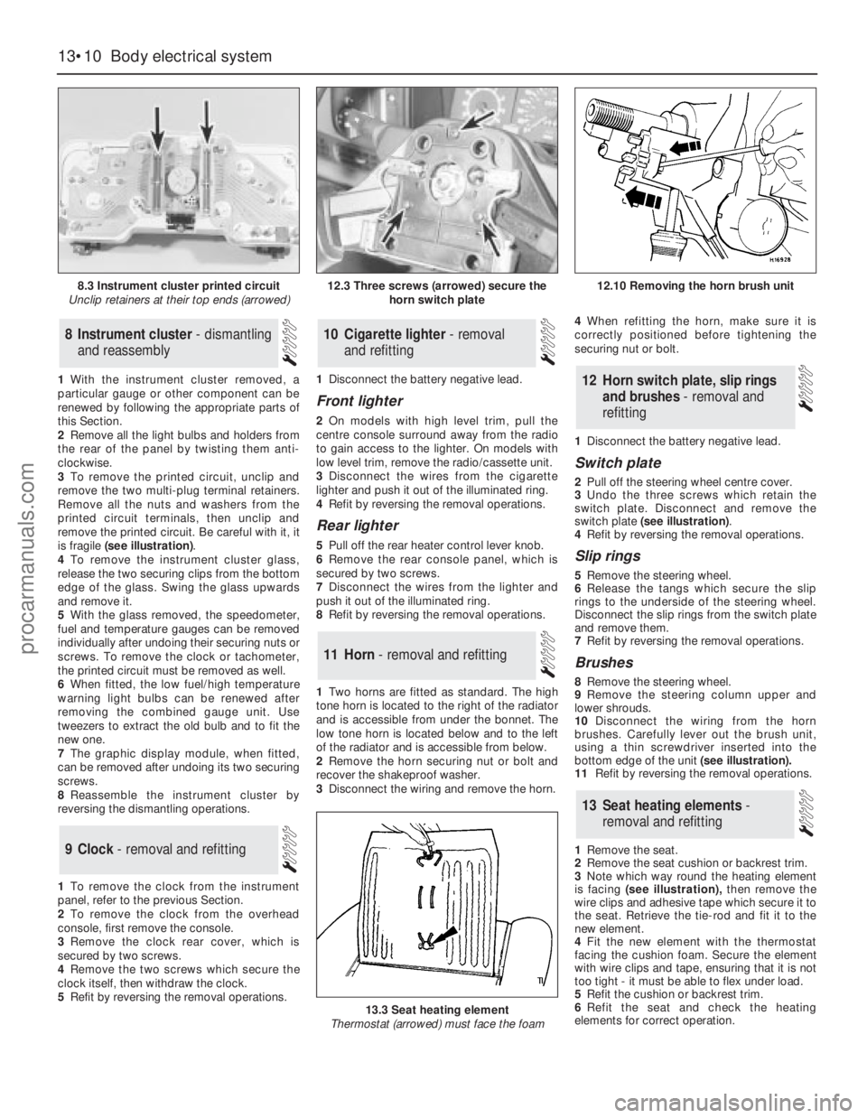
3To remove the printed circuit, unclip and
remove the two multi-plug terminal retainers.
Remove all the nuts and washers from the
printed circuit terminals, then unclip and
remove the printed circuit. Be careful with it, it
is fragile (see illustration).
4To remove the instrument cluster glass,
release the two securing clips from thebottom
edge of the glass. Swing the glass upwards
and remove it.
5With the glass removed, the speedometer,
fuel and temperature gauges can be removed
individually after undoing their securing nuts or
screws. To remove the clock or tachometer,
the printed circuit must be removed as well.
6When fitted, the low fuel/high temperature
warning light bulbs can be renewed after
removing the combined gauge unit. Use
tweezers to extract the old bulb and to fit the
new one.
7The graphic display module, when fitted,
can be removed after undoing its two securing
screws.
8Reassemble the instrument cluster by
reversing the dismantling operations.
1To remove the clock from the instrument
panel, refer to the previous Section.
2To remove the clock from the overhead
console, first remove the console.
3Remove the clock rear cover, which is
secured by two screws.
4Remove the two screws which secure the
clock itself, then withdraw the clock.
5Refit by reversing the removal operations.1Disconnect the battery negative lead.
Front lighter
2On models with high level trim, pull the
centre console surround away from the radio
to gain access to the lighter. On models with
low level trim, remove the radio/cassette unit.
3Disconnect the wires from the cigarette
lighter and push it out of the illuminated ring.
4Refit by reversing the removal operations.
Rear lighter
5Pull off the rear heater control lever knob.
6Remove the rear console panel, which is
secured by two screws.
7Disconnect the wires from the lighter and
push it out of the illuminated ring.
8Refit by reversing the removal operations.
1Two horns are fitted as standard. The high
tone horn is located to the right of the radiator
and is accessible from under the bonnet. The
low tone horn is located below and to the left
of the radiator and is accessible from below.
2Remove the horn securing nut or bolt and
recover the shakeproof washer.
3Disconnect the wiring and remove the horn.4When refitting the horn, make sure it is
correctly positioned before tightening the
securing nut or bolt.
1Disconnect the battery negative lead.
Switch plate
2Pull off the steering wheel centre cover.
3Undo the three screws which retain the
switch plate. Disconnect and remove the
switch plate (see illustration).
4Refit by reversing the removal operations.
Slip rings
5Remove the steering wheel.
6Release the tangs which secure the slip
rings to the underside of the steering wheel.
Disconnect the slip rings from the switch plate
and remove them.
7Refit by reversing the removal operations.
Brushes
8Remove the steering wheel.
9Remove the steering column upper and
lower shrouds.
10Disconnect the wiring from the horn
brushes. Carefully lever out the brush unit,
using a thin screwdriver inserted into the
bottom edge of the unit(see illustration).
11Refit by reversing the removal operations.
1Remove the seat.
2Remove the seat cushion or backrest trim.
3Note which way round the heating element
is facing (see illustration),then remove the
wire clips and adhesive tape which secure it to
the seat. Retrieve the tie-rod and fit it to the
new element.
4Fit the new element with the thermostat
facing the cushion foam. Secure the element
with wire clips and tape, ensuring that it is not
too tight - it must be able to flex under load.
5Refit the cushion or backrest trim.
6Refit the seat and check the heating
elements for correct operation.
13Seat heating elements -
removal and refitting
12Horn switch plate, slip rings
and brushes - removal and
refitting
11Horn - removal and refitting
10Cigarette lighter - removal
and refitting
9Clock - removal and refitting
8Instrument cluster - dismantling
and reassembly
13•10Body electrical system
8.3 Instrument cluster printed circuit
Unclip retainers at their top ends (arrowed)
13.3 Seat heating element
Thermostat (arrowed) must face the foam
12.3 Three screws (arrowed) secure the
horn switch plate12.10 Removing the horn brush unit
procarmanuals.com
Page 196 of 255
17Refit by inserting the switch into the
grommet - use a new grommet if necessary -
and screwing on the retaining ring. Reconnect
the multi-plug and top-up the cooling system.
Washer fluid level switch
18Syphon the fluid out of the washer
reservoir until the level is below the switch.
19Disconnect the switch multi-plug.
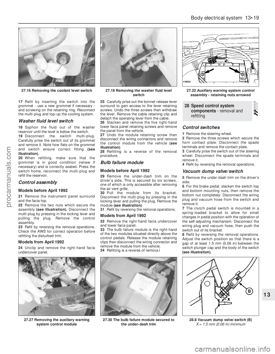
Carefully prise the switch out of its grommet
and remove it. Note how flats on the grommet
and switch ensure correct fitting (see
illustration).
20When refitting, make sure that the
grommet is in good condition (renew if
necessary) and is correctly seated. Press the
switch home, reconnect the multi-plug and
refill the reservoir.
Control assembly
Models before April 1992
21Remove the instrument panel surround
and the facia top.
22Remove the two nuts which secure the
assembly(see illustration).Disconnect the
multi-plug by pressing in the locking lever and
pulling the plug. Remove the control
assembly.
23Refit by reversing the removal operations.
Check the AWS for correct operation before
refitting the disturbed trim.
Models from April 1992
24Unclip and remove the right-hand facia
undercover panel.25Carefully prise out the bonnet release lever
surround to gain access to the lever retaining
screws. Undo the three screws then withdraw
the lever. Remove the cable retaining clip and
detach the operating lever from the cable.
26Slacken and remove the five right-hand
lower facia panel retaining screws and remove
the panel from the vehicle.
27Undo the module retaining screw then
disconnect the wiring connectors and remove
the control module from the vehicle (see
illustration).
28Refitting is a reverse of the removal
procedure.
Bulb failure module
Models before April 1992
29Remove the under-dash trim on the
driver’s side. This is secured by six screws,
one of which is only accessible after removing
the air vent grille.
30Pull the module from its bracket.
Disconnect the multi-plug by pressing in the
locking lever and pulling the plug. Remove the
module (see illustration).
31Refit by reversing the removal operations.
Models from April 1992
32Remove the right-hand facia undercover
and lower facia panel.
33The bulb failure module is the right-hand
of the two modules situated directly above the
control pedals. Release the module retaining
clips then disconnect the wiring connector and
remove the module from the vehicle.
34Refitting is a reverse of remova.l
Control switches
1Remove the steering wheel.
2Remove the three screws which secure the
horn contact plate. Disconnect the spade
terminals and remove the contact plate.
3Carefully prise the switch out of the steering
wheel. Disconnect the spade terminals and
remove it.
4Refit by reversing the removal operations.
Vacuum dump valve/switch
5Remove the under-dash trim on the driver’s
side.
6For the brake pedal, slacken the switch top
and bottom mounting nuts, then remove the
bottom nut completely. Disconnect the wiring
plug and vacuum hose from the switch and
remove it.
7The clutch pedal switch is mounted in a
spring-loaded bracket to allow for small
changes in pedal position with the operation of
the self-adjusting mechanism. Disconnect the
wiring plug and vacuum hose, then push the
switch out of its bracket.
8Refit by reversing the removal operations.
Adjust the switch position so that there is a
gap of at least 1.5 mm (0.06 in) between the
switch plunger cap and the body of the switch
(see illustration).
28Speed control system
components - removal and
refitting
Body electrical system 13•19
13
27.16 Removing the coolant level switch27.19 Removing the washer fluid level
switch27.22 Auxiliary warning system control
assembly - retaining nuts arrowed
27.27 Removing the auxiliary warning
system control module27.30 The bulb failure module secured to
the under-dash trim28.8 Vacuum dump valve/switch (B)
X = 1.5 mm (0.06 in) minimum
procarmanuals.com
Page 197 of 255
Speed control module
Models before April 1992
9Refer to Section 27. The speed control
module shares the same mountings as the
AWS module; the AWS module is larger.
Models from April 1992
10The speed control module fitted to these
models is situated behind the glovebox on the
left-hand side of the facia. To gain access to
the module remove the left-hand facia
undercover panel. The speed control module
is vertically mounted just to the right of the
engine management module. Push the module
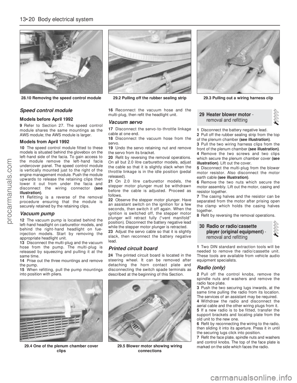
upwards to release the retaining clips then
lower it out from under the facia and
disconnect the wiring connector (see
illustration).
11Refitting is a reverse of the removal
procedure ensuring that the module is
securely retained by the retaining clips.
Vacuum pump
12The vacuum pump is located behind the
left-hand headlight on carburettor models, and
behind the right-hand headlight on fue-
injection models. Start by removing the
appropriate headlight unit.
13Disconnect the multi-plug and the vacuum
hose from the pump. The multi-plug is
released by squeezing and pulling it at the
same time.
14Prise out the three mountings and remove
the pump.
15When refitting, pull the pump mountings
into position with pliers. 16Reconnect the vacuum hose and the
multi-plug, then refit the headlight unit.
Vacuum servo
17Disconnect the servo-to-throttle linkage
cable at one end.
18Disconnect the vacuum hose from the
servo.
19Undo the servo retaining nut and remove
the servo from its bracket.
20Refit by reversing the removal operations.
On all but 2.0 litre carburettor models, adjust
the cable so that it is slightly slack when the
throttle linkage is in the idle position (pedal
released).
21On 2.0 litre carburettor models, the
stepper motor plunger must be withdrawn
before the cable is adjusted. Proceed as
follows.
22Observe the stepper motor plunger. Have
an assistant switch on the ignition for a few
seconds, then switch it off again. When the
ignition is switched off, the stepper motor
plunger will retract fully (“vent manifold”
position). Disconnect the battery negative lead
while the stepper motor plunger is retracted.
23Adjust the servo cable so that it is slightly
slack, then reconnect the battery negative
lead.
Printed circuit board
24The printed circuit board is located in the
steering wheel. It can be removed after
detaching the horn contact plate and
disconnecting the switch spade terminals as
described at the beginning of this Section.1Disconnect the battery negative lead.
2Pull off the rubber sealing strip from the top
of the plenum chamber (see illustration).
3Pull the two wiring harness clips from the
front of the plenum chamber (see illustration).
4Remove the two screws and two clips
which secure the plenum chamber cover (see
illustration). Lift out the cover.
5Disconnect the multi-plug from the blower
motor resistor. Also disconnect the motor
earth cable (see illustration).
6Remove the two nuts which secure the
motor assembly. Lift out the motor, casing and
resistor together.
7The casing halves and the resistor can be
separated from the motor after prising open
the clamp which holds the casing halves
together.
8Refit by reversing the removal operations.
1Two DIN standard extraction tools will be
needed to remove the radio/cassette unit.
These tools are available from vehicle audio
equipment specialists.
Radio (only)
2Pull off the control knobs, remove the
spindle nuts and washers and remove the
radio face plate.
3Push the two securing lugs inwards, at the
same time pulling the radio from its location.
The services of an assistant may be required.
4Withdraw the radio and disconnect the
aerial cable and the other wiring plugs from it.
5If a new radio is to be fitted, transfer the
support brackets and locating plate from the
old unit to the new one.
6Refit by reconnecting the wiring to the radio,
then sliding it into its aperture. Press it in until
the securing lugs click into position.
7Refit the face plate, spindle nuts and washers
and control knobs. The top of the face plate is
marked on the side which faces the radio.
30Radio or radio/cassette
player (original equipment) -
removal and refitting
29Heater blower motor -
removal and refitting
13•20Body electrical system
28.10 Removing the speed control module
29.4 One of the plenum chamber cover
clips29.5 Blower motor showing wiring
connections
29.2 Pulling off the rubber sealing strip29.3 Pulling out a wiring harness clip
procarmanuals.com
Page 200 of 255
The components of the alarm system are a
control module, tripping switches, activating
switches, an alarm horn and a signal buzzer.
The control module is located behind the
facia. It determines whether the alarm is set or
not, monitors the tripping switches and the
ignition circuit, and limits the duration of the
alarm to 30 seconds. This last item is a legal
requirement. The control module also
operates the signal buzzer to tell the driver
that the alarm is set, and controls the activator
delay.
The tripping switches on the doors and
tailgate are the same as those used for “open
door” warnings in the AWS. The bonnet switch
is peculiar to the alarm system.
The activating switches are fitted to the
front door lock barrels, where they are
activated by a lug on the end of the barrel.
They only make contact momentarily as the
lock is operated.
The alarm horn is mounted next to the
battery. Both the horn and its leads are
claimed to be inaccessible without opening
the bonnet. The signal buzzer is also mounted
under the bonnet.
No service, repair or component renewal
procedures have been published for the alarmsystem components on earlier models. Any
problems arising which cannot be dealt with
by component substitution should therefore
be referred to a Ford dealer.
Ultrasonic sensor
1Disconnect the battery negative terminal.
2Prise out the retaining screw trim cap from
the centre of the sensor then slacken and
remove the retaining screws and lower the
sensor away from the headlining,
disconnecting the wiring plug as it becomes
accessible.
3Refitting is the reverse of the removal
procedure.
Anti-theft alarm module (models
from April 1992)
4On these models the alarm module is located
behind the righthand lower facia panel.
5To remove the module, remove the right-
hand facia undercover and lower facia panel.
6The anti-theft alarm module is the left-hand
of the two modules situated directly above the
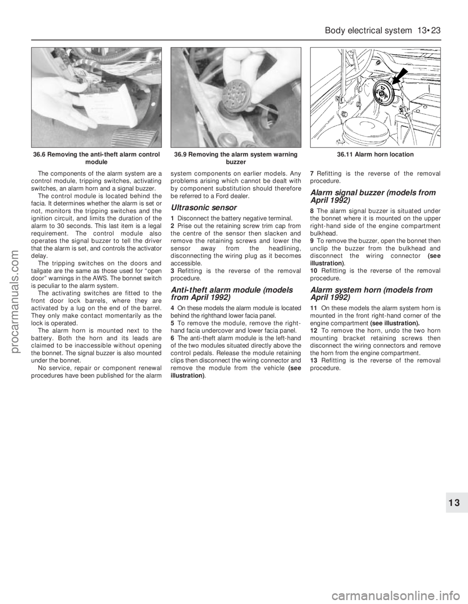
control pedals. Release the module retaining
clips then disconnect the wiring connector and
remove the module from the vehicle (see
illustration).7Refitting is the reverse of the removal
procedure.
Alarm signal buzzer (models from
April 1992)
8The alarm signal buzzer is situated under
the bonnet where it is mounted on the upper
right-hand side of the engine compartment
bulkhead.
9To remove the buzzer, open the bonnet then
unclip the buzzer from the bulkhead and
disconnect the wiring connector (see
illustration).
10Refitting is the reverse of the removal
procedure.
Alarm system horn (models from
April 1992)
11On these models the alarm system horn is
mounted in the front right-hand corner of the
engine compartment (see illustration).
12To remove the horn, undo the two horn
mounting bracket retaining screws then
disconnect the wiring connectors and remove
the horn from the engine compartment.
13Refitting is the reverse of the removal
procedure.
Body electrical system 13•23
13
36.6 Removing the anti-theft alarm control
module36.9 Removing the alarm system warning
buzzer36.11 Alarm horn location
procarmanuals.com
Page 240 of 255
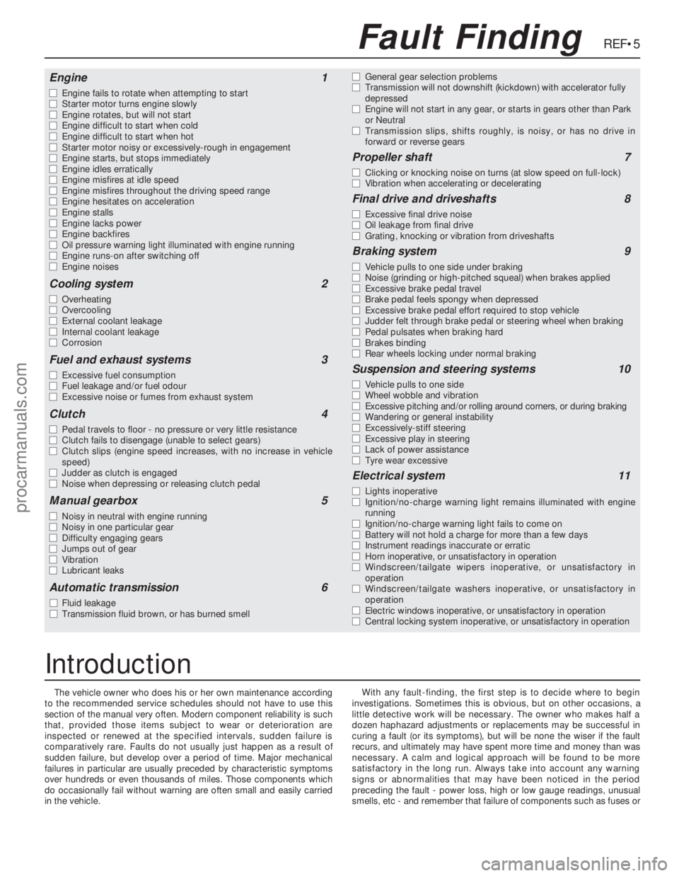
The vehicle owner who does his or her own maintenance according
to the recommended service schedules should not have to use this
section of the manual very often. Modern component reliability is such
that, provided those items subject to wear or deterioration are
inspected or renewed at the specified intervals, sudden failure is
comparatively rare. Faults do not usually just happen as a result of
sudden failure, but develop over a period of time. Major mechanical
failures in particular are usually preceded by characteristic symptoms
over hundreds or even thousands of miles. Those components which
do occasionally fail without warning are often small and easily carried
in the vehicle.With any fault-finding, the first step is to decide where to begin
investigations. Sometimes this is obvious, but on other occasions, a
little detective work will be necessary. The owner who makes half a
dozen haphazard adjustments or replacements may be successful in
curing a fault (or its symptoms), but will be none the wiser if the fault
recurs, and ultimately may have spent more time and money than was
necessary. A calm and logical approach will be found to be more
satisfactory in the long run. Always take into account any warning
signs or abnormalities that may have been noticed in the period
preceding the fault - power loss, high or low gauge readings, unusual
smells, etc - and remember that failure of components such as fuses or
REF•5Fault Finding
Engine1
m mEngine fails to rotate when attempting to start
m mStarter motor turns engine slowly
m mEngine rotates, but will not start
m mEngine difficult to start when cold
m mEngine difficult to start when hot
m mStarter motor noisy or excessively-rough in engagement
m mEngine starts, but stops immediately
m mEngine idles erratically
m mEngine misfires at idle speed
m mEngine misfires throughout the driving speed range
m mEngine hesitates on acceleration
m mEngine stalls
m mEngine lacks power
m mEngine backfires
m mOil pressure warning light illuminated with engine running
m mEngine runs-on after switching off
m mEngine noises
Cooling system2
m
mOverheating
m mOvercooling
m mExternal coolant leakage
m mInternal coolant leakage
m mCorrosion
Fuel and exhaust systems3
m
mExcessive fuel consumption
m mFuel leakage and/or fuel odour
m mExcessive noise or fumes from exhaust system
Clutch4
m
mPedal travels to floor - no pressure or very little resistance
m mClutch fails to disengage (unable to select gears)
m mClutch slips (engine speed increases, with no increase in vehicle
speed)
m mJudder as clutch is engaged
m mNoise when depressing or releasing clutch pedal
Manual gearbox5
m
mNoisy in neutral with engine running
m mNoisy in one particular gear
m mDifficulty engaging gears
m mJumps out of gear
m mVibration
m mLubricant leaks
Automatic transmission6
m
mFluid leakage
m mTransmission fluid brown, or has burned smellm mGeneral gear selection problems
m mTransmission will not downshift (kickdown) with accelerator fully
depressed
m mEngine will not start in any gear, or starts in gears other than Park
or Neutral
m mTransmission slips, shifts roughly, is noisy, or has no drive in
forward or reverse gears
Propeller shaft7
m
mClicking or knocking noise on turns (at slow speed on full-lock)
m mVibration when accelerating or decelerating
Final drive and driveshafts8
m
mExcessive final drive noise
m mOil leakage from final drive
m mGrating, knocking or vibration from driveshafts
Braking system9
m
mVehicle pulls to one side under braking
m mNoise (grinding or high-pitched squeal) when brakes applied
m mExcessive brake pedal travel
m mBrake pedal feels spongy when depressed
m mExcessive brake pedal effort required to stop vehicle
m mJudder felt through brake pedal or steering wheel when braking
m mPedal pulsates when braking hard
m mBrakes binding
m mRear wheels locking under normal braking
Suspension and steering systems10
m
mVehicle pulls to one side
m mWheel wobble and vibration
m mExcessive pitching and/or rolling around corners, or during braking
m mWandering or general instability
m mExcessively-stiff steering
m mExcessive play in steering
m mLack of power assistance
m mTyre wear excessive
Electrical system11
m
mLights inoperative
m mIgnition/no-charge warning light remains illuminated with engine
running
m mIgnition/no-charge warning light fails to come on
m mBattery will not hold a charge for more than a few days
m mInstrument readings inaccurate or erratic
m mHorn inoperative, or unsatisfactory in operation
m mWindscreen/tailgate wipers inoperative, or unsatisfactory in
operation
m mWindscreen/tailgate washers inoperative, or unsatisfactory in
operation
m mElectric windows inoperative, or unsatisfactory in operation
m mCentral locking system inoperative, or unsatisfactory in operation
Introduction
procarmanuals.com
Page 246 of 255
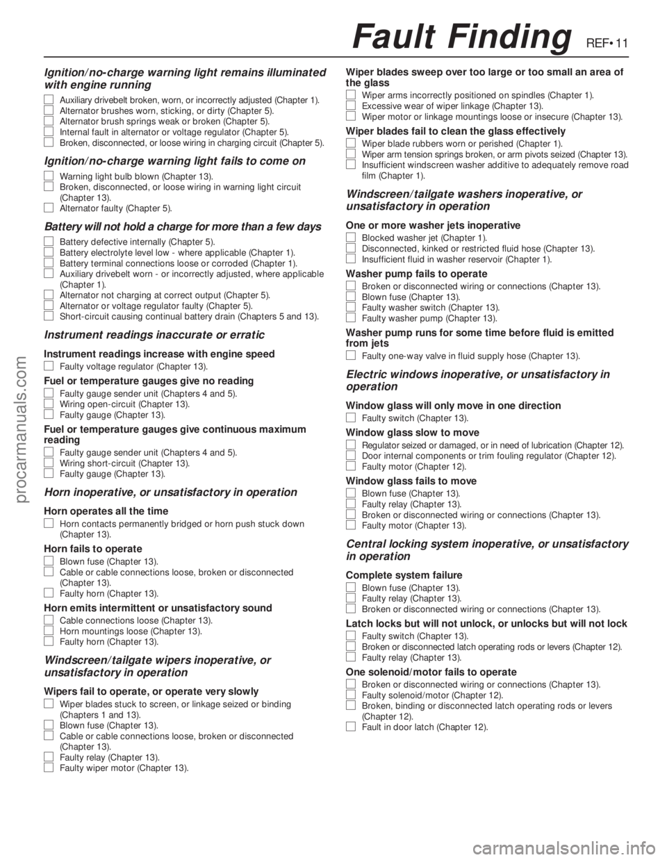
Ignition/no-charge warning light remains illuminated
with engine running
m m
Auxiliary drivebelt broken, worn, or incorrectly adjusted (Chapter 1).m
mAlternator brushes worn, sticking, or dirty (Chapter 5).m
mAlternator brush springs weak or broken (Chapter 5).m
mInternal fault in alternator or voltage regulator (Chapter 5).m
mBroken, disconnected, or loose wiring in charging circuit (Chapter 5).
Ignition/no-charge warning light fails to come on
m m
Warning light bulb blown (Chapter 13).m
mBroken, disconnected, or loose wiring in warning light circuit
(Chapter 13).
m mAlternator faulty (Chapter 5).
Battery will not hold a charge for more than a few days
m m
Battery defective internally (Chapter 5).m
mBattery electrolyte level low - where applicable (Chapter 1).m
mBattery terminal connections loose or corroded (Chapter 1).m
mAuxiliary drivebelt worn - or incorrectly adjusted, where applicable
(Chapter 1).
m mAlternator not charging at correct output (Chapter 5).m
mAlternator or voltage regulator faulty (Chapter 5).m
mShort-circuit causing continual battery drain (Chapters 5 and 13).
Instrument readings inaccurate or erratic
Instrument readings increase with engine speed
m
mFaulty voltage regulator (Chapter 13).
Fuel or temperature gauges give no reading
m
mFaulty gauge sender unit (Chapters 4 and 5).m
mWiring open-circuit (Chapter 13).m
mFaulty gauge (Chapter 13).
Fuel or temperature gauges give continuous maximum
reading
m mFaulty gauge sender unit (Chapters 4 and 5).m
mWiring short-circuit (Chapter 13).m
mFaulty gauge (Chapter 13).
Horn inoperative, or unsatisfactory in operation
Horn operates all the time
m
mHorn contacts permanently bridged or horn push stuck down
(Chapter 13).
Horn fails to operate
m mBlown fuse (Chapter 13).m
mCable or cable connections loose, broken or disconnected
(Chapter 13).
m mFaulty horn (Chapter 13).
Horn emits intermittent or unsatisfactory sound
m
mCable connections loose (Chapter 13).m
mHorn mountings loose (Chapter 13).m
mFaulty horn (Chapter 13).
Windscreen/tailgate wipers inoperative, or
unsatisfactory in operation
Wipers fail to operate, or operate very slowly
m mWiper blades stuck to screen, or linkage seized or binding
(Chapters 1 and 13).
m mBlown fuse (Chapter 13).m
mCable or cable connections loose, broken or disconnected
(Chapter 13).
m mFaulty relay (Chapter 13).m
mFaulty wiper motor (Chapter 13).
Wiper blades sweep over too large or too small an area of
the glass
m mWiper arms incorrectly positioned on spindles (Chapter 1).m
mExcessive wear of wiper linkage (Chapter 13).m
mWiper motor or linkage mountings loose or insecure (Chapter 13).
Wiper blades fail to clean the glass effectively
m
mWiper blade rubbers worn or perished (Chapter 1).m
mWiper arm tension springs broken, or arm pivots seized (Chapter 13).m
mInsufficient windscreen washer additive to adequately remove road
film (Chapter 1).
Windscreen/tailgate washers inoperative, or
unsatisfactory in operation
One or more washer jets inoperative
m mBlocked washer jet (Chapter 1).m
mDisconnected, kinked or restricted fluid hose (Chapter 13).m
mInsufficient fluid in washer reservoir (Chapter 1).
Washer pump fails to operate
m
mBroken or disconnected wiring or connections (Chapter 13).m
mBlown fuse (Chapter 13).m
mFaulty washer switch (Chapter 13).m
mFaulty washer pump (Chapter 13).
Washer pump runs for some time before fluid is emitted
from jets
m mFaulty one-way valve in fluid supply hose (Chapter 13).
Electric windows inoperative, or unsatisfactory in
operation
Window glass will only move in one direction
m mFaulty switch (Chapter 13).
Window glass slow to move
m
mRegulator seized or damaged, or in need of lubrication (Chapter 12).m
mDoor internal components or trim fouling regulator (Chapter 12).m
mFaulty motor (Chapter 12).
Window glass fails to move
m
mBlown fuse (Chapter 13).m
mFaulty relay (Chapter 13).m
mBroken or disconnected wiring or connections (Chapter 13).m
mFaulty motor (Chapter 13).
Central locking system inoperative, or unsatisfactory
in operation
Complete system failure
m mBlown fuse (Chapter 13).m
mFaulty relay (Chapter 13).m
mBroken or disconnected wiring or connections (Chapter 13).
Latch locks but will not unlock, or unlocks but will not lock
m
mFaulty switch (Chapter 13).m
mBroken or disconnected latch operating rods or levers (Chapter 12).m
mFaulty relay (Chapter 13).
One solenoid/motor fails to operate
m
mBroken or disconnected wiring or connections (Chapter 13).m
mFaulty solenoid/motor (Chapter 12).m
mBroken, binding or disconnected latch operating rods or levers
(Chapter 12).
m mFault in door latch (Chapter 12).
REF•11Fault Finding
procarmanuals.com
Page 252 of 255
A
ABS module - 10•11
Accelerator pump diaphragm renewal - 4•12
Accessory shops - 0•8
Acknowledgements - 0•4
Aerial pre-amplifier - 13•22
Air bags - 0•5
Air charge temperature sensor - 5•12
Air cleaner - 1•16, 4•4
Air conditioner - 1•14, 1•15, 3•2, 3•9
Air temperature sensor - 13•18
Alarm signal buzzer - 13•23
Alarm system horn - 13•23
Alternator - 3•7, 5•4
Anti-roll bar - 11•9, 11•12
Anti-theft alarm - 13•22, 13•23
Antifreeze mixture - 3•2
Asbestos - 0•5
Ashtray light - 13•8
Automatic choke - 1•16, 4•10, 4•12
Automatic transmission- 1•11, 1•15, 2B•6,
2B•7, 7B•1et seq, REF•8
Automatic transmission brake band
adjustment - 1•19
Automatic transmission selector light - 13•9
Auxiliary drivebelt - 1•12
Auxiliary driving light - 13•4, 13•6
Auxiliary shaft - 2A•9, 2A•14, 2A•16
Auxiliary warning system components - 13•18
B
Backrests - 12•19, 12•18
Battery - 0•5, 1•8, 1•13, 5•3, 5•4
Battery will not hold a charge for more than
a few days - REF•11
Bleeding the brakes - 10•3
Bleeding the power steering - 11•3
Body corrosion - 0•14
Body damage - 12•2, 12•4
Body electrical system- 13•1et seq
Bodywork and fittings- 12•1et seq
Bodywork repairs - 12•3
Bonnet - 12•4, 12•9
Bonnet release cable - 12•6
Booster battery (jump) starting - 0•10
Boot lid - 12•5
Boot lid lock barrel - 12•7
Brake band adjustment - 1•19, 7B•3
Brake fluid - 1•7, 1•19
Brake hydraulic system - 10•3
Brake pedal effort high to stop vehicle - REF•9
Brake pedal feels spongy when depressed
- REF•9
Brake pedal pulsates when braking hard -
REF•10
Brake pedal travel excessive - REF•9
Brake pipe and hoses - 1•15, 10•10
Brakes binding - REF•10
Braking system- 0•13, 10•1et seq, REF•9
Bulb failure module - 13•19
Bulbs - 13•4, 13•7
Bumper - 12•10, 12•11
Burning - 0•5
C
Cables - 3•8, 4•7, 6•3, 7B•3, 10•11
Caliper - 10•5, 10•6
Camshaft - 2A•7, 2A•14, 2A•17, 2B•14,
2C•12, 2C•13, 2C•15
Camshaft drivebelt - 1•20
Capacities - 1•3
Carbon canister - 4•23
Carburettor stepper motor - 5•10
Catalytic converter - 4•4
Central locking motor - 13•13
Central locking system inoperative, or
unsatisfactory in operation - REF•11
Centre console - 12•15
Cigarette lighter - 13•10
Clock - 13•9, 13•10
Clutch- 6•1et seq, REF•8
Clutch fails to disengage (unable to select
gears) - REF•8
Clutch pedal travels to floor - REF•8
Clutch release bearing and arm - 6•4
Clutch slips (engine speed increases, with
no increase in vehicle speed) - REF•8
CO emissions (mixture) - 0•14
Compliance bushes - 11•9
Compression test - 2A•20, 2B•18, 2C•21
Compressor drivebelt - 3•9
Computer module and bulb - 13•18
Condenser fan and motor - 3•10
Connecting rods - 2A•11, 2A•13, 2A•15,
2B•17, 2C•12, 2C•14, 2C•16
Console light - 13•9
Contents - 0•2
Control assembly - 13•19
Control module - 10•13
Control switches - 13•19
Control units - 13•13
Conversion factors - REF•16
Coolant - 1•6, 1•20
Coolant hoses - 2C•7
Coolant leakage - REF•7
Coolant level switch - 13•18
Coolant temperature sensor - 5•10
Cooling, heating and ventilation systems-
3•1 et seq, REF•7
Corrosion - REF•7
Courtesy light - 13•7
Crankcase ventilation system - 1•19,
2A•12, 2B•3, 2C•15
Crankshaft and bearings - 2A•11, 2A•12,
2A•15, 2B•17, 2B•18, 2C•12, 2C•14,
2C•15
Crankshaft oil seals - 2A•10, 2B•15, 2C•12
Crankshaft speed/position sensor - 5•11
Crossmember insulator - 11•12
Crushing - 0•5
Cushion - 12•18
Cylinder block and bores - 2A•13
Cylinder bores - 2C•14
Cylinder head - 2A•6, 2A•8, 2A•14, 2A•17,
2B•10, 2B•11, 2B•14, 2C•8, 2C•13,
2C•19
D
De-ice thermostat - 3•10
Decarbonising - 2A•14
Dents in bodywork - 12•2
Direction indicator - 13•5, 13•11
Discs - 10•3, 10•4, 10•8
Distributor - 5•5
Door exterior handle - 12•6
Door interior trim panel - 12•7
Door latch assembly - 12•6
Door lights - 13•7
Door lock barrel - 12•6
Door pillar switch - 13•12
Door speakers - 13•21
Door striker plate - 12•6
Door switch - 13•18
Door weatherstrip - 12•7
Door window - 12•8, 12•9
Doors - 0•12, 12•4, 12•7, 12•8, 12•9, 12•10
Downshift mechanism - 7B•3
Drivebelts - 1•12, 1•20, 3•7, 3•9, 11•6
Driveshaft - 1•15, 9•3
Drivetrain - 1•16
E
Earth fault - 13•4
EEC IV module - 5•9
Electric shock - 0•5
Electric windows inoperative, or
unsatisfactory in operation - REF•11
Electrical system - 0•12, 1•8, REF•10
Electronic ignition systems - 5•3
Engine- 2A•1 et seq, 2B•1 et seq, 2C•1 et
seq, REF•6
Engine backfires - REF•7
Engine bay light - 13•8
Engine difficult to start - REF•6
Engine dismantling - 2B•8
Engine electrical systems- 5•1et seq
Engine fails to rotate when attempting to
start - REF•6
Engine hesitates on acceleration - REF•7
Engine idles erratically - REF•6
Engine lacks power - REF•7
Engine management control module - 5•9
Engine management system relays - 5•11
Engine misfires - REF•6, REF•7
Engine mountings - 2A•11, 2B•8, 2C•12
Engine oil and filter - 1•6, 1•9
Engine rotates, but will not start - REF•6
Engine runs-on after switching off - REF•7
Engine stalls - REF•7
Engine starts, but stops immediately -
REF•6
Engine will not start in any gear, or starts in
gears other than Park or Neutral -
REF•9
Entertainment console - 13•22
Environmental considerations - REF•4
ESC II module - 5•3, 5•9
Exhaust emission checks - 0•14
Exhaust gas oxygen (HEGO) sensor - 4•22
Exhaust manifold(s) - 4•21
Exhaust system - 0•13, 1•10, 4•22
Expansion tank - 3•7
IND•1Index
Note: References throughout this index are in the form - “Chapter number” • “page number”
procarmanuals.com
Page 253 of 255
IND•2
F
Facia panels and trim - 12•12
Fast idle speed adjustment - 4•13
Fault finding- REF•5et seq
Fault-finding - electrical system - 5•3, 13•3
Final drive and driveshafts- 1•15, 9•1et
seq, 11•10, REF•9
Fire - 0•5
Flasher switch and unit - 13•11
Fluid leakage - REF•8
Fluid level checks - 1•6
Flywheel ring gear - 2A•14, 2C•15
Flywheel/driveplate - 2A•9, 2A•16, 2B•15,
2C•11, 2C•17
Foglight - 13•5,13•13
Footbrake - 0•11, 0•12
Footwell lights - 13•8
Fuel and exhaust systems- 0•14, 4•1et seq,
REF•8
Fuel computer components - 13•17
Fuel consumption high - REF•8
Fuel filler lock barrel - 12•7
Fuel filler switch - 13•18
Fuel filter - 1•19, 4•14
Fuel flow sensor - 13•18
Fuel gauge gives false reading - REF•11
Fuel odour - REF•8
Fuel pressure regulator - 4•18
Fuel temperature sensor - 5•12
Fuel trap (carburettor models) - 5•9
Fume or gas intoxication - 0•5
Fumes from exhaust system - REF•8
Fuses - 13•13
G
G (gravity) switch - 10•14
Gaskets - REF•4
Gear linkage - 7A•4
Gear selection problems - REF•8, REF•9
Glossary of technical terms - REF•12
Glovebox light - 13•8
Graphic display module - 13•18
Graphic equaliser - 13•21
Grille - 12•9
H
Handbrake “ON” switch - 13•12
Handbrake - 0•11, 10•11
Handles - 12•6
Hazard warning switch - 13•9, 13•13
HC emissions - 0•14
Headlight - 13•4, 13•6, 13•7, 13•11
Headlining - 12•11
Headphone relay - 13•22
Heated rear window switch - 13•13
Heated seat control switches - 13•13
Heater assembly - 3•7, 3•8, 3•9, 3•10,
13•11, 13•20
High frequency units - 13•22
High pressure hose - 10•10
Hinges - 1•12
Horn - 13•10
Horn emits intermittent or unsatisfactory
sound - REF•11Horn fails to operate - REF•11
Horn inoperative, or unsatisfactory in
operation - REF•11
Horn operates all the time - REF•11
Horn switch plate, slip rings and brushes -
13•10
HT leads - 5•5
HT voltage - 5•3
Hub - 11•11
Hydraulic system seals and hoses - 1•19
Hydraulic unit - 10•8, 10•9, 10•10
Hydrofluoric acid - 0•5
I
Idle mixture - 1•10
Idle speed - 1•10, 4•7, 4•9, 4•11, 4•14, 5•11
Idle speed control valve - 4•15
Idle speed linkage - 1•15
Ignition coil - 5•9
Ignition module - 5•8
Ignition system - 1•17
Ignition timing - 5•7, 5•11
Ignition/no-charge warning light fails to
come on - REF•11
Ignition/no-charge warning light remains
illuminated with engine running - REF•11
Ignition/starter switch - 13•11
Inlet manifold - 1•14, 4•19
Instrument cluster - 13•9, 13•10
Instrument illumination dimmer switch - 13•11
Instrument panel lights - 13•8
Instrument readings inaccurate or erratic -
REF•11
Instruments and electrical equipment - 1•16
Intensive maintenance - 1•6
Interior lights - 13•7
Introduction to the Ford Granada - 0•4
J
Jacking - 0•6
Joint mating faces - REF•4
Joystick fader control - 13•22
Jump starting - 0•10
Jumps out of gear - REF•8
L
Latch locks but will not unlock, or unlocks
but will not lock - REF•11
Leaks - 0•8, 1•10
Lighter - 13•10
Lighting master switch - 13•11
Lights - 13•4, 13•6
Lights inoperative - REF•10
Locknuts, locktabs and washers - REF•4
Locks - 1•12, 12•6, 12•7
Loudspeakers - 13•21, 13•22
Low pressure hose - 10•10
Lower arm - 11•9, 11•12
Lubricant leaks - REF•8
Lubricants and fluids - 1•2
Luggage area light - 13•8
M
Main bearings - 2A•11, 2A•15, 2B•17,
2C•12, 2C•15
Maintenance - bodywork and underframe -
12•1
Maintenance - upholstery and carpets -
12•2
Manifold absolute pressure (MAP) sensor -
5•12
Manifold heater - 5•11
Manual gearbox- 1•11, 2B•6, 2B•7, 7A•1et
seq, REF•8
Manual steering - 11•3
Master cylinder - 10•12
Mirror - 0•11, 12•12, 13•11
Mixture adjustment potentiometer - 4•19
Mixture adjustments - 4•7, 4•9, 4•11, 4•14
Motifs and emblems - 12•10
Motor factors - 0•9
Mountings - 2A•11, 2B•8, 2C•12
N
Needle valve and float - 4•11
Number plate light - 13•5
O
Oil - 1•6, 1•9
Oil filler cap - 1•10
Oil filter - 1•9, 2A•11
Oil leakage from final drive - REF•9
Oil pressure warning light illuminated with
engine running - REF•7
Oil pressure warning switch - 13•12
Oil pump - 2A•10, 2A•12, 2A•16, 2B•16,
2B•17, 2C•11, 2C•14, 2C•17
Oil seals - 2A•10, 2B•15, 2C•12, 9•2, 9•3,
REF•4
On load voltage check - 5•5
Open-circuit - 13•3
Overcooling - REF•7
Overhead console - 12•17
Overheating - REF•7
P
Pads - 1•10, 10•4, 10•5
Parcel shelf - 12•19
Parking light - 13•4
Pedal Travel Sensor (PTS) - 10•14
Pedals - 6•2, 4•6, 10•8
Pierburg 2V carburettor - 4•7, 4•9
Pistons and connecting rods - 2A•11, 2A•13,
2A•15, 2B•17, 2C•12, 2C•14, 2C•16
Pitching and/or rolling around corners, or
during braking - REF•10
Plastic components - 12•3
Poisonous or irrirant substances - 0•5
Power steering - 1•16, 11•3, 11•4, 11•6
Power valve diaphragm - 4•12
Pre-ignition (pinking) or knocking during
acceleration or under load - REF•7
Printed circuit board - 13•20
Propeller shaft- 8•1et seq, REF•9
Pushrods - 2C•13
Index
procarmanuals.com