Page 13 of 20

POWER STEERING GEAR AND LINKAGE
inspection and Ac
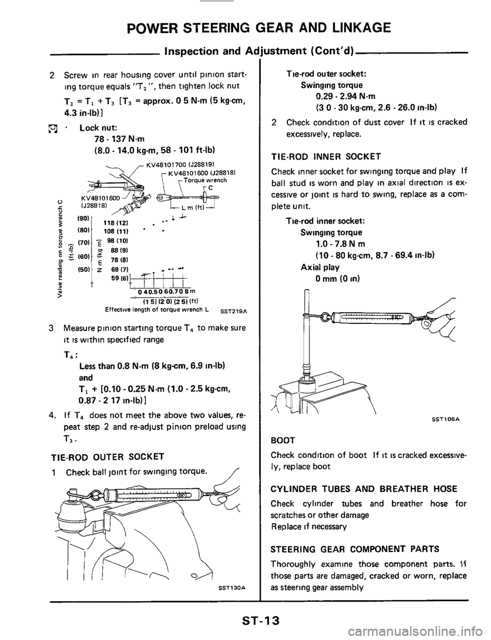
2 Screw in rear housing cover until pinion start-
ing torque equals "T,
", then tighten lock nut
T, =TI
+ T3 [T3 = approx. 0 5 N.m (5 kg-cm,
4.3 in-lb)]
pj . Locknut:
78.137 Nm
(8.0 - 14.0 kgrn, 58 - 101 ft-lb)
KV48101700 lJ288191 KV48101690 lJ28818)
1501 2 69 171 _. -.
? 1 59(61!* T %40.50 60.70 8 m - 9
5 4, I1 51 12 01 (2 51 lft)
Effective length of torque wrench L SST219A
Measure pinion starting torque T4 to make sure
it is within specified range
T4
:
3
Less than 0.8 N.m (8 kgcm, 6.9 in-lb)
and
TI
+ [0.10 - 0.25 Nm (1.0.2.5 kg-cm,
0.87.2 17 in-lb)]
4. If T, does not meet the above two values, re-
peat step
2 and re-adjust pinion preload using
T3.
TIE-ROD OUTER SOCKET
1 Check ball joint for swinging torque. /
SST130A
ustment (Cont'd)
Tie-rod outer socket:
Swinging toque
0.29.2.94 Nm
(3
0 - 30 kg-cm, 2.6 - 26.0 in-lb)
2 Check condition of dust cover If it is cracked
excessively, replace.
TIE-ROD INNER SOCKET
Check inner socket for swinging torque and play If
ball stud
is worn and play in axial direction IS ex-
cessive or joint
is hard to swing, replace as a com-
plete unit.
Tie-rod inner socket:
Swinging toque
1.0 - 7.8 N m
(10 - 80 kg-cm, 8.7 - 69.4 in-lb)
0 mm (0 in)
Axial play
n
it- * SSTl 06A
BOOT
Check condition of boot
If it is cracked excessive-
ly, replace boot
CYLINDER TUBES AND BREATHER HOSE
Check cylinder tubes and breather hose for
scratches or other damage
Replace if necessary
STEERING GEAR COMPONENT PARTS
Thoroughly examine those component parts.
If
those parts are damaged, cracked or worn, replace
as steering gear assembly
ST-1 3
Page 14 of 20
![NISSAN 300ZX 1984 Z31 Steering System Workshop Manual POWER STEERING OIL PUMP
Connector Ispool cover1 Flexible hose
69-78
38.52 mi70-8051 1 A Washe2 Connector bolt
7 . I 0 9- 12 (09.12.65 -871 13 9.5 3,28 - 381
s,,rr,nn ",no.... I
36-51] --I ..I NISSAN 300ZX 1984 Z31 Steering System Workshop Manual POWER STEERING OIL PUMP
Connector Ispool cover1 Flexible hose
69-78
38.52 mi70-8051 1 A Washe2 Connector bolt
7 . I 0 9- 12 (09.12.65 -871 13 9.5 3,28 - 381
s,,rr,nn ",no.... I
36-51] --I ..I](/manual-img/5/578/w960_578-13.png)
POWER STEERING OIL PUMP
Connector Ispool cover1 Flexible hose
69-78
38.52 mi7'0-80'51 1 A Washe2 Connector bolt
7 . I 0 9- 12 (09.12.65 -871 13 9.5 3,28 - 381
s,,rr,nn ",no.... I
36-51] --I ..I.. r,r_
re switch (Non-turbocharged model)
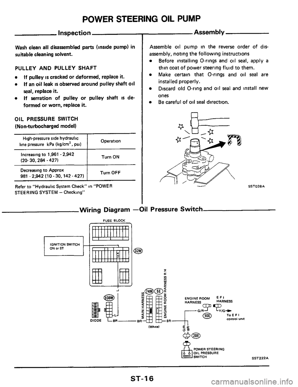
Htgh-pressure ride
hydraultc
line pressure
1,961
- 2,942 kPa
(20.30 kg/cm' ,
Decreasing to aPProx
Turn ON
981 -2,942 kPa
(10 - 30 kg/cm' ,
142-427~511 1
42 I3 2 -43.23- 31)
L Pulley shaft (When assembling pulley shaft. be careful
not to damage oil seal lip1 seal
am
(41 31 -42 13.2 - 4.3, 23 - 311 (41 N m (kg-m. ft-lb)
fl Lubricatzon points (with automatic transmission fluid "Dexron Type") @ ~onotreu~
- Pre-disassembly Inspection
The power steering oil pump should be disassem-
bled only
d any of the following conditions are
ObSWVed.
Oil leak at the following points
SST126A
Deformed or damaged pulley
SST220A
Oil Pump Installation
mounting bracket
steering pump
(41 N m (kgm, ft-lbl
SST221A
m16-21 (1.6-21,
12.15)
After installing oil pump, adjust belt tension.
Refer to MA section.
ST-1 4
Page 15 of 20
POWER STEERING OIL PUMP
Diassernbl y
CAUTION:
a The parts which can be disassembled are strict-
ly limited, and never disassemble other parts
than the specified ones.
Disassembly should be performed in
a place as
clean as possible.
Do not use a rag. Be sure to use nylon or paper
cloth.
When disassembling and reassembling, do not
allow any foreign material to enter
or contact
any parts.
a
a
a
1 Make matching marks.
Matchmg marks 4 SSTl27A
2 Remove rear cover
3
CAUTION :
When removing cam case, be sure that the vane
does not come
off the rotor.
Remove O-rings from cam case.
SSTO32A ,
4
a
Remove snap ring, then draw pulley shaft out
Be careful not
to drop pulley shaft.
SST033A
5. Install cam case and rear cover, then remove 011
seal.
Be careful not to damage casing.
0
f
SST034A
6. Remove joint.
0 Be careful not to drop spool.
L spool
SSTOJSA
7. Remove suction pipe, then remove O-ring
ST-1 5
Page 16 of 20

POWER STEERlNG OIL PUMP
Inspection
Wash clean all disassembled parts (inside pump) in
suitable cleaning solvent.
PULLEY AND PULLEY SHAFT
0
0
If pulley is cracked or deformed, replace it.
If an oil leak IS observed around pulley shaft oil
seal, replace it.
If serration of pulley or pulley shaft IS de-
formed
or worn, replace it.
0
OIL PRESSURE SWITCH
(Non-turbocharged model)
Operation High-pressure side hydraulic
line pressure kPa (kglcm', psi) ~~
I Turn ON Increasing to 1,961 - 2,942
(20- 30,284 ~ 4271
Turn OFF Decreasing to Approx
981 .2,942 (10 - 30,142 - 427)
Refer to "Hydraulic
System Check" in "POWER
STEERING SYSTEM
- Checking"
Assembly
Assemble 011 pump in the reverse order of dts-
assembly, noting the following instructions
Before installing O-rings and oil seal, apply a
thin coat of power steering fluid to them.
Make certain that O-rings and oil
seal are
installed properly.
Discard old O-ring and oil
seal and install new
ones Be careful of
oil seal direction.
Wiring Diagram -Oil Pressure Switch
FUSE BLOCK
IGNITION SWITCH
I a
Y
Ln v)
E
ENGINE ROOM E I R HARNESS HARNESS
IWhnsl d'
POWER STEERING OIL PRESSURE
SST222A
ST-1 6
Page 17 of 20

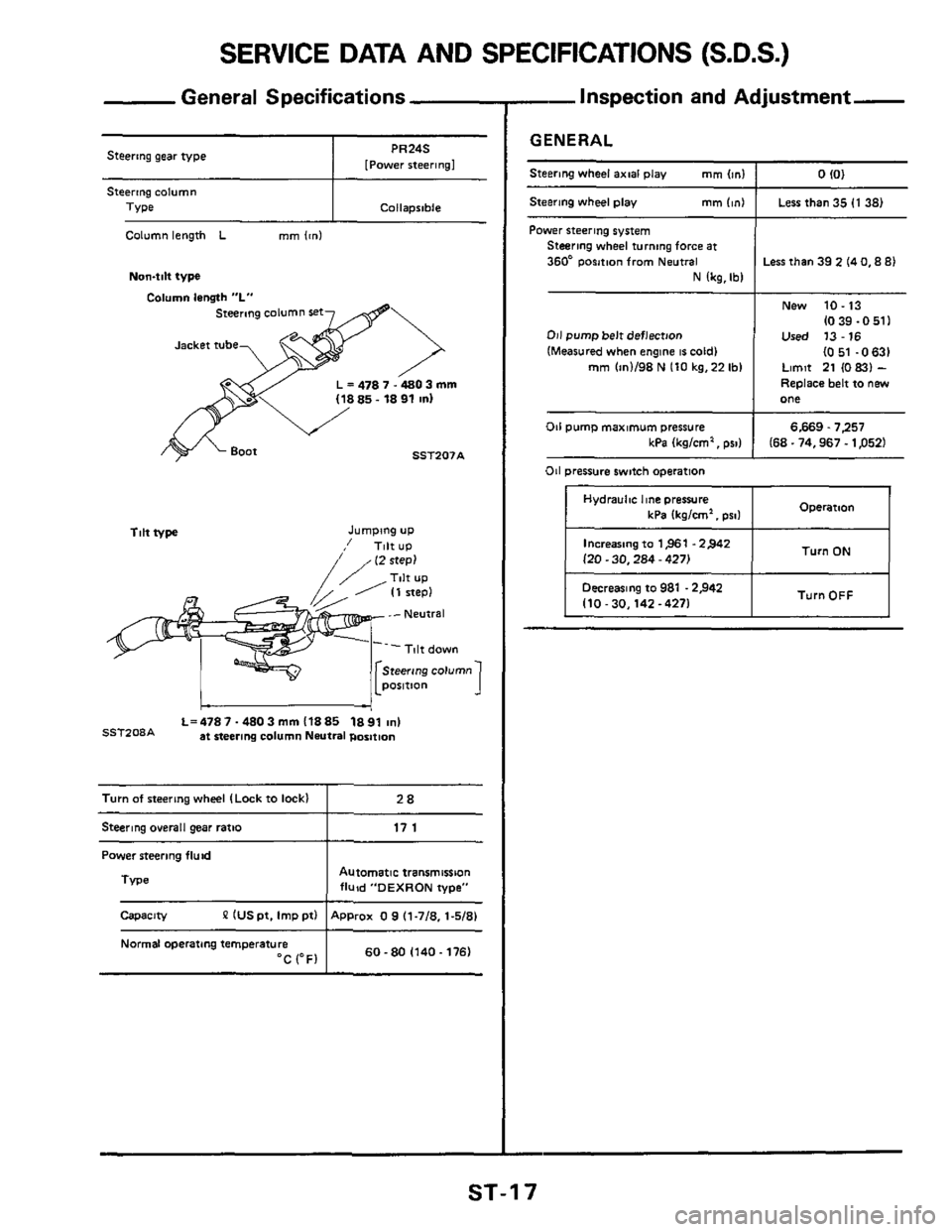
SERVICE DATA AND SPECIFICATIONS (S.D.S.)
Turn of steering wheel (Lock to lock1
General Specifications
28
Steering gear type I [Power PR24S rteerlngl
I Collapsible
Column length L mm lcnl
Non4ilt type
Column lensth "L"
steermg column set
L = 478 7.4803 mm
SST207A
Tilt type Jumping UP
,' Tilt UP
L=4787-4803mml1885 1891 ~nl SSTZ08A at steering column Neutral position
Steering o~erall gear ratio I 17 1
Power steering fluid
Automatic transmission fluid "DEXRON type"
P IUS pt. Imp ptl ApProx 0 9 (1-718. 1-5/81
TVpe 1
Capacity
Normal operating temperature 60-80 (140.1761 "C (OF1
-Inspection and Adjustment-
GENERAL
Steering wheel axial play mm Im1 I 0 IO1
Steering wheel play mm (in1 I Less than 35 (1 38)
Power steering system Steering wheel turning force at
360* Position from Neutral
N lkg,Ibl
011 pump belt deflection
(Measured when engine 16 cold1 mm (in1198 N 110 kg.22 Ibl
Less than 39 2 14 0,8 81
New 10.13
(0 39.0 511 Used 13-16
I051 -0631 Limit 21 (0 831 -
Replace belt to new one
6.669.7257 kPa Ikglcm', PSI) I 168.74,967.1 p521
011 pump maximum pressure
011 pressure switch operation
Hydraulnc he pressure Operation kPa 1kglcm'. pro1 I
Increasing to 1,961 .2>42
l20.30,284 - 4271 Turn ON I
I TurnOFF I Decreasing to 981 .2,942 110-30.142-4271 I
ST-1 7
Page 20 of 20
SPECIAL SERVICE TOOLS
Tool number
(Kent-Moore
No )
ST27 180001
1525726)
HT72520000
(J25730-A)
ST27091000 lJ26357)
KV48101600
(J28818)
KV48101700
(528819)
KV48101800
(528820)
KV48102100
(J28817)
KV48103100
(534264)
Tool name
Unit application
X
Steering wheel puller
a join remover
Rear housing lock nut
wrench
Rear cover wrench
e X
I
Cylinder lock nut
wrench
X
I
X
Power steering stand
X
Rack packing installer
ST-20