Page 1 of 20
STEERING SYSTEM
I---
SECTION ST
CONTENTS
STEERING SYSTEM . . . ... ..
STEERING COLUMN . . . .... ..
POWER STEERING SYSTEM -Checking - . ..
POWER STEERING GEAR AND LINKAGE
POWER STEERING
OIL PUMP . .. ... ..
SERVICE DATA AND SPECIFICATIONS (S D S ) . . . . . . . .
SPECIAL SERVICE TOOLS . .. .. ..
Refer to section MA for:
CHECKING WHEEL ALIGNMENT
Toe-in
Front wheel turning angle
BASIC MECHANICAL SYSTEM
Checking drive belts
. ST- 2
ST- 4
.. ST- 6
. . ST- 8
ST-14
. .. .. ST-17
. . . ST-20
Page 2 of 20
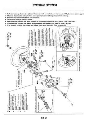
STEERING SYSTEM
a Fully turn steering wheel to the right and disconnect whole hydraulic line to steering gear ASSY. then remove steering gear
Whenever dirconnecitng hydraulic lines, cover openings to prevent foreign material from entering
a Be careful not to damage hydraulic line connection
a Do not reuse O-ring in hydraulic system.
a When conecting hydraulic line, apply a coat of oil (Automatic transmission fluid "Dexron Type") to O-rings
If disconnecting hydraulic line. always perform leak test and bleed air from line after filling it with oil
a After properly installing steering gear and linkage, check wheel alignment Refer to section MA
ST-2
Page 3 of 20
Page 4 of 20
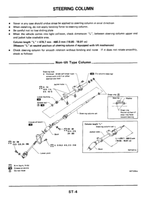
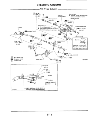
STEERING COLUMN
Never in any case should undue stress be applied to steering column in axial direction
When installing, do not apply bending force to steering column.
Be careful not to lose sliding plate
When the vehicle comes into light collision, check dimension "L", between steering column upper end
and jacket tube crashable area.
Column length "L" = 478.7 mm - 480.3 mm (18.85 - 18.91 in)
(Measure "L"at neutral position
of steering column if equipped wlth tilt mechanism)
Check steering column for smooth rotation without binding and nom
check
as follows
If it does not rotate smoothly,
Non-tilt Type Column
R
Steering lock Removal Break self-shear type ITo column bearmgl
screws with B drdl or other approprme too1
Lower bushing
Round surface Of Steering column set
teermg column set
- 478 7. a803 mrn
32-38
3.5 10.3.0 5, 2 2- 3 61
N rn lkgm, ft-lbl
Grease-UP Wonts @ DO notreuse SSTZOSA
ST-4
Page 5 of 20
STEERING COLUMN
Tilt Type Column
Steering lock Steering Removal Break relf-shear type column clamp
(ql32-38
screwrwith a drill or other 24.281 l3 - g,+
Jacket upper tube
=(Inride of boots1
p? N m (kg-m,ft-lbl (0 9.14.6 5.10 11
a DO not reuse Grease UP points
22-361 v
1
steenng column
i
L = 478 7 - 480 3 mm I18 85 - 18 91 ml at steermg column Neutral position S S T 2 0 8 A
Bearing c7
4
snap rtng --t
Rounded surface of snap rmg facer toward bearing
SST206A
ST-5
Page 6 of 20

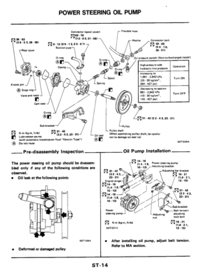
POWER STEERING SYSTEM -Checking
Fluid Level Check
Check the fluid level when the fluid IS cold.
Refer to MA section
Power Steering Pump
Belt Tension
Refer to MA section
Fluid Leakage Check
1 Run engine at idle speed or 1,000 rpm
Make sure temperature of fluid
in tank rises to
60 to 80°C (140 to 176°F).
2 Turn steering wheel to right-to-left several
times
3 Hold steering wheel at each "lock" position for
five seconds
and carefully check for fluid
leakage
CAUTION :
0 Do not hold steering wheel at "lock" position
for more than 15 seconds at a time.
0 If fluid leaks at connectors, replace O-ring (if
equipped) Do not overtighten connector as
this can damage O-ring and connector.
- Bleeding Hydraulic System -
1. Raise front end of vehicle until wheels clear
ground
2 While adding fluid, quickly turn steering wheel
fully to right and
left and lightly touch steering
stoppers.
Repeat steering wheel operation until fluid
level no
longer decreases
Repeat step 2 above
3. Start engine.
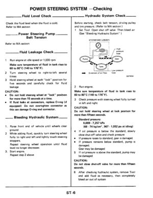
Hydraulic System Check
Before starting, check belt tension, driving pulley
and tire pressure. (Refer to MA section )
1 Set Tool Open shut off valve Then bled air
(See "Bleeding Hydraulic System" )
ST27091000 lJ263571
L 1 ow pressure
& Direction of 011 flow hose
ET834
2 Run engine.
Make sure temperature of fluid in tank rises to
60 to 80°C
(140 to 176°F).
3 Check pressure with steering wheel fully turned
in left and right
CAUTION:
Do not hold steering wheel at lock position for
more than fifteen seconds.
Standard pressure:
6,669 - 7,257 kPa
(68
- 74 kglcm' ,967 - 1,052 psi at idling)
4
0
0
If oil pressure is below the standard, slowly
close shut-off valve and check pressure
If pressure raises to standard, gear is damaged
If pressure remains below standard, pump
IS
damaged.
Gear may be damaged
If oil pressure is above the standard, pump may
be damaged 5
CAUTION:
Do not close shutoff valve for more than fifteen
seconds.
6 After checking hydraulic system, remove Tool
and add fluid as necessary, then completely
bleed
air out of system
ST-6
Page 7 of 20

POWER STEERING SYSTEM -Checking
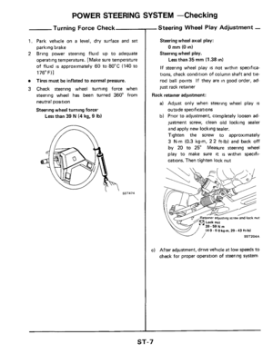
Turning Force Check
1. Park vehicle on a level, dry surface and set
parking brake
2 Bring power steering fluid up to adequate
operating temperature. [Make sure temperature
of fluid
is approximately 60 to 80°C (140 to
176"F)l
Tires must be inflated to normal pressure.
3 Check steering wheel turning force when
steering wheel has been turned 360" from
neutral position
Steering wheel turning force.
Less than 39 N (4 kg, 9 Ib)
SST474
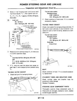
-Steering Wheel Play Adjustment -
Steering wheel axial play:
0 mm (0 in)
Steering wheel play.
Less than 35 mm (1.38 in)
If steering wheel play is not within specifica-
tions, check condition of column shaft and
tie-
rod ball points If they are in good order, ad-
just rack retainer
Rack retainer adjustment:
a) Adjust only when steering wheel play is
outside specifications
b) Prior to adjustment, completely loosen ad-
justment screw, clean old locking sealer
and apply new locking sealer.
Tighten the screw to approximately
3 N.m (0.3 kg-m, 22 ft-lb) and back off
by
20 to 25" Measure steering wheel
play to make sure
it is within specifi-
cations. Then tighten lock nut
"1
kg-m. 29 - 43 ft-lbl
c) After adjustment, drive vehicle at low speeds to
check for proper operation
of steering system
ST-7
Page 8 of 20

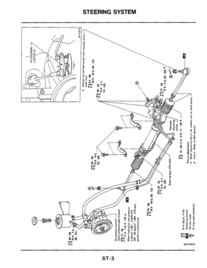
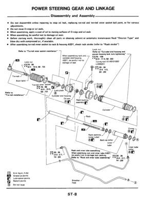
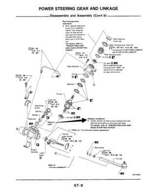
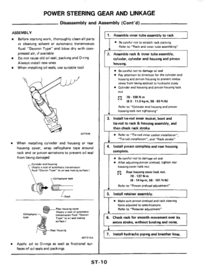
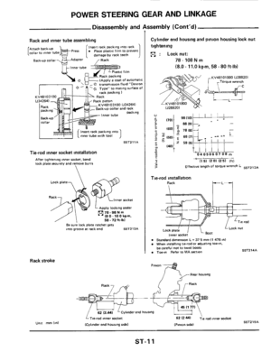
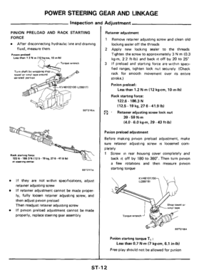
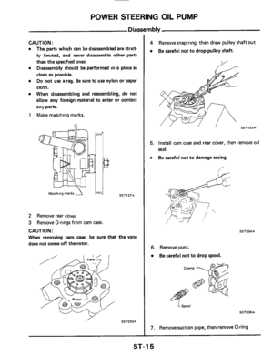
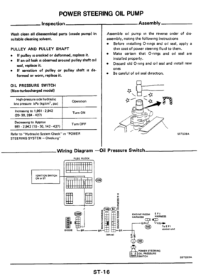
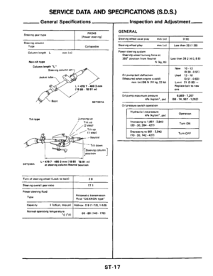
POWER STEERING GEAR AND LINKAGE
Disassembly and Assembly
0 Do not disassemble unless repairing to stop oil leak, replacing tie-rod and tie-rod inner rocket ball joint, or for various
adjustments.
0 Do not reuse O-rings or oil seals.
0 When assembling, apply a coat of oil to mating surfaces of O-rings and 011 seals
0 When assembling, be careful not to damage oil seals
0 Before starting work, thoroughly clean all parts in cleaning solvent or automatic transmission fluid "Dexron Type" and
blow dry with compressed air, if available.
0 After assembling tie-rod inner socket to rack & housing ASSY, check rack stroke (refer to "Rack stroke")
Lock nut
Refer to "Cylinder end housing and Refer to 'Tie-md inner Locket mtallation"
7 .... . . , . pmon housing lock nuts tight !e","." -
&?; '(80 100.58-72)
78.108
[Using tool KV48101800
when assembling ram ana cylinder end housing ASSY, becareful not to damage 011 seal
"18 0.11 0,58.80)
e]'
/ I
Refer to
'Tne-rod ,"stallatlo""
, collar
' @,e3
14.20)
be careful not to damage rack packing inner tube anernblong" (91 (2.0.2.7.
I.
Rad. and inner tubearrrnblmg
pjl N m (kgm. ft-lb)
Greaseup winti
e] Lubrication points
@ Donot reuse a
ST-8