Page 9 of 20
POWER STEERING GEAR AND LINKAGE
Disassembly and Assembly (Cont'd)
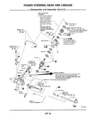
Rear hourmg cover installation Wlth retainer adlusting screw fully loosened.
tighten rear housing cover IO that pinion
starting force settles a1 the rpeclfied value, then lock 11 with lock
nut
For detads, refer to "PINION PRELOAD AND RACK STARTING m78-137(80-140.58-1011
FORCE" [Uringtool KV48101600 (J28818)
Rear housing cover lock nut
and KV48101700 (JZ881911 Rear housing cover
hourmg cover ASSY, be careful not IO damage 011 seal with pinion
Retainer inRallatinn Install retainer 20 that pinion preload and rack starting force settle at the specified value For details, refer to "PINION PRELOAD AND
RACK STARTING FORCE"
Refer to "Tie-rod inner socket mmllation"
(8 0.10 0,58 - 721
Refer 10 '7ie-md inrtallatmn''
L;, SST209A
ST-9
Page 10 of 20

0 Refer to \"Tie-rod inner socket installation\",
\"Tie-rod installation\", and \"Rack stroke\"
-
ASSEMBLY
Before starting work,")
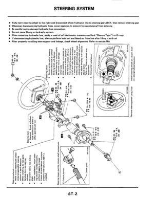
POWER STEERING GEAR AND LINKAGE
Disassembly and Assembly (Cont'd)
0 Refer to "Tie-rod inner socket installation",
"Tie-rod installation", and "Rack stroke"
-
ASSEMBLY
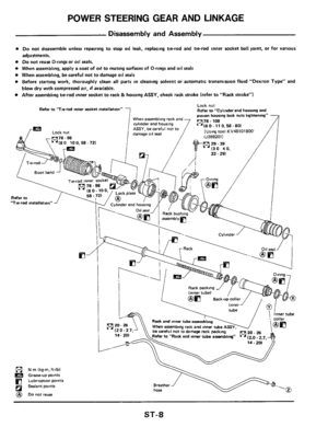
Before starting work, thoroughly clean all parts
in cleaning solvent or automatic transmission
fluid "Dexron Type" and blow dry with com-
pressed air,
if available
Do not reuse old oil seal, packing and O-ring
Always
install new ones
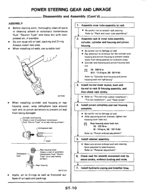
When installing oil
seals, use suitable tool
SST548
When installing cylinder end housing or rear
housing cover, wrap cellophane tape around
rack end
or pinion serrations to prevent oil seal
from being damaged
Cylmder end housing (Apply a coat of automatrc transmission fluid "Oexron Type" to 081 seal mating surface I
rCellophane tape
a- - Rack
Rear housng cover IA~ply a coat of automatic transmission fluid "Dexron Type" to 011 seal mating
SSTZlOA
Apply oil to O-rings as well as frictional sur.
faces of oil
seals and packings
Refer to "Rack and inner tube assembling" v
2. Assemble rack & inner tube assembly,
cylinder, cylinder end housing and pinion
housina.
I 0 Be careful not to damage oil seal
0 Pay attention to dlrection for the cylinder end
housing and pinion housing to prevent undue
stress from being applied to hydraulic pipes
0 Cylinder end housing and pinion housing lock
nut
p1 78-108Nm
(8 0 . 11.0 kg-m, 58 - 80 ft-lb)
Refer to "Cylinder end housing and pinion
housing lock nut tightening"
4. Install pinion complete and rear housing
complete.
I
0 Be careful not to damage oil seal
0 After adjusting pinion preload, tighten real
housing cover lock nut
p1 78 - 137 N.m
(8 - 14 kg-m, 58. 101 ft-lbl
Rear housing cover lock nut.
Refer to "Pinion preload adjustment"
5. Install retainer assembly.
force adjusted to specifications
Refer to "Retainer adjustment"
6. Check rack for smooth movement over its
entire stroke, without binding and noise. I
7. Install hydraulic piping and breather hose.
ST- 1 0
Page 11 of 20

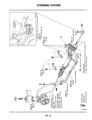
POWER STEERING GEAR AND LINKAGE
1701.
I601
I501
Disassembly and
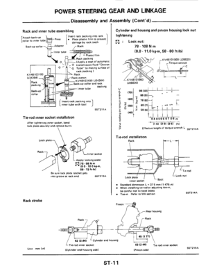
Rack and inner tube assembling
-
1
Insert rack packing into rack
damage by rack teeth Attach back-up
oat of automatic 80" fluid "Dexion * 1 - n '6 Type" to matlng surface of rack packing 1 ack
k pnrton
KV48103100 lJ342641
ackup collar and rack
1
Insert rack packing into mer tube with tool
SST211A
Tie-rod inner socket installation
After tightening inner socket, bend
lock plate securely and remove burrs
7 Lock plate
Inner socket
Apply locking sealer
78-98Nm ' I8 0 - 10 0 kern. 58.72 h-lbl / I Be sure lock plate ratchet gets into groove at rack end SST213A
Rack stroke
sembly (Cont'd)
Cylinder end housing and pinion housing lock nut
tightening
n : Locknut:
78 - 108 N m
(8.0 - 11.0 kg-m, 58 - 80 ft-lb)
Torque wrench
lJ288201 vc'
98 I101
88 I91
-
04050607 08 m
4' I1 51 I2 01 (2 51 Iff1
Effective length of torque wrench L ssT212A
Tie-rod installation
Lack nut Lock plate
Inner socket
Standard dimension L = 31 5 mm I1 476 In1 When installing tie-rod or adiustmg toe-,".
be careful not to twist boots Toe-," Refer to MA section
Pl"l.3"
Rear housing
I?-
- 62 lz.441 'Cylmder end housing /
SST'214A
iTie-rad inner socket
ICylmder
end hourlng sidel SSTZlBA IPinion sidel
ST-I 1
Page 12 of 20

POWER STEERING GEAR AND LINKAGE
Inspection and Adjustment
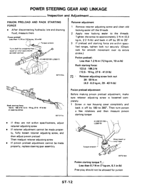
PINION PRELOAD AND RACK STARTING
FORCE
After disconnecting hydraulic line and draining
fluid, measure them
Pmon preload Less than 1 2 N m I12 kg-cm, 10 In-lbl
Turn shaft by wrappi towel or wnvl tape ar serrated portion
102100 (J288171
SST216A
Rack starting force 122 6.1863 N I12 5- 19 kg.276 -41 9 Ibl at Steernng Ce"t.3,
SST217A
If they are not within specifications, adjust
retainer adjusting screw
If retainer adjustment cannot be made proper-
ly, fully loosen retainer adjusting screw, and
then adjust pinion preload
Then readjust retainer adjusting screw
If pinion preload adjustment cannot be made
properly, replace steering gear assembly
Retainer adjustment
1
2
3
R
Remove retainer adjusting screw and clean old
locking
sealer off the threads
Apply new locking sealer to the threads
Tighten
the screw to approximately 3 N rn (0.3
kg-m, 2 2 h-lb) and back it off by 20 to 25"
If preload and starting force are within speci-
fied ranges, tighten lock nut securely (Check
rack for smooth movement over
its entire
stroke.)
Pinion preload:
Less than 1.2 Nm 112 kgcm, 10 in-lb)
Rack starting force:
122.6
- 186.3 N
(12.5-19kg,276 -41.9lb)
. Retainer adjusting screw lock nut
39 - 59 Nm
(4.0 - 6.0 kgm, 29 - 43 ft-lb)
Pinion preload adjustment
Before making pinion preload adjustment, make
sure retainer adjusting screw
is loosened com-
pletely
1 Screw in rear housing cover completely and
back it off by 180 to 360". Then turn pinion
a few rotations and then measure pinion
starting torque
KV48101700
I or
SST218A
Pinion starting torque T, :
Free play should not be allowed for pinion
Less than 0.7 Nm (7 kg-cm, 6.1 in-lb)
ST-1 2
Page 13 of 20

POWER STEERING GEAR AND LINKAGE
inspection and Ac
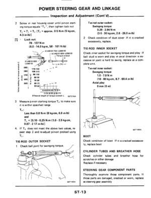
2 Screw in rear housing cover until pinion start-
ing torque equals "T,
", then tighten lock nut
T, =TI
+ T3 [T3 = approx. 0 5 N.m (5 kg-cm,
4.3 in-lb)]
pj . Locknut:
78.137 Nm
(8.0 - 14.0 kgrn, 58 - 101 ft-lb)
KV48101700 lJ288191 KV48101690 lJ28818)
1501 2 69 171 _. -.
? 1 59(61!* T %40.50 60.70 8 m - 9
5 4, I1 51 12 01 (2 51 lft)
Effective length of torque wrench L SST219A
Measure pinion starting torque T4 to make sure
it is within specified range
T4
:
3
Less than 0.8 N.m (8 kgcm, 6.9 in-lb)
and
TI
+ [0.10 - 0.25 Nm (1.0.2.5 kg-cm,
0.87.2 17 in-lb)]
4. If T, does not meet the above two values, re-
peat step
2 and re-adjust pinion preload using
T3.
TIE-ROD OUTER SOCKET
1 Check ball joint for swinging torque. /
SST130A
ustment (Cont'd)
Tie-rod outer socket:
Swinging toque
0.29.2.94 Nm
(3
0 - 30 kg-cm, 2.6 - 26.0 in-lb)
2 Check condition of dust cover If it is cracked
excessively, replace.
TIE-ROD INNER SOCKET
Check inner socket for swinging torque and play If
ball stud
is worn and play in axial direction IS ex-
cessive or joint
is hard to swing, replace as a com-
plete unit.
Tie-rod inner socket:
Swinging toque
1.0 - 7.8 N m
(10 - 80 kg-cm, 8.7 - 69.4 in-lb)
0 mm (0 in)
Axial play
n
it- * SSTl 06A
BOOT
Check condition of boot
If it is cracked excessive-
ly, replace boot
CYLINDER TUBES AND BREATHER HOSE
Check cylinder tubes and breather hose for
scratches or other damage
Replace if necessary
STEERING GEAR COMPONENT PARTS
Thoroughly examine those component parts.
If
those parts are damaged, cracked or worn, replace
as steering gear assembly
ST-1 3
Page 14 of 20
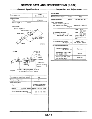
![NISSAN 300ZX 1984 Z31 Steering System Workshop Manual POWER STEERING OIL PUMP
Connector Ispool cover1 Flexible hose
69-78
38.52 mi70-8051 1 A Washe2 Connector bolt
7 . I 0 9- 12 (09.12.65 -871 13 9.5 3,28 - 381
s,,rr,nn ",no.... I
36-51] --I ..I](/manual-img/5/578/w960_578-13.png "NISSAN 300ZX 1984 Z31 Steering System Workshop Manual POWER STEERING OIL PUMP
Connector Ispool cover1 Flexible hose
69-78
38.52 mi70-8051 1 A Washe2 Connector bolt
7 . I 0 9- 12 (09.12.65 -871 13 9.5 3,28 - 381
s,,rr,nn \",no.... I
36-51] --I ..I")
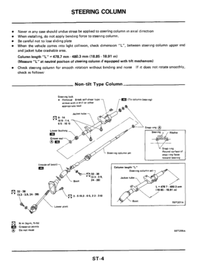
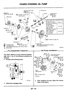
POWER STEERING OIL PUMP
Connector Ispool cover1 Flexible hose
69-78
38.52 mi7'0-80'51 1 A Washe2 Connector bolt
7 . I 0 9- 12 (09.12.65 -871 13 9.5 3,28 - 381
s,,rr,nn ",no.... I
36-51] --I ..I.. r,r_
re switch (Non-turbocharged model)
Htgh-pressure ride
hydraultc
line pressure
1,961
- 2,942 kPa
(20.30 kg/cm' ,
Decreasing to aPProx
Turn ON
981 -2,942 kPa
(10 - 30 kg/cm' ,
142-427~511 1
42 I3 2 -43.23- 31)
L Pulley shaft (When assembling pulley shaft. be careful
not to damage oil seal lip1 seal
am
(41 31 -42 13.2 - 4.3, 23 - 311 (41 N m (kg-m. ft-lb)
fl Lubricatzon points (with automatic transmission fluid "Dexron Type") @ ~onotreu~
- Pre-disassembly Inspection
The power steering oil pump should be disassem-
bled only
d any of the following conditions are
ObSWVed.
Oil leak at the following points
SST126A
Deformed or damaged pulley
SST220A
Oil Pump Installation
mounting bracket
steering pump
(41 N m (kgm, ft-lbl
SST221A
m16-21 (1.6-21,
12.15)
After installing oil pump, adjust belt tension.
Refer to MA section.
ST-1 4
Page 15 of 20
POWER STEERING OIL PUMP
Diassernbl y
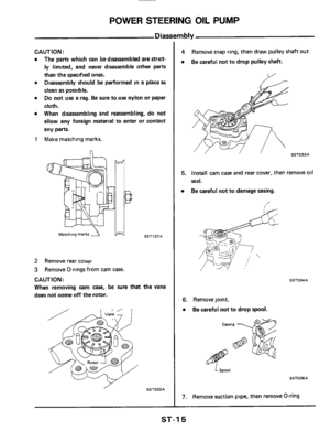
CAUTION:
a The parts which can be disassembled are strict-
ly limited, and never disassemble other parts
than the specified ones.
Disassembly should be performed in
a place as
clean as possible.
Do not use a rag. Be sure to use nylon or paper
cloth.
When disassembling and reassembling, do not
allow any foreign material to enter
or contact
any parts.
a
a
a
1 Make matching marks.
Matchmg marks 4 SSTl27A
2 Remove rear cover
3
CAUTION :
When removing cam case, be sure that the vane
does not come
off the rotor.
Remove O-rings from cam case.
SSTO32A ,
4
a
Remove snap ring, then draw pulley shaft out
Be careful not
to drop pulley shaft.
SST033A
5. Install cam case and rear cover, then remove 011
seal.
Be careful not to damage casing.
0
f
SST034A
6. Remove joint.
0 Be careful not to drop spool.
L spool
SSTOJSA
7. Remove suction pipe, then remove O-ring
ST-1 5
Page 16 of 20
 in
suitable cleaning solvent.
PULLEY AND PULLEY SHAFT
0
0
If pulley is cracked or deformed, replace it.")
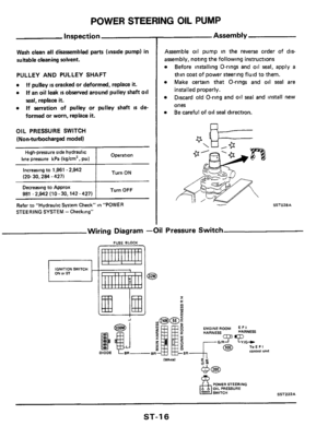
POWER STEERlNG OIL PUMP
Inspection
Wash clean all disassembled parts (inside pump) in
suitable cleaning solvent.
PULLEY AND PULLEY SHAFT
0
0
If pulley is cracked or deformed, replace it.
If an oil leak IS observed around pulley shaft oil
seal, replace it.
If serration of pulley or pulley shaft IS de-
formed
or worn, replace it.
0
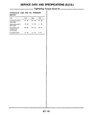
OIL PRESSURE SWITCH
(Non-turbocharged model)
Operation High-pressure side hydraulic
line pressure kPa (kglcm', psi) ~~
I Turn ON Increasing to 1,961 - 2,942
(20- 30,284 ~ 4271
Turn OFF Decreasing to Approx
981 .2,942 (10 - 30,142 - 427)
Refer to "Hydraulic
System Check" in "POWER
STEERING SYSTEM
- Checking"
Assembly
Assemble 011 pump in the reverse order of dts-
assembly, noting the following instructions
Before installing O-rings and oil seal, apply a
thin coat of power steering fluid to them.
Make certain that O-rings and oil
seal are
installed properly.
Discard old O-ring and oil
seal and install new
ones Be careful of
oil seal direction.
Wiring Diagram -Oil Pressure Switch
FUSE BLOCK
IGNITION SWITCH
I a
Y
Ln v)
E
ENGINE ROOM E I R HARNESS HARNESS
IWhnsl d'
POWER STEERING OIL PRESSURE
SST222A
ST-1 6

Rear hourmg cover installation Wlth retainer adlusting screw fully loosened.
tighten rear housing cover IO that pinion
startin")
