Page 9 of 22

DRIVE SHAFT-'"Tripod-Tripod" Type
Inspection
DRIVE SHAFT
Check for cracks or other damage Replace if
necessary
TRIPOD JOINT
Check spider assembly for bearing and washer
damage Replace spider assembly if necessary
Check slide joint housing and housing sub-
assembly for any damage Replace if necessary
Assembly
After drive shaft has been assembled, ensure
that
it moves smoothly over its entire range
without binding
Use NISSAN GENUINE GREASE or equiva-
lent after every overhaul
WHEEL SIDE
Be careful not to scratch boot with drive shaft
serration.
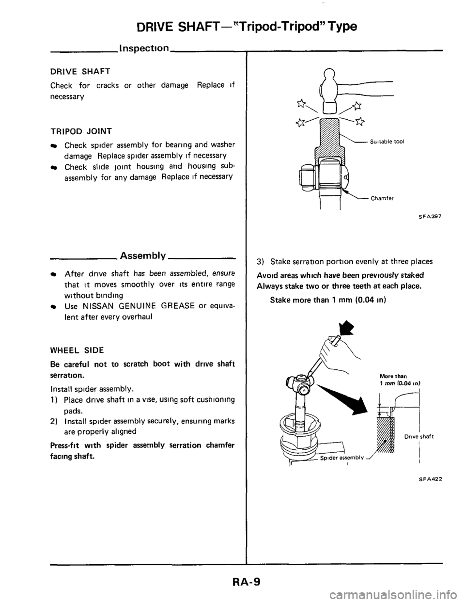
Install spider assembly.
1) Place drive shaft in a vise, using soft cushioning
pads.
2) Install spider assembly securely, ensuring marks
are properly aligned
Press-fit with spider assembly serration chamfer
facing shaft.
* k
Sultable tool
Chamfer
3) Stake serration portion evenly at three places
Avoid
areas which have been previously staked
Always stake
two or three teeth at each place.
Stake more than 1 mm (0.04 in)
More than 1 mm 10.04 m)
SFAd22
Page 10 of 22

DRIVE SHAFT-'"Tripod-Tripod" Type
Assemb
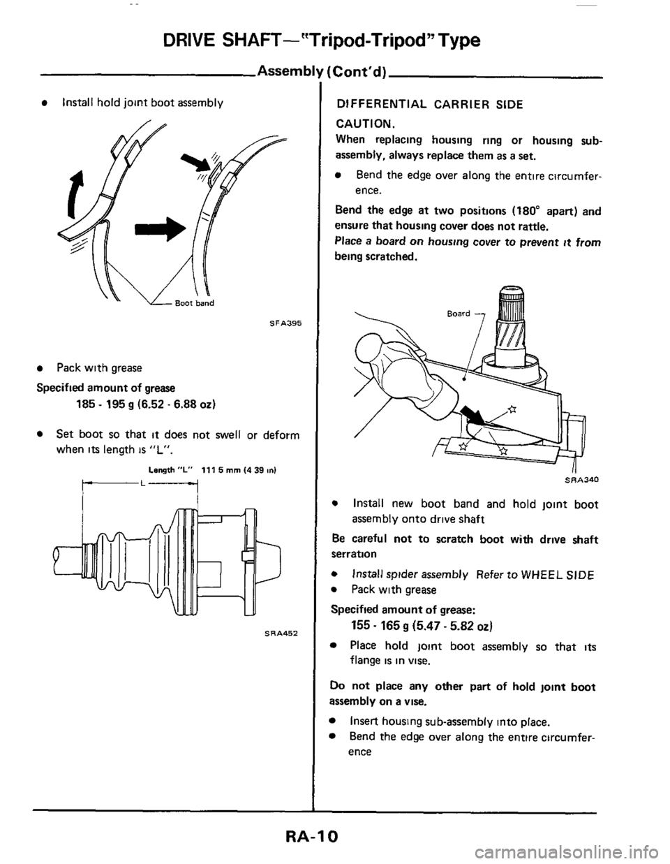
Install hold joint boot assembly
SFA395
Pack with grease
Specified amount of grease
185 - 195 g (6.52 - 6.88 02)
Set boot so that it does not swell or deform
when
its length is "L".
Length "L" 111 5 mm (4 39 on1
SRA452
[Cont'd)
DIFFERENTIAL CARRIER SIDE
CAUTION.
When replacing housing ring or housing sub-
assembly, always replace them as a set.
Bend the edge over along the entire circumfer-
ence.
Bend
the edge at two positions (180" apart) and
ensure that housing cover
does not rattle.
Place a board
on housing cover to prevent it from
being scratched.
~~~340
0 Install new boot band and hold joint boot
Be careful
not to scratch boot with drive shaft
serration
0 Install spider assembly Refer to WHEEL SIDE
0 Pack with grease
Specified amount of grease:
Place hold joint boot assembly so that its
assembly onto drive shaft
155 - 165 g (5.47 - 5.82 OZ)
flange is in vise.
Do not place any other part of hold joint boot
assembly on a vise.
Insert housing sub-assembly into place.
Bend
the edge over along the entire circumfer-
ence
RA-10
Page 11 of 22
DRIVE SHAFT--"Tripod-Tripod" Type
Assem bl1
Bend the edge at two positions (180" apart) and
ensure that housing sub-assembly does not rattle.
Place
a board on housing sub-assembly to prevent
it from being scratched.
SRA341
e Apply sealant
Cont'd)
e Set boot so that it does not swell or deform
when
its length is "L"
Length "L" 92 5 mm 13 642 m)
IL1
SRA453
RA-11
Page 12 of 22
DRIVE SHAFT- “Double Offset-Birfield” Type
S R A449
CAUTION.
Joints on
both sides are non-disassembling type.
Inspection
DRIVE SHAFT
Check for cracks
or other damage Replace dnve
shaft assembly if necessary
BlRFlELD JOINT
Replace drive shaft assembly if birfield joint
is
damaged
DOUBLE OFFSET JOINT
Replace drive shaft assembly if double offset
joint
is damaged
BOOT
Replace drive shaft assembly
if boot IS fatigued,
cracked or worn
RA-12
Page 13 of 22
REAR SUSPENSION
(2 0.28,14-201
(~hayr replace when
lnSuletOr coyer
Shack absorber
mounting
mulator
69 - 88 (7 .9,51 - 651
Bound bumper -
upper rpmg seat rubber
Dust cover -
Shock absorber
~~~er rpmg seat rubber
L9) 59.78 (6.8.43.58)
Differential mounting Insulator
Member msulator stopper
suspension member
arsemblv
(1 6-2 1.12-151
- 39 13.4.22 -291 Member tnsulator
Rubber bushing
spring seat stay 98-118110-12,
16-21116-21.12-151
n 59 - 78 16.8,43-581
23-311 Bushing
n 31-42 (3 2-43.
23.311
N rn (kg-m, ft-lbl
S R A454
RA-13
Page 14 of 22
REAR SUSPENSION
Stabilizer Bar
REMOVAL AND INSTALLATION
Remove stabilizer bar
SRA458
Final tightening should be carried out at curb
weight with
tires on ground
INSPECTION
Check stabilizer bar for deformation or cracks
Replace if necessary
Check rubber bushings for deterioration or
cracks Replace if necessary.
Shock Absorber
(Non - adjustable type)
REMOVAL AND INSTALLATION
Remove shock absorber upper end nut.
Disconnect shock absorber lower end.
SRA459
Final tightening should be carried out at curb
weight with tires on ground
INSPECTION
Check all rubber parts for wear, cracks, damage
or deformation Replace if necessary.
If oil leakage occurs, replace shock absorber
assembly.
Inspect threads for cracks or other damage
Replace if necessary
Inspect piston rod for cracks, deformation or
other damage Replace shock absorber
assembly if necessary
ASSEMBLY
Tape around piston rod
so as not to damage it
when tightening lock nut.
/-Washer
insulator cover
RA-14
Page 15 of 22
REAR SUSPENSION
Coil Spring
REMOVAL AND INSTALLATION
Jack up vehicle after setting spring compressor.
Then remove coil spring
When installing, correctly place coil spring in
the lower sprlng
seat rubber (Flat face of
sDrina
IS on top ) .-
Upper spring seat rubber
(Flat face)
Cob1 spring
!
~ower spring seat rubber SRA462
Suspen
REMOVAL AND INSTALLATION
I NSP ECTl ON
Check coil spring for yield, deformatlon or
cracks Replace
if necessary.
0 Check upper and lower spring seat rubbers for
wear, cracks or damage Replace if necessary
3n Arm
I/ I
SRA463
RA-15
Page 16 of 22

REAR SUSPENSION
Suspension Arm (Cont'd)
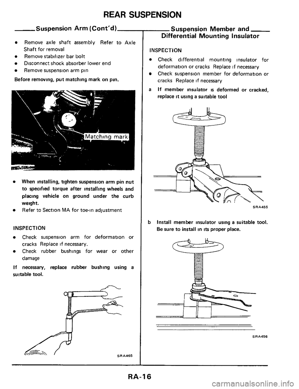
Remove axle shaft assembly Refer to Axle
Remove stabilizer bar bolt
Remove suspension arm pin
Before removing, put matching mark on pin.
Shaft for removal
Disconnect shock absorber lower end
When installing, tighten suspension arm pin nut
to specified torque after installing wheels and
placing vehicle on ground under the curb
weight. Refer to Section MA for toe-in adjustment
INSPECTION
Check suspension arm for deformation or
Check rubber bushings for wear or other
If necessary, replace rubber bushing using a
suitable tool.
cracks Replace if necessary.
damage
SRA465
Suspension Member and
Differential Mounting Insulator
INSPECTION
Check differential mounting insulator for
deformation or cracks Replace if necessary
Check suspension member for deformation or
cracks Replace if necessary
If member insulator is deformed or cracked,
replace
it using a suitable tool
a
SRA455
b Install member insulator using a suitable tool.
Be sure to install in
its proper place.
SRA456
RA-16