Page 2 of 22
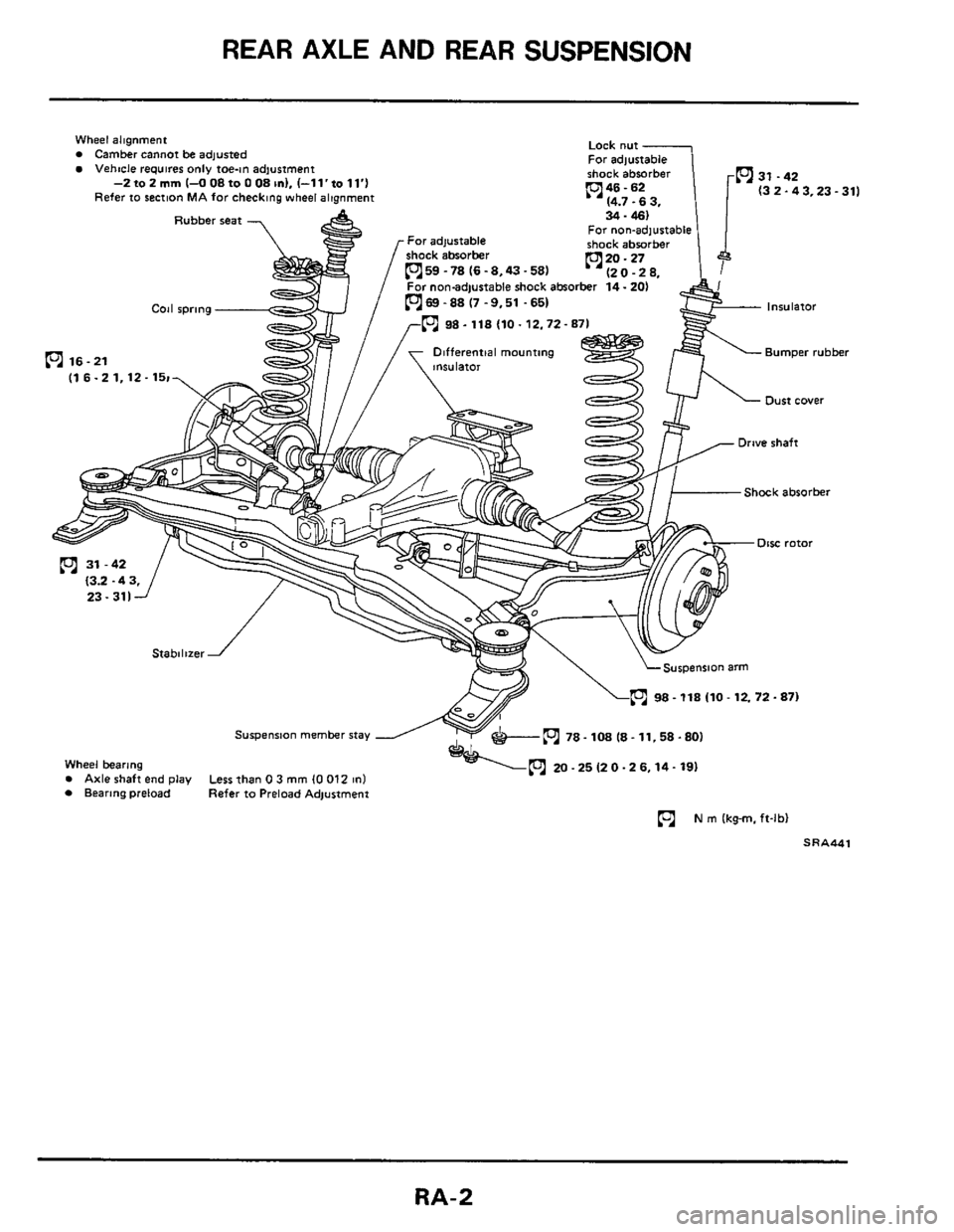
REAR AXLE AND REAR SUSPENSION
Wheel alignment Camber Cannot be adjusted Vehtcle requires only toe-in adjustment
(3 2-43.23-311
Rubber seat For non-adjustable
059 -78 (6 -8.43.58)
For non-adjustable shock absorber 14.201
0 98 - 118 (10.12.72- 8
Differential mounting Bumper rubber 0 16-21
(1 6.2 1,12.15r
Shock absorber
0 98 - 118 (10 - 12.72.87)
Suspenrian member stay
Wheel bearing Axle shaft end play Less than 0 3 mm (0 012 1n1 Bearing preload Refer to Preload Adjustment
N m lkg-m. ft-lbl
SRA441
RA-2
Page 6 of 22
DRIVE SHAFT
Removal and Installation
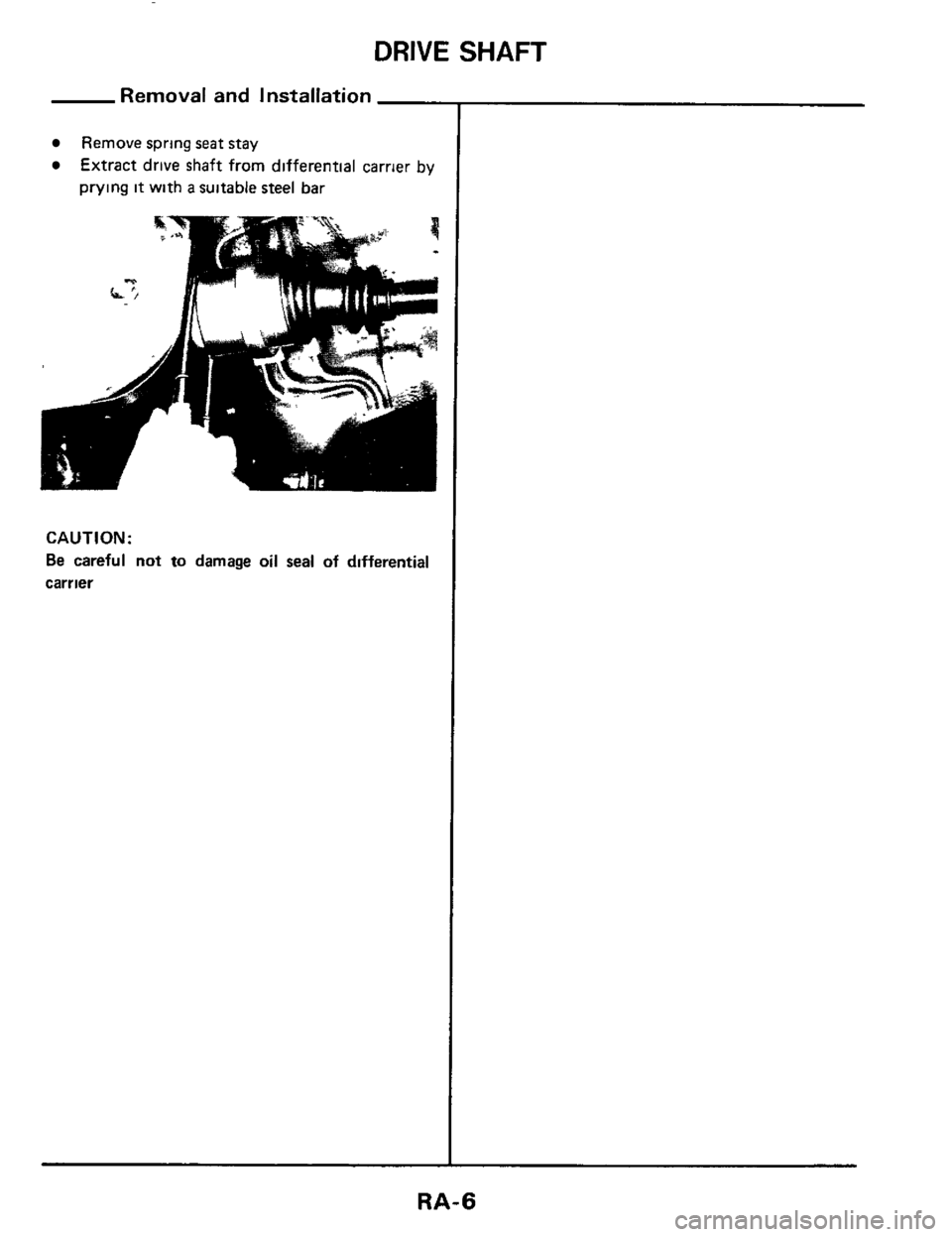
Remove spring seat stay
Extract drive shaft from differential carrier by
prying
it with a suitable steel bar
CAUTl ON :
Be careful not to damage oil seal of differential
carrier
RA-6
Page 7 of 22
DRIVE SHAFT-'"Tripod-Tripod" Type
Cmular clip Make sure c~rcl#p 1s properly meshed wth ride gear and will not come out Sllde loin1 boot'
slide pnt housing
Spider assembly
Wheel ride
ITripod IOd
Housing Cover' Differential carrier side (Tripod ioint)
Houslng sub-assembly
'Always replace once they have been disassembled
s R A448
Hold pmt boot assembly.
Boot band'
Disas
WHEEL SIDE
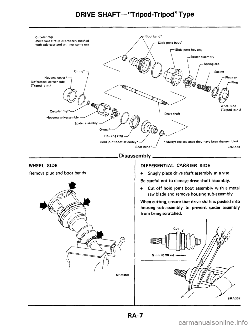
Remove plug and boot bands
mbly
DIFFERENTIAL CARRIER SIDE
Snugly place drive shaft assembly in a vise
Be careful not to damage drive shaft assembly.
Cut off hold jomt boot assembly wlth a metal
saw blade and remove housing sub-assembly
When cutting, ensure that drive shaft
is pushed into
housing sub-assembly to prevent spider assembly
from being scratched.
RA-7
Page 10 of 22
DRIVE SHAFT-'"Tripod-Tripod" Type
Assemb
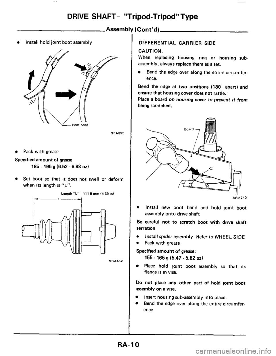
Install hold joint boot assembly
SFA395
Pack with grease
Specified amount of grease
185 - 195 g (6.52 - 6.88 02)
Set boot so that it does not swell or deform
when
its length is "L".
Length "L" 111 5 mm (4 39 on1
SRA452
[Cont'd)
DIFFERENTIAL CARRIER SIDE
CAUTION.
When replacing housing ring or housing sub-
assembly, always replace them as a set.
Bend the edge over along the entire circumfer-
ence.
Bend
the edge at two positions (180" apart) and
ensure that housing cover
does not rattle.
Place a board
on housing cover to prevent it from
being scratched.
~~~340
0 Install new boot band and hold joint boot
Be careful
not to scratch boot with drive shaft
serration
0 Install spider assembly Refer to WHEEL SIDE
0 Pack with grease
Specified amount of grease:
Place hold joint boot assembly so that its
assembly onto drive shaft
155 - 165 g (5.47 - 5.82 OZ)
flange is in vise.
Do not place any other part of hold joint boot
assembly on a vise.
Insert housing sub-assembly into place.
Bend
the edge over along the entire circumfer-
ence
RA-10
Page 13 of 22
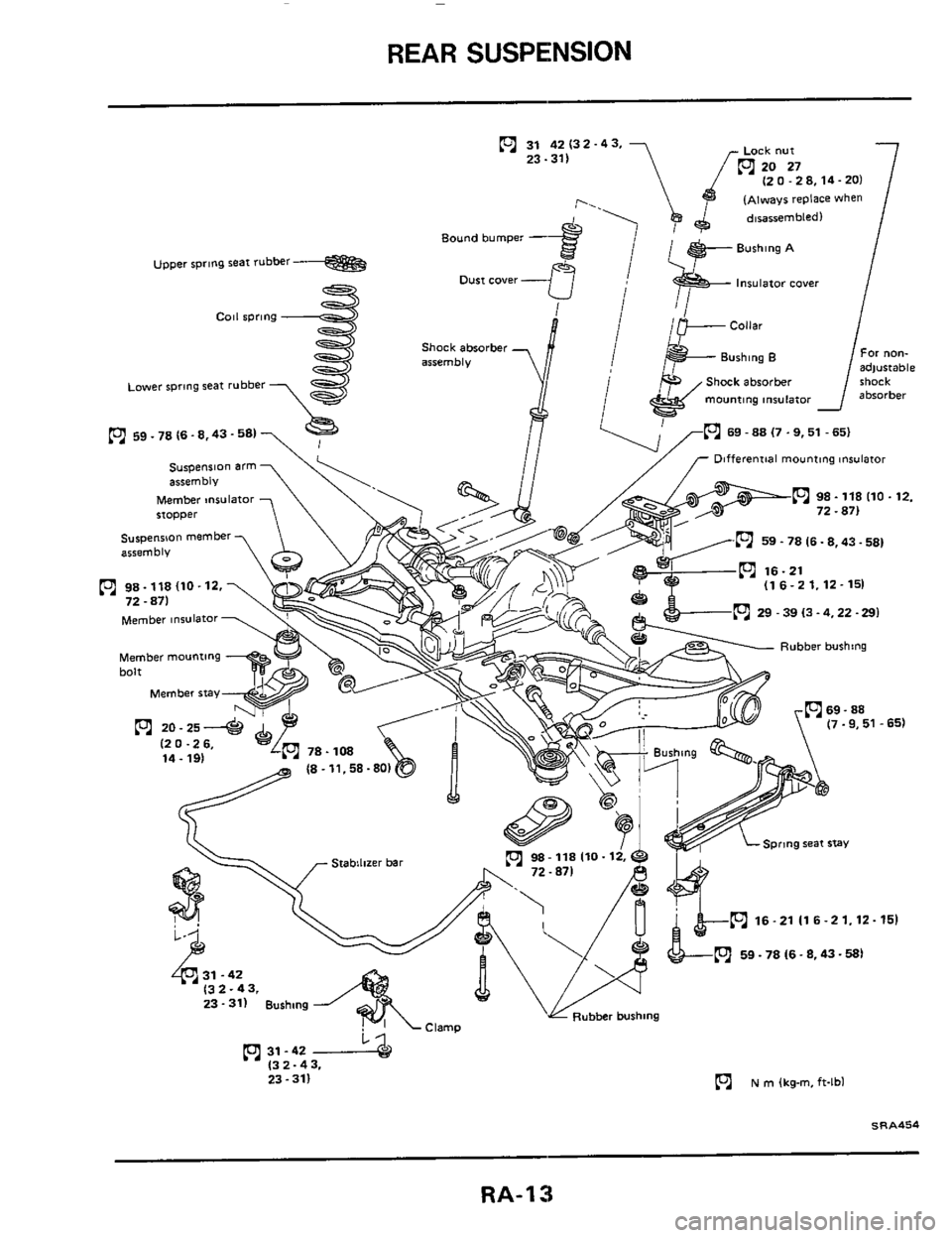
REAR SUSPENSION
(2 0.28,14-201
(~hayr replace when
lnSuletOr coyer
Shack absorber
mounting
mulator
69 - 88 (7 .9,51 - 651
Bound bumper -
upper rpmg seat rubber
Dust cover -
Shock absorber
~~~er rpmg seat rubber
L9) 59.78 (6.8.43.58)
Differential mounting Insulator
Member msulator stopper
suspension member
arsemblv
(1 6-2 1.12-151
- 39 13.4.22 -291 Member tnsulator
Rubber bushing
spring seat stay 98-118110-12,
16-21116-21.12-151
n 59 - 78 16.8,43-581
23-311 Bushing
n 31-42 (3 2-43.
23.311
N rn (kg-m, ft-lbl
S R A454
RA-13
Page 16 of 22
REAR SUSPENSION
Suspension Arm (Cont'd)
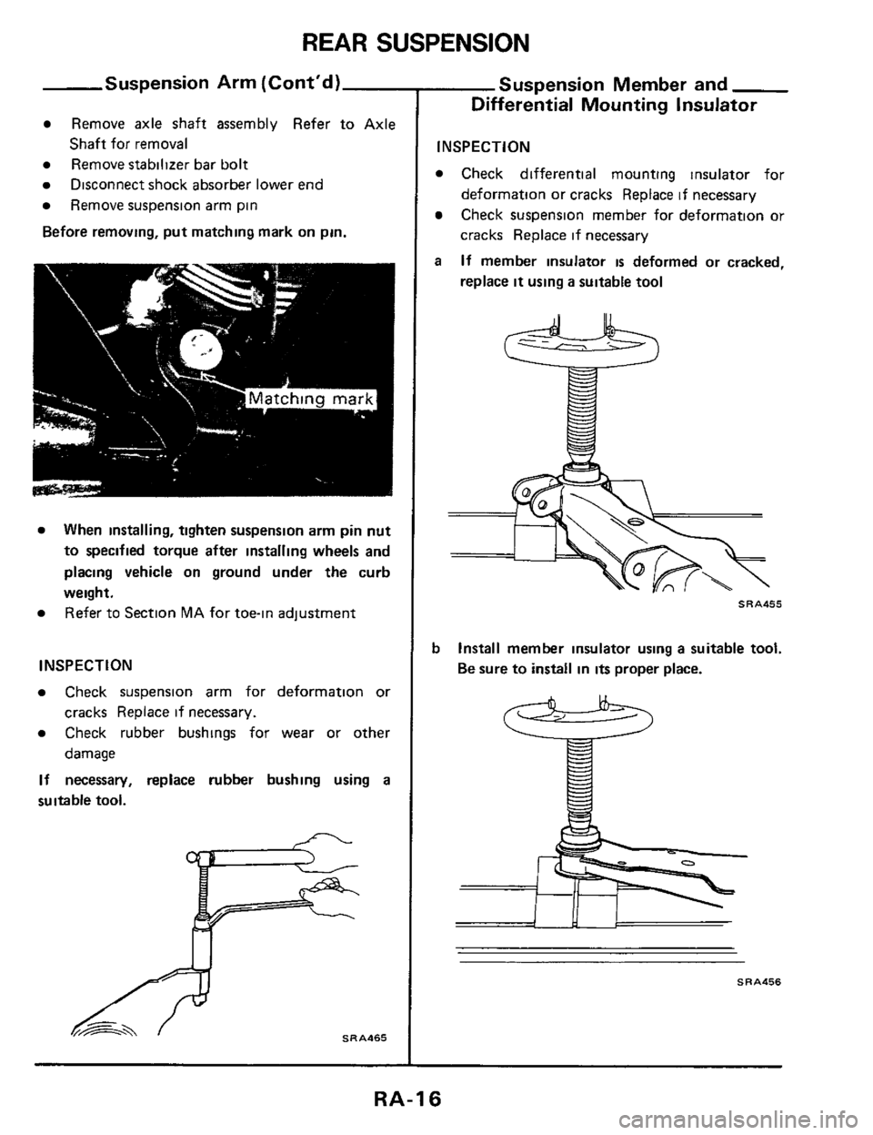
Remove axle shaft assembly Refer to Axle
Remove stabilizer bar bolt
Remove suspension arm pin
Before removing, put matching mark on pin.
Shaft for removal
Disconnect shock absorber lower end
When installing, tighten suspension arm pin nut
to specified torque after installing wheels and
placing vehicle on ground under the curb
weight. Refer to Section MA for toe-in adjustment
INSPECTION
Check suspension arm for deformation or
Check rubber bushings for wear or other
If necessary, replace rubber bushing using a
suitable tool.
cracks Replace if necessary.
damage
SRA465
Suspension Member and
Differential Mounting Insulator
INSPECTION
Check differential mounting insulator for
deformation or cracks Replace if necessary
Check suspension member for deformation or
cracks Replace if necessary
If member insulator is deformed or cracked,
replace
it using a suitable tool
a
SRA455
b Install member insulator using a suitable tool.
Be sure to install in
its proper place.
SRA456
RA-16
Page 17 of 22
REAR SUSPENSION
Suspension Member and
Differential Mounting Insulator
(Cont’d)
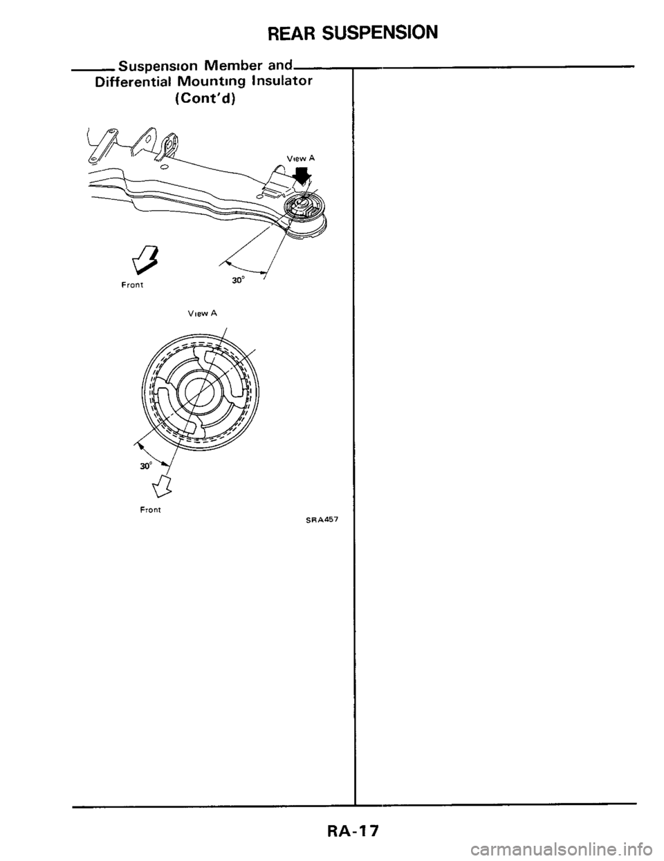
View A
Front SRA457
RA-17
Page 21 of 22
SERVICE DATA AND SPECIFICATIONS (S.D.S.)
-General Specifications (Cont'd)-
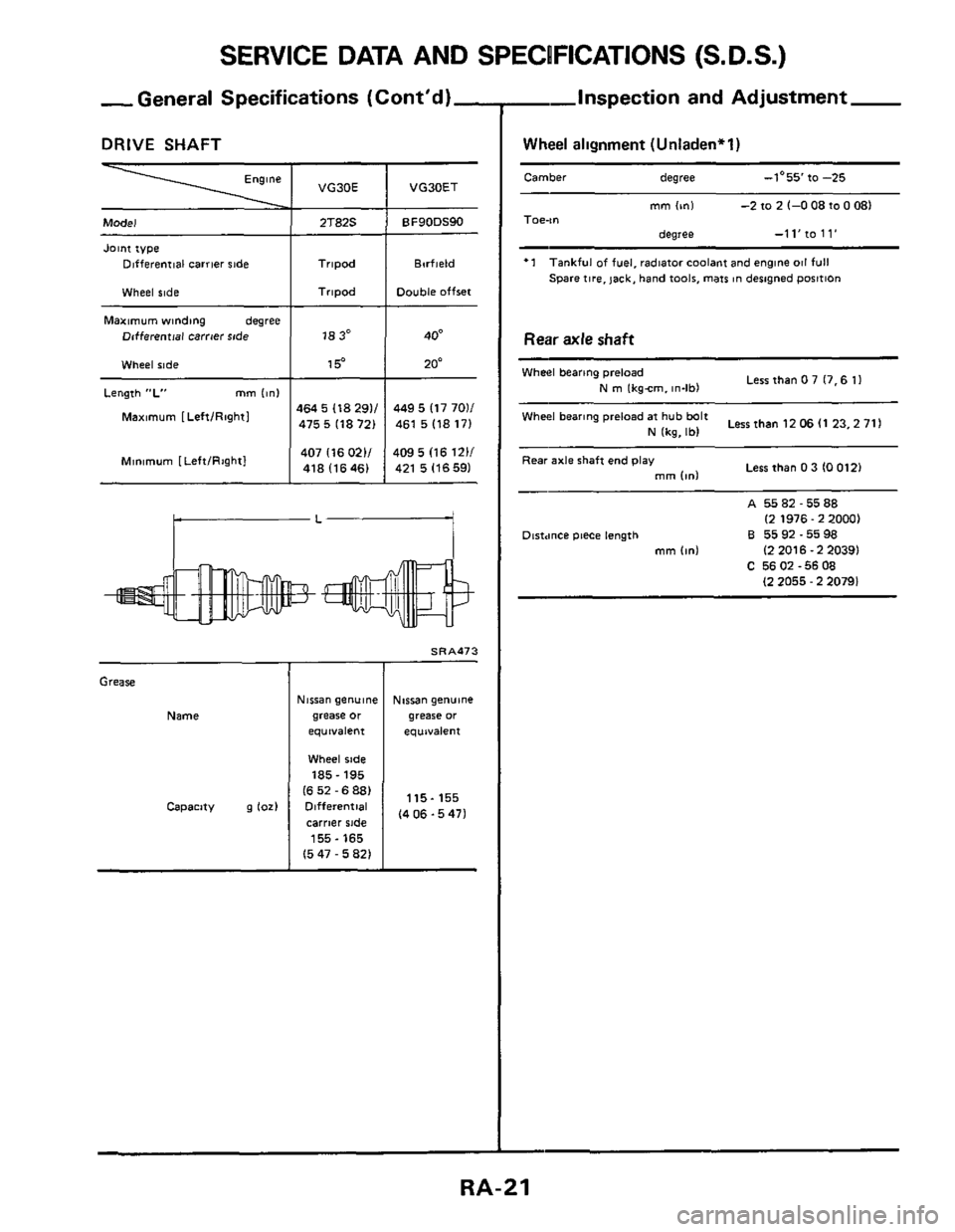
DRIVE SHAFT
Engine
F
Model
Joint type Dlfferenrlal carrier ride
Wheel side
Maximum winding degree
Dcfferential carrier $#de
Wheel ride
Length "L" mm linl
Maximum [LeftIRightl
Minimum [Left/Rightl
VG30E
2T82S
Tripod
Tripod
18 3"
1 5"
464 5 118 291/
475
5 118 721
407 I16
0211 418 I16461
VG30ET
BF90DS90
Barfield
Double offset
40'
20-
449 5 117 7011
461
5 118 171
409
5 (16 1211
421 5 116 591
rL-
Grease
Name
Capacity 9 lo21
Nisran genuine
grease
or
equivalent
Wheel side
185- 195
I6 52 - 6 881
Differential
carrier side
155-165
15 47 - 5 821
d
SRA473
Nirsan genubne
grease or
equivalent
115-155
I4
06 -5 471
Inspection and Adjustment -
Wheel alignment (Unladen*l)
Camber degree -1'55 to -25 -
mm On1 -2 to 2 1-0 08 to 0 081 Toe-," degree -11'10 11'
'1 Tankful of fuel. radiator coolant and englne 011 full
Spare
tire, jack, hand took, mars ~n designed p~sitlon
Rear axle shaft
LerrthanO7 17.611 Wheel bearing preload
N m lkgcm. in-lbl
Lessthan120611 23,2711 Wheel bearing preload at hub bdt
N lkg, Ibl
Less than 0 3 IO 0121 Rear axle shaft end play
mm Id - A 5582-5588
Dtrtmce piece length
B 5592-5598
C 5602-5608
(2 1976.2 20001
mm
Id I2 2016.2 20391
I2 2055 - 2 20791
RA-21