1984 NISSAN 300ZX suspension
[x] Cancel search: suspensionPage 4 of 15

DIFFERENTIAL CARRIER (fvoe R200)
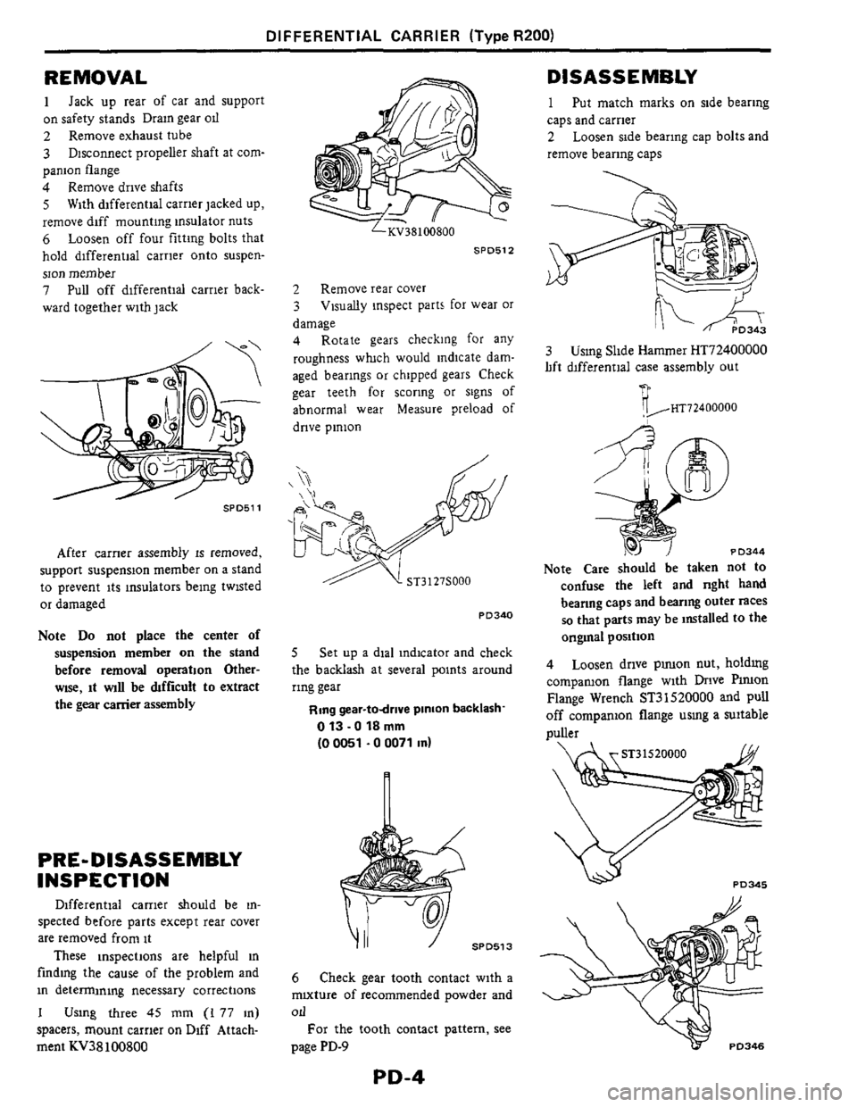
REMOVAL
1
on safety stands Drain gear od
2 Remove exhaust tube
3
panion flange
4 Remove drive shafts
5 With differential carrier jacked up,
remove diff mounting insulator nuts
6 Loosen off four fitting bolts that
hold differential carrier onto suspen-
son member
7 Pull off differential carrier back-
ward together with jack
Jack up rear of car and support
Disconnect propeller shaft at com-
SPD511
After carner assembly IS removed,
support suspension member
on a stand
to prevent its insulators being twisted
or damaged
Note Do not place the center of
suspension member on the stand
before removal operation Other-
wse, it wll be &fficult to extract
the
gear carrier assembly
PRE- DISASSEMBLY
INSPECTION
Differential carrier should be in-
spected before parts except rear cover
are removed from it
These inspections are helpful in
finding the cause of the problem and
in determining necessary corrections
1 Using three 45 mm (I 77 in)
spacers, mount carrier
on Diff Attach-
ment KV38100800
LKV38100800
SPD512
2 Remove rear cover
3 Visually inspect parts for wear or
damage
4 Rotate gears checking for any
roughness whch would indicate dam-
aged bearings or chipped gears Check
gear teeth for scorlng or signs
of
abnormal wear Measure preload of
drive pinion
PD340
5 Set up a dial indicator and check
the backlash at several points around
ring gear
Ring gear-todrive pinion backlash-
0 13 -0 18 mm
(0 0051 . 0 0071 in)
SPD513
6 Check gear tooth contact with a
mxture of recommended powder and
Oll
For the tooth contact pattern, see
page PD-9
PD-4
DlSASS E MBLY
1
caps and carrier
2
remove bearing caps
Put match marks on side bearing
Loosen side bearing cap bolts and
3 Usmg Slide Hammer HT72400000
lift hfferential case assembly out
PD344
Note Care should be taken not to
confuse the left and nght hand
beanng caps and bearing outer races
SO that parts may be installed to the
ongmal position
4 Loosen dnve puuon nut, holdmg
compamon flange with Dnve
Plruon
Flange Wrench ST31520000 and pull
off companion flange usmg a suitable
Duller
Page 10 of 15

DIFFERENTIAL CARRIER (Type R200)
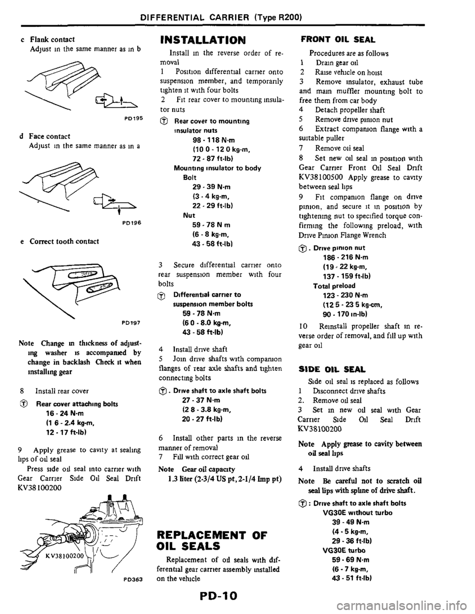
c Flankcontact
Adjust in the same manner as in b
PO195
d Face contact
Adjust in the same manner as in a
PD196
e Correct tooth contact
. PD197
Note Change m thickness of adjust-
ing washer
is accompamd by
change in backlash Check it when
installing
gear
8 Install rear cover
@ Rear cover attaching bolts
16 - 24 Nm
(1 6 - 2.4 kg-m,
12.17 ft-lb)
9 Apply grease to cavity at sealing
lips of od seal
Press side od seal into carrier with
Gear Carrier Side
Od Seal Drift
KV38 100200
PO363
INSTALLATION
Install in the reverse order of re.
moval
1 Position differential carrier onto
suspension member, and temporarily
tighten
it with four bolts
2 Fit rear cover to mounting insula-
tor nuts
@ Rear cover to mounting
insulator nuts
98.118 Nm
(10 0 - 12 0 kg-m,
72.87 ft-lbl
Mounting insulator to body
Bolt
29.39 Nm
(3.4 kg-m,
22.29 ft-lbl
59 -78 N m
(6.8 kg-m,
43.58 ft-lb)
Nut
3 Secure differential carrier onto
rear suspension member with four
bolts
@ Differentlal carrier to
59 - 78 Nm
(6 0 .8.0 kg-m,
43 - 58 ft-lbl
suspension member bolts
4 Install drive shaft
8 Join drive shafts with comparuon
flanges
of rear axle shafts and tighten
connectmg bolts
0. Drive shaft to axle shaft bolts
27 - 37 Nm
(2 8 - 3.8 kg-m,
20 .27 ft-l b)
6
manner of removal
7
Note Gear oil capaclty
Install other parts in the reverse
FIU with correct gear od
1.3liter(2-3/4USpt,2-1/4Imp pt)
REPLACEMENT OF
OIL SEALS
Replacement of od seals with dif-
ferential gear carrier assembly mstalled
on the velucle
FRONT OIL SEAL
Procedures are as follows
1 Dram gear oil
2 Raise vehicle on hoist
3 Remove insulator, exhaust tube
and main muffler mounting bolt to
free them from car body
4 Detach propeller shaft
8 Remove drive piruon nut
6
suitable puller
7 Remove oil seal
8 Set new oil seal in position with
Gear Carner Front Oil Seal Dnft
KV38100800 Apply grease to canty
between seal lips
9 Fit companion flange on dnve
pinion, and secure it in position by
tightening nut to specified torque con-
firming the following preload, with
Drive Pinion Flange Wrench
0. Drive pinion nut
186 - 216 N.m
(1 9122 kg-m,
137
- 159ft-lb)
123 - 230 Nm
(12 5 - 23 5 kgcm,
90. 170 in-lbl
Extract comparuon flange with a
Total preload
10 Reinstall propeller shaft in re-
verse order of removal, and fill up with
gear oil
SIDE OIL SEAL
1 hsconnect drive shafts
2. Remove od seal
3 Set in new OII seal with Gear
Carrier Side
011 Seal Drift
KV38100200
Note Apply grease to cavity between
oil seal IIps
Side od seal is replaced as follows
4 Install drive shafts
Note
Be careful not to scratch oil
seal lips with sphne of drive shaft.
0 : Drive shaft to axle shaft bolts
39 - 49 N.m
(4.5 kg-m,
29 - 36 ft-lb)
VG3OE turbo
59.69 Nm
(6 - 7 kg-m,
43 - 51 ft-lb)
VG30E without turbo
Page 12 of 15

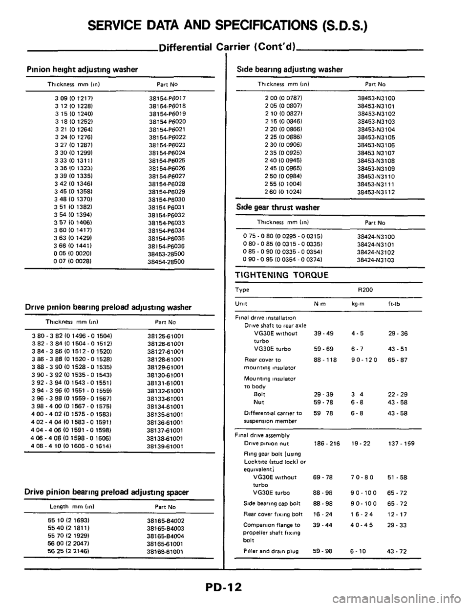
SERVICE DATA AND SPECIFICATIONS (S.D.S.)
Differential c
Pinion height adjusting washer
Thickness mm linl Part No
3 09 IO 12171 38154.P6017
3 12
10 1228) 38154P6018
3 15
(0 1240) 38154.P6019
3 18
IO 12521 38154P6020
3 21
IO 12641 38154.P6021
3 24 10 1276) 381 54-P6022
3 27
(0 12871 38154.P6023
3 30
IO 12991 38154-P6024
3331013111 38154-P6025
3 36
IO 1323) 38154-Pti026
3 39 IO 13351 38154.P6027
3 42 10 13461
381 54-P6028
3 45
IO 1358) 38154.P6029
3
48 (0 13701 38154-P6030
3 51 10 13821
381 54 P6031
3
54 IO 13941 38154-P6032
3 57
IO 14061 38154P6033
3
60 (0 1417) 38154.P6034
3 63
IO 14291 38154.P6035
3 66 (0 1441) 381 54-P6036
0 05 10 00201 38453-28500 0 07 (0 00281 38454-28600
Drive pinion bearing preload adjusting washer
Thlcknerr mm (In1 Part No
3 80 -3 82 10 1496 -0 15041 3812561001
3 82.3 84 10 1504- 0 15121 38126-61001
3 84.3
86 IO 1512 -0 15201 38127-61001
3 86.3 88 (0 1520-0 1528) 381 286 100 1
3 88 - 3 90 10 1528-0 15351 381 2961001
390-392101535-01543) 38130-61001
3 92.3 94
(0 1543 -0 15511 38131-61001
3
94 - 3 96 10 1551 .O 15591 3813261001
3 96.3 98
IO 1559-0 15671 3813361001
3 98
- 4 00 IO 1567 - 0 15751 381 34-61001
4
00 - 4 02 IO 1575-0 1583) 3813561001
4
02 - 4 04 10 1583 - 0 15911 3813661001
404-4
06 IO 1591 -0 1598) 3813761001
4
06 - 408 IO 1598-0 16061 38138-61001
408-410101606-01614) 38139-61001
Drive pinion bearing preload adjusting spacer
Length mm Id Part No
55 10 (2 16931 55 40 I2 181 11
55 70 I2 1929)
56 00 I2 2047) 56 25 I2 21461
3816564002
38165-64003
3816584004
381 65-61001
3816661001
rrier (Cont'd)
Side bearing adjusting washer
Thickness mm l>nl Part No
2 00 IO 07871 38453-N3100
38453-N3101 2 05 IO 08071 2 10 (0 08271 38453.N3102
2 15 IO 08461 38453-N3103
2 20 10 08661 38453-N3104 2 25 IO 08861 38453.N3105
2 30 IO 09061 38453.N3106
2 35 IO 09251
38453 N3107
2 40 10 09451 38453-N3108
2 45 IO 09651 38453.N3109
2 50 10 09841 38453.N3110
2 55 10 10041 38453.N3111
38453-N3112 2 60 IO 10241
Side gear thrust washer ~ ~~
Thickness mm lint Part No
0 75.0 80 IO 0295.0
0315) 38424.N3100
080-085100315-003351 38424-N3101
0 85.0 90 IO 0335.0 0354) 38424-N3102 0 90.0 95 IO 0354 - 0 03741 38424.N3103
TIGHTENING TORQUE
Type R200
Unlt Nm kg-m ft-lb
Final drive installation
Drive shaft to rear axle
VG30E without 39.49 4-5 29.36
turbo
VG30E turbo 59-69 6-7 43
- 51
Rear cover to 88-118 90-120 65-87
mounting lniulator
Mounting insulator
to body
Bolt 29-39 3 4 22 - 29
Nut 59-78
6-8 43.58
Dlfferentjal carrier to 59 78
6. 8 43.58 suspension member
Final drive assembly
Drive ptnm nut 186-216 19-22 137 - 159
Ring gear bolt [using
Locktite lrtud lock1
or
equivalent1
VG30E without 69 - 78 7 0.8 0 51 .58 turbo
VG30E turbo 88-98 90-100 65-72
Side bearing cap bolt 88 - 98 9 0.10 0 65 - 72
Rear cover fixing bolt 16. 24 16-24 12-17
Companm flange to 39.44 40-45 29-33 propeller shaft fixing
bait
Filler and drat" plug 59 - 98 6 - 10 43 - 72
PD-12