1984 NISSAN 300ZX air condition
[x] Cancel search: air conditionPage 2 of 38
PERIODIC MAINTENANCE
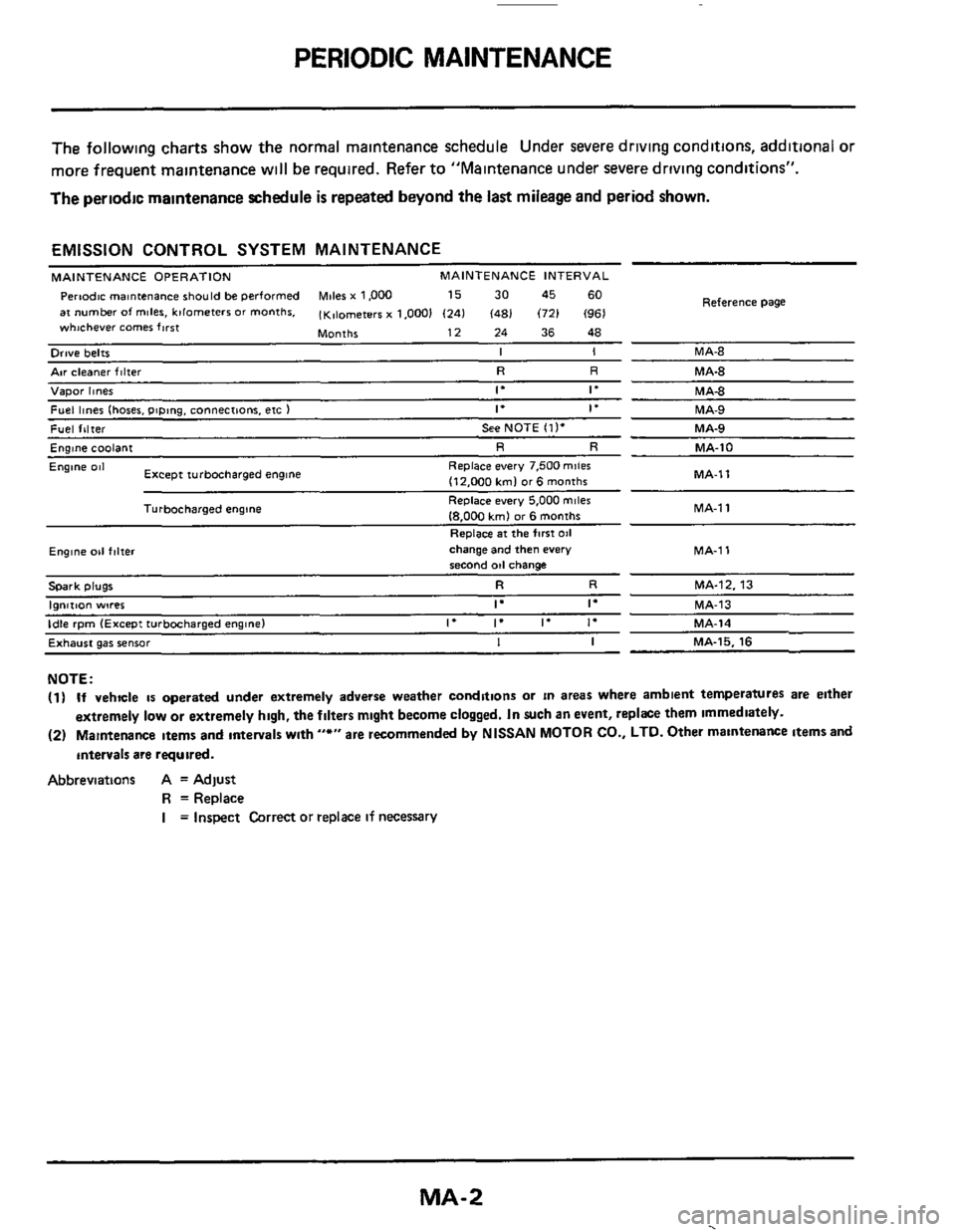
The following charts show the normal malntenance schedule Under severe driving conditions, additional or
more frequent maintenance
w~ll be required. Refer to "Maintenance under severe driving conditions".
The periodic maintenance schedule
is repeated beyond the last mileage and period shown.
EMISSION CONTROL SYSTEM MAINTENANCE
MAINTENANCE OPERATION MAINTENANCE INTERVAL
Pertodc rnantenance should be performed Miles x 1,000 15 30 45 60
at number of miles. kilometers or months. (K,lometerr x 1.0001 (241 (481 (721 (961
Months 12 24 36 48
whichever comer first
Reference
Page
Orwe belts I I MA-8
Air cleaner filter R R MA-8
Vapor hnes 1. If MA4
Fuel lines (hoses. piping. connections. etc ) If if MA-9
Fuel filter See NOTE (11. MA-9
Englne coolant R R MA-10
MA-1 1
Engine 081
MA-1
1
Replace every 7.500 mile6
(12.000 kml or6 months
Replace every 5,000
miles
18.000 kmJ or 6 months
Replace
at the first 011
Except turbocharged engine
Turbocharged engine
Ewne 011 f,lter change and then every MA-1 1 second od change
Spark plugs R R MA-12. 13
I"",..""
Exhaust gas sensor I I MA-15. 16
NOTE:
(1) If vehicle is operated under extremely adverse weather conditions or in areas where ambient temperatures are either
extremely
low or extremely high, the filters mlght become clogged. In such an event, replke them immediately.
(2) Maintenance Items and antervals wlth "*" are recommended by NISSAN MOTOR CO., LTD. Other maintenance items and
intervals
are required.
Abbreviations A = Adjust
R =Replace
I = Inspect Correct or replace if necessary
MA-2
.
Page 5 of 38
GENERAL MAINTENANCE
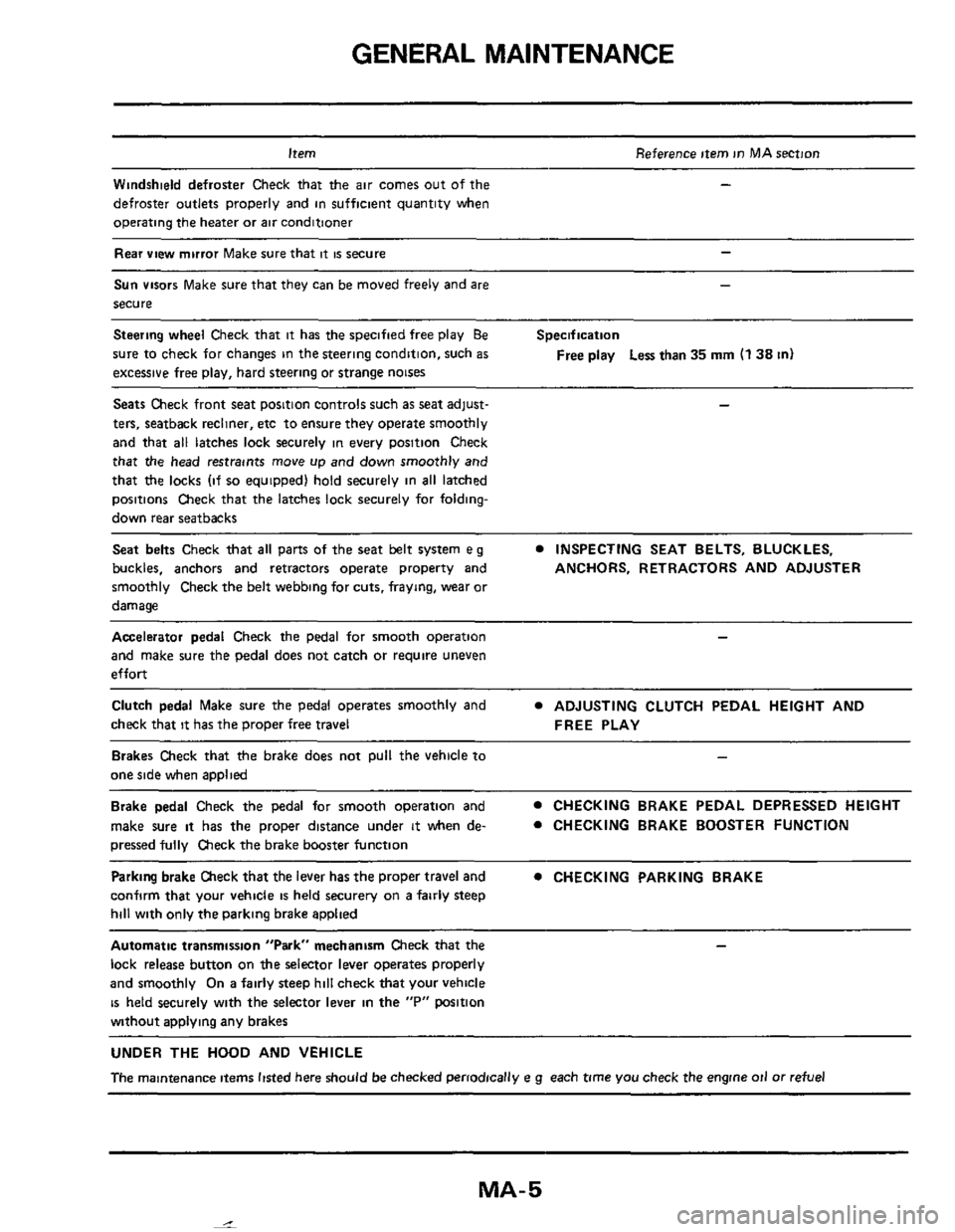
Item Reference item in MAsection
Windshield defroster Check that the air comes out of the
defroster outlets properly and in sufficient quantity when
operating the heater or
air conditioner
Rear view mirror Make sure that it is secure
-
-
Sun visors Make sure that they can be moved freely and are
secure
Steering wheel Check that it has the specified free play Be
sure to check for changes in the steering condition, such
as
excessive free play, hard steering or strange noises
-
Specification
Free
play Less than 35 mm (1 38 in)
Seats Check front seat position controls such as seat adjust- -
ters, seatback recliner, etc to ensure they operate smoothly
and that
all latches lock securely in every position Check
that the head restraints move up and down smoothly and
that
the locks (if so equipped) hold securely in all latched
positions Check that the latches lock securely for folding-
down rear seatbacks
Seat belts Check that all parts of the seat belt system e g
buckles, anchors and retractors operate property and ANCHORS, RETRACTORS AND ADJUSTER
smoothly Check the belt webbing for cuts, fraying, wear or
damage
INSPECTING SEAT BELTS, BLUCKLES,
Accelerator pedal Check the pedal for smooth operation -
and make sure the pedal does not catch or require uneven
effort
Clutch pedal Make sure the pedal operates smoothly and
check that
it has the proper free travel
ADJUSTING CLUTCH PEDAL HEIGHT AND
FREE PLAY
Brakes Check that the brake does not pull the vehicle to
one side when applied
Brake pedal Check the pedal for smooth operation and
make sure
it has the proper distance under it when de-
pressed fully Check the brake booster function
CHECKING BRAKE PEDAL DEPRESSED HEIGHT
0 CHECKING BRAKE BOOSTER FUNCTION
Parking brake Check that the lever has the proper travel and
confirm that your vehicle
is held securery on a fairly steep
hill with only the parking brake applied
0 CHECKING PARKING BRAKE
Automatic transmission "Park" mechanism Check that the
lock release button on the selector lever operates properly
and smoothly
On a fairly steep hill check that your vehicle
is held securely with the selector lever in the "P" wsition
without
aDDlvina anv brakes
UNDER THE HOOD AND VEHICLE
The maintenance items listed here should be checked periodically e g each time you check the engine oil or refuel
MA-5
Page 6 of 38
GENERAL MAINTENANCE
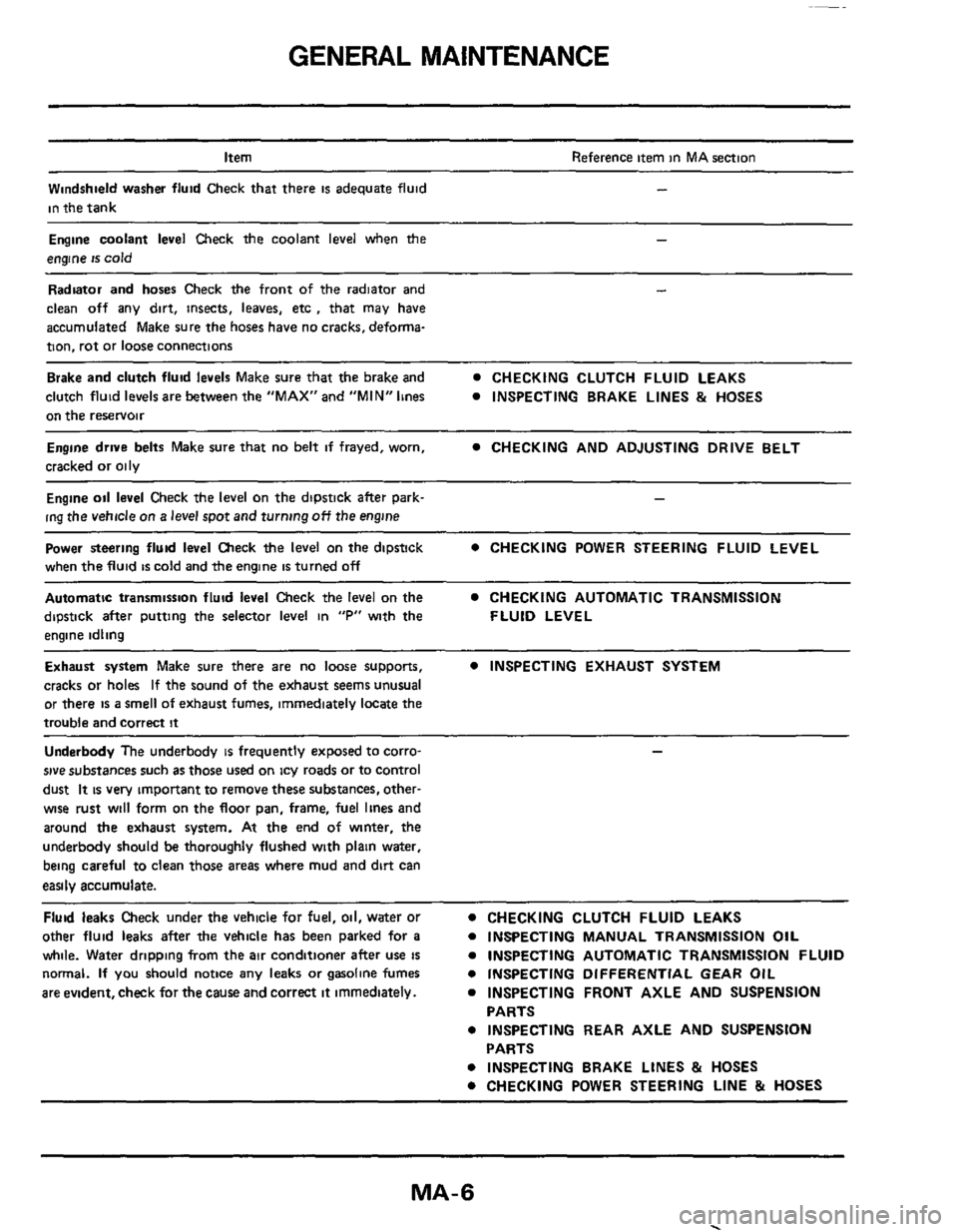
Item
Windshield washer fluid Check that there
is adequate fluid
in the tank
Reference item in MA section
-
Engine coolant level Check the coolant level when the -
engine is cold
Radiator and hoses Check the front of the radiator and
clean off any dirt, insects,
leaves, etc , that may have
accumulated Make sure the hoses have no cracks, deforrna-
tion, rot or loose connections
Brake and clutch fluid levels Make sure that the brake and CHECKING CLUTCH FLUID LEAKS
clutch fluid
levels are between the "MAX" and "MIN" lines INSPECTING BRAKE LINES & HOSES
on the reservoir
Engine drwe belts Make sure that no belt if frayed, worn,
cracked or oily CHECKING AND ADJUSTING DRIVE BELT
Engine oil level Check the level on the dipstick after park- -
ing the vehicle on a level spot and turning off the engine
Power steering fluid level Check the level on the dipstick
when the fluid
is cold and the engine is turned off
0 CHECKING POWER STEERING FLUID LEVEL
Automatic transmission fluid level Check the level on the CHECKING AUTOMATIC TRANSMISSION
dipstick after putting the selector
level in "P" with the FLUID LEVEL
engine idling
Exhaust system Make sure there are no loose supports, 0 INSPECTING EXHAUST SYSTEM
cracks or holes If the sound of the exhaust seems unusual
or there
is a smell of exhaust fumes, immediately locate the
trouble and correct
it
Underbody The underbody is frequently exposed to corro-
sive substances such as those used on icy roads or to control
dust
It is very impOrtant to remove these substances, other-
wise rust will form on the floor pan, frame, fuel lines and
around
the exhaust system. At the end of winter, the
underbody should be thoroughly flushed with plain water,
being careful to clean those
areas where mud and dirt can
easily accumulate.
Fluid leaks Check under the vehicle for fuel, oil, water or
other fluid
leaks after the vehicle has been parked for a 0 INSPECTING MANUAL TRANSMISSION OIL
while.
Water dripping from the air conditioner after use is 0 INSPECTING AUTOMATIC TRANSMISSION FLUID
normal. If you should notice
any leaks or gasoline fumes
are evident, check for
the cause and correct it immediately.
0 CHECKING CLUTCH FLUID LEAKS
0 INSPECTING DIFFERENTIAL GEAR OIL
0 INSPECTING FRONT AXLE AND SUSPENSION
0 INSPECTING REAR AXLE AND SUSPENSION
0 INSPECTING BRAKE LINES & HOSES
0 CHECKING POWER STEERING LINE & HOSES
PARTS
PARTS
MA-6
Page 8 of 38
ENGINE MAINTENANCE
Aw conditioner
compressor
Power steering oil pump
Applied pushing force
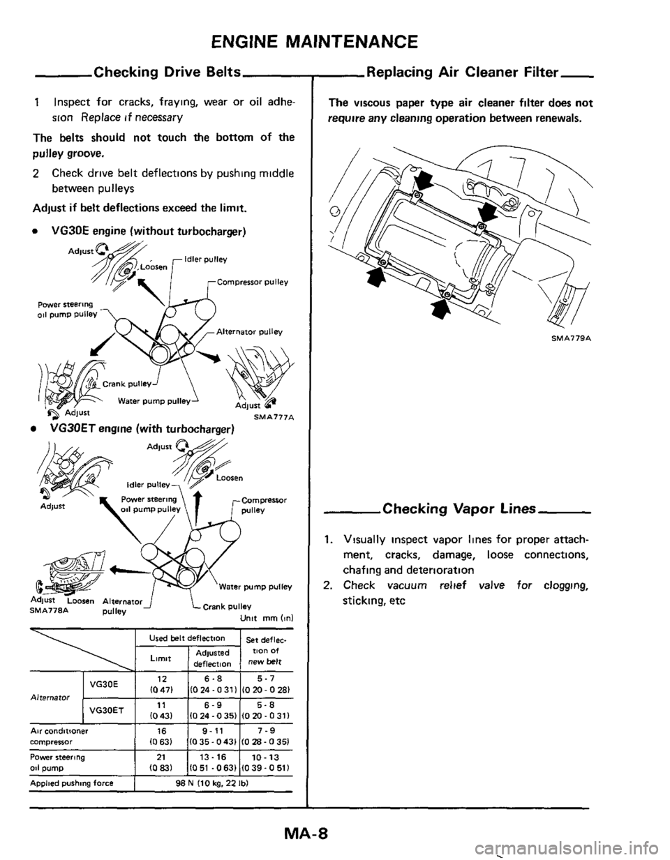
Checking Drive Belts
1 Inspect for cracks, fraying, wear or oil adhe-
sion Replace
if necessary
The belts should not touch
the bottom of the
pulley groove.
2
Adjust if belt deflections exceed the limit.
0 VG3OE engine (without turbocharger)
Check drive belt deflections by pushing middle
between pulleys
16 9-11 7-9
10 63) (0 35.0431 (0 28 - 0 351
21 13-16 10-13 (083) (051 -0631 (039-0511
98 N (10 kg. 22 Ibl
Power steering
Alternator pulley
Water pump pulle
SMA777A
VG30ET engine (with turbocharger)
Replacing Air Cleaner Filter-
The viscous paper type air cleaner filter does not
require any cleaning operation between renewals.
SMA779A
Checking Vapor Lines
1. Visually inspect vapor lines for proper attach-
ment, cracks, damage,
loose connections,
chafing and deterioration
2. Check vacuum relief valve for clogging,
sticking, etc
MA-8
Page 10 of 38
ENGINE MAINTENANCE
Changing Ei
WARNING:
To avoid the danger of being scalded, never
attempt to change the coolant when the engine
is hot.
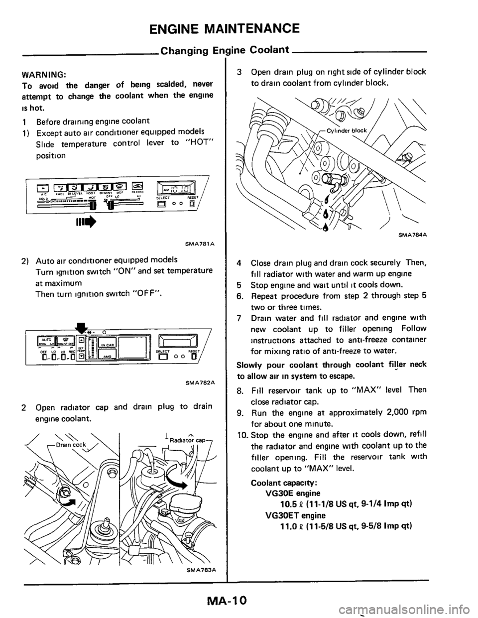
1 Before drainmg engine coolant
1) Except auto air conditioner equipped models
Slide temperature control lever to
"HOT"
position
SMAJ81 A
2) Auto air conditioner equipped models
Turn ignition switch
"ON" and set temperature
at maximum
Then turn ignition switch
"OFF".
SMA782A
2 Open radiator cap and drain plug to drain
engine coolant.
SMA703A
ine Coolant
3 Open drain plug on right side of cylinder block
to drain coolant from cylinder block.
4 Close drain plug and drain cock securely Then,
fill radiator with water and warm up engine
5 Stop engine and wait until it cools down.
6. Repeat procedure from step 2 through step 5
two or three times.
7 Drain water and fill radiator and engine with
new coolant up to
filler opening Follow
instructions attached to anti-freeze container
for
mixing ratio of anti-freeze to water.
Slowly pour coolant through coolant fryer neck
to allow air in system to escape.
8. Fill reservoir tank up to "MAX" level Then
close radiator cap.
9. Run the engine at approximately 2,000 rpm
for about one minute.
IO. Stop the engine and after it cools down, refill
the radiator
and engine with coolant up to the
filler opening. Fill the reservoir tank with
coolant up to "MAX" level.
Coolant capacity:
VG30E engine
VG30ET engine
10.5 P (11-1/8 US qt, 9-1/4 Imp qt)
11.0 P (1 1-5/8 US qt, 9-5/8 Imp qt)
MA-1 0
Page 14 of 38
ENGINE MAINTENANCE
Checking idle Speed (VG30E engine)
Preparation
WARNING:
a. Depress brake pedal while accelerating the engine to prevent forward surge of vehicle.
b. Inspection should
be carried out while shift lever IS in "D" position on automatic transmission equipped
models.
c. After inspection and adjustment have been made, shift the lever to "N" or "P" position.
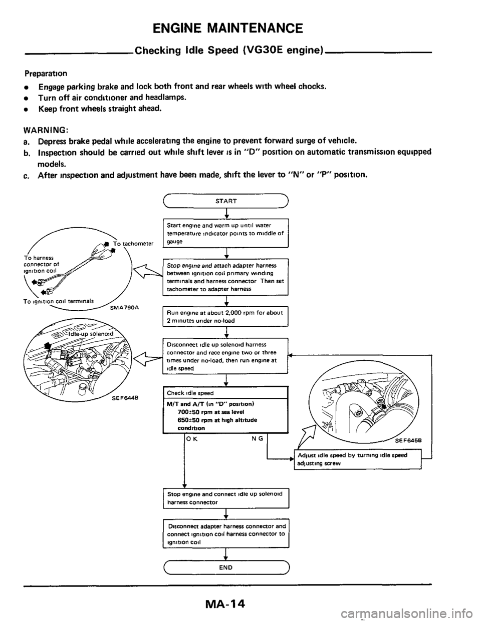
Engage parking brake and lock both front and rear wheels with wheel chocks.
Turn
off air conditioner and headlamps.
Keep front wheels straight ahead.
c START I 1
Start engine and warm up untgl water
temperature Indicator poinrs to middle of
I
To harness 4
Stop engine and anach adapter harness between ignmon coil primary winding terminals and harness connector Then set
timer under no-load, then run engine at
+
Stop engine and connect idle UP solenoid
harness connector
Dismnnm adapter harness Connector and
connect ignition
coil harness connector io
(- END
MA-I 4
-
Page 28 of 38
CHASSIS AND BODY MAINTENANCE
Checking Parking Brake
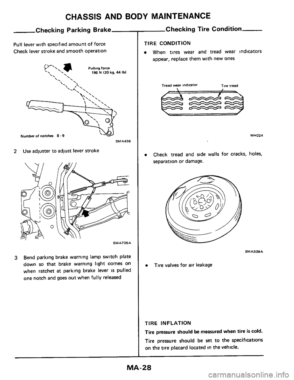
Pull lever with specified amount of force
Check lever stroke and smooth operation
Pullmg force . 196 N I20 kg. 44 Ibl
\' \ \' '
Number of notches 8 -9
SMA436
2 Use adjuster to adjust lever stroke
SMAl35A
3 Bend parking brake warning lamp switch plate
down
so that brake warning light comes on
when ratchet
at parking brake lever IS pulled
one notch and goes out when
fully released
Checking Tire Condition
TIRE CONDITION
0 When tires wear and tread wear indicators
appear, replace them with new ones
Tread wear indicaror Tire iread
WHO24
0 Check tread and side walls for cracks, holes,
separation or damage.
SMAS39A
0 Tire valves for air leakage
TIRE INFLATION
Tire
pressure should be measured when tire is cold.
Tire pressure should be
set to the specifications
on the tire placard located in the vehicle.
Page 32 of 38
CHASSIS AND BODY MAINTENANCE
Balancing Wheels
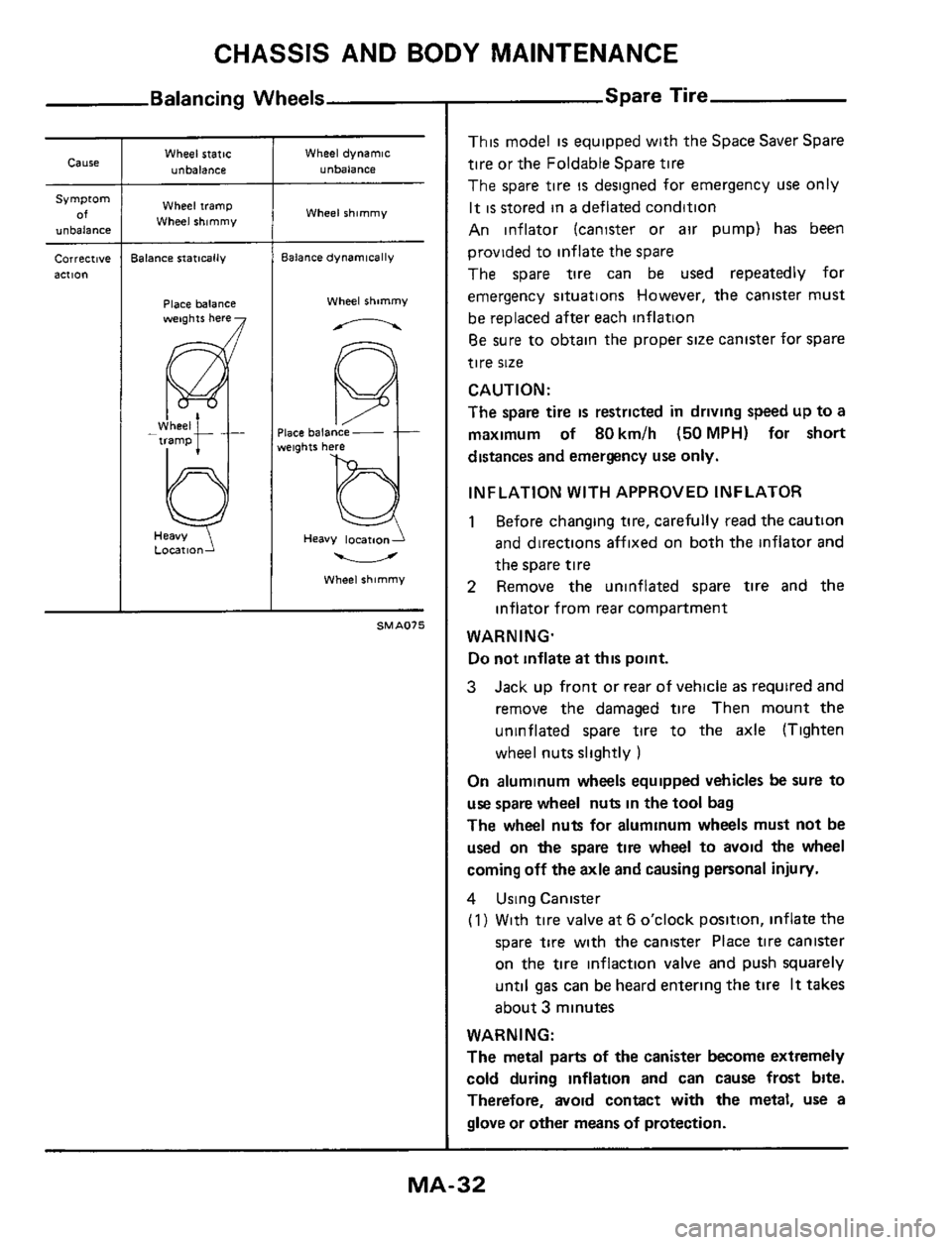
Cause
Symptom
of unbalanci
correct,vt
action
Wheel static
unbalance
Wheel tramp
Wheel shimmy
lalance statically
Place balance weights here
L0CatlO"J
Wheel dynamic
unbalance
Wheel shimmy
Balance dynamically
Wheel shimmy
n
Heavy locatnoni
u
Wheel shimmy
SMAO7S
Spare Tire
This model is equipped with the Space Saver Spare
tire or the Foldable Spare tire
The spare tire
is designed for emergency use only
It
IS stored in a deflated condition
An inflator (canister or air pump) has been
provided to inflate the spare
The spare tire can be used repeatedly for
emergency situations However, the canister must
be replaced after each inflation
Be sure to obtain the proper size canister for spare
tire
size
CAUTION:
The spare tire
is restricted in driving speed up to a
maximum
of 80km/h (50MPH) for short
distances and emergency use only.
INFLATION WITH APPROVED INFLATOR
1 Before changing tire, carefully read the caution
and directions affixed on both the inflator and
the spare tire
2 Remove the uninflated spare tire and the
inflator from rear compartment
WARNING. Do not inflate at
this point.
3 Jack up front or rear of vehicle as required and
remove the damaged
tire Then mount the
uninflated spare
tire to the axle (Tighten
wheel nuts slightly
)
On aluminum wheels equipped vehicles be sure to
use spare wheel nuts in the tool bag
The wheel nuts for aluminum wheels must not be
used on the spare tire wheel to avoid the wheel
coming off the axle and causing personal injury.
4 Using Canister
(1) With tire valve at 6 o'clock position. inflate the
spare tire with the canister Place tire canister
on the
tire inflaction valve and push squarely
until
gas can be heard entering the tire It takes
about
3 minutes
WARNING:
The metal parts of the canister become extremely
cold during inflation and can cause frost bite.
Therefore, avoid contact with the metal, use a
glove or other means
of protection.
MA-32