Page 14 of 38
ENGINE MAINTENANCE
Checking idle Speed (VG30E engine)
Preparation
WARNING:
a. Depress brake pedal while accelerating the engine to prevent forward surge of vehicle.
b. Inspection should
be carried out while shift lever IS in "D" position on automatic transmission equipped
models.
c. After inspection and adjustment have been made, shift the lever to "N" or "P" position.
Engage parking brake and lock both front and rear wheels with wheel chocks.
Turn
off air conditioner and headlamps.
Keep front wheels straight ahead.
c START I 1
Start engine and warm up untgl water
temperature Indicator poinrs to middle of
I
To harness 4
Stop engine and anach adapter harness between ignmon coil primary winding terminals and harness connector Then set
timer under no-load, then run engine at
+
Stop engine and connect idle UP solenoid
harness connector
Dismnnm adapter harness Connector and
connect ignition
coil harness connector io
(- END
MA-I 4
-
Page 15 of 38
ENGINE MAINTENANCE
Checking Exhi
48,000 krn (30,000 miles) OR 24 MONTHS
SERVICE
Exhaust gas sensor should be checked after 48,000
km (30,000 miles) or 24 months of operation
After vehicle has been operated for
48,000 km
(30,000 miles), exhaust gas sensor warning lamp
will come on to indicate that sensor should
be
inspected
Digital type
t
After inspection, disconnect warning lamp harness
connector so that warning lamp will not come on
thereafter.
SMA792A
1st Gas Sensor
MA-1 5
.-I
Page 16 of 38
ENGINE MAINTENANCE
Checking Exhaust Gas Sensor (Cont'd)
Preparation
When checking exhaust gas sensor, make sure that the following are
in good order
0 Battery
0 Hoses
Engine oil and coolant levels
E C C S. components
E.C C S. harness and connectors
Oil filler cap and oil level gauge
Checking procedure
START
Stan engine and warm UP until water
temperature indicator Points
IO middle
of gauge
I +
Run engine at about 2.000 rpm for abut
2 minutes under noload
I
E C C S control unit is turned fully
referring to MIXTURE RA
MA-1 6
Page 18 of 38
CHASSIS AND BODY MAINTENANCE
Checking Clutch System
Check clutch fluid lines for proper attachment,
leaks, chafing, deterioration, etc
SMA741A
Checking M/T Oil
1. Check manual transmission for signs of leakage
SMA429A
2 Check oil level
LFiller plug
SMAl03
Never start engine while checking oil level.
Changing M/T Oil
n
Drain plug
Oil capacity:
FS5W71C and BW T-5 (FS5R90A)
1.9 Liters (4 US pt, 3-3/8 Imp pt)
MA-1 8
Page 19 of 38
CHASSIS AND BODY MAINTENANCE
1 Check automatic transmission for signs of
leakage
SMA430A
2 Check under following conditions
(1) Place selector lever in "P" (PARK) position
and
idle engine
(2) Maintain fluid temperature at 50 to 80°C
(122 to 176'F)
(3) Add oil, if necessary
Use only A/T fluid having "DEXRON"
SMA559A
L/T Fluid
3 Check automatic fluid condition.
Check fluid for contamination to determine
condition of automatic transmission If fluid
is very dark or smells burned, the frictional
material (clutches, band,
etc ) may need re-
placement
Check flwd for COntaminarlOn
r?
,w
Check fluid for smell SMA107
MA-19
Page 23 of 38

CHASSIS AND BODY MAINTENANCE
Checking Rear Axle and
Rear Suspension Parts (Cont'd)
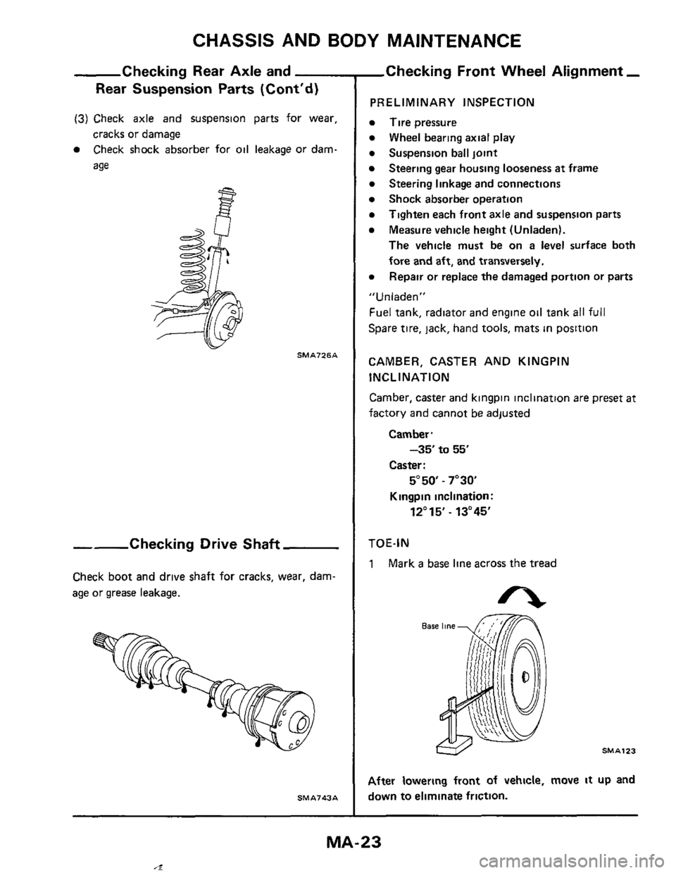
(3) Check axle and suspension parts for wear,
cracks or damage
0 Check shock absorber for oil leakage or dam-
age
- SMA726A
--Checking Drive Shaft
Check boot and drive shaft for cracks, wear, dam-
age or grease leakage.
SM A743 A
,Checking Front Wheel Alignment -
PRELIMINARY INSPECTION
Tire pressure
Wheel bearing axial play
Suspension ball joint
Steering linkage and connections
Shock absorber operation
Tighten each front axle and suspension parts
Measure vehicle height (Unladen).
The vehicle must be on a level surface both
fore and
aft, and transversely.
Repair or replace the damaged portion or
parts
Steering gear housing looseness at frame
" U n I aden "
Fuel tank, radiator and engine oil tank all full
Spare tire, lack, hand tools, mats in position
CAMBER, CASTER AND KINGPIN
INCLINATION
Camber, caster and kingpin inclination are preset
at
factory and cannot be adjusted
Camber.
-35 to 55'
Caster :
5"50 - 7"3Q
Kingpin inclination:
12"15' - 13"45'
TOE-IN
1 Mark a base line across the tread
After lowering front of vehicle, move it up and
down
to eliminate friction.
MA-23
4
Page 25 of 38
CHASSIS AND BODY MAINTENANCE
Checking Rear
PRELIMINARY INSPECTION
0 Tire pressure.
0 Wheel bearing axial play
0 Shock absorber operation.
0
0 Measure vehicle height (Unladen)
Tighten each rear axle and suspension part
The vehicle must be on a level surface both
fore and
aft, and laterally
Repair or replace the damaged portion or parts
0
"Unladen"
Fuel tank, radiator and engine oil tank all full
Spare
tire, jack, hand tools, mats in position
CAMBER
Camber
is preset at factory and cannot be adjusted
Camber:
-1"55'tO -25'
TOE-IN
1. Mark a base line across the tread
SMA123
nee1 Alignment
2 Measure toe-in
~~ner parallel to center Ime of body-
Toe-in = A - B
, Front 8 SMA124
Toe-in:
-2 to 2 mm (-0.08 to 0.08 in)
3 Toein can be adjusted by inside of rear arm
bushing pins
Unit
Tobl" TObOltl Max 9 6 10 3781 Max 9.6 (0.378)
When performing toe adjustment, always set the
cams in the same position on the right and left rear
arm bushing pins.
MA-25
,,_l
Page 33 of 38

CHASSIS AND BODY MAINTENANCE
Spare Til
(2) To ensure complete emptying of the canister,
hold the canister in position for one minute
after sound stops
If temperature is below -10°C (14OF), the
canister must be warmed on
the windshield
defroster for five to ten minutes to provide
tire
inflation
b. In cold weather, the tire may not look fully
.inflated Therefore, drive slowly for the
first
mile, as the tire temperature rises the pressure
will mcrease.
a
Using Air Compressor
(1) Remove the valve cap from the spare tire and
securely connect the air pump hose in
its place
(2) Connect the power cord plug of the air pump
to the cigarette lighter socket The spare
tire
may be inflated to the recommended pressure
28 psi (200 kPa) in about 6 minutes Adjust
the
tire pressure per the tire placard with tire
pressure gauge
If the air pump operation is slow, run the engine
while the air pump is operating In this case,
remove jack with
the spare tire attached to the
axle.
WARNING:
0
0
Do not run the engine in closed space or with
the car being jacked up
Do not touch the air pump with the bare hands
while
it is operating for it may become quite
hot.
(3) Disconnect the power cord plug from socket
Check the
tire for air leakage, and then
securely install and tighten the valve cap
5 Lower car and fully tighten wheel nuts
Do not
install the wheel cover on the spare tire
DEFLATION
1 Deflate tire by depressing button on tire
inflation valve or by removing valve core
WARN1 NG.
To avoid personal injury, do not inhale the
gas
which is vented while the tire is deflating.
(Cont'd)
2 Flatten tire The spare tire becomes folded
3
REPAIR
Only qualified tire experts are authorized to
dismount the spare tire from
its rim or repair it in
any way Improper service can result
in serious
personal injury
Contact aumorized B.F. Goodrich dealers (for
Space Saver Spare tire)
or authorized Bridgestone
or DATSUN dealers (for Foldable Spare tire)
if
setvice is required.
iqradually while deflating
Store tire in rear compartment
MA-33