1984 NISSAN 300ZX oil
[x] Cancel search: oilPage 1 of 38
HEATER &
AIR CONDITIONER
I v __I_--
SECTION HA^ I
CONTENTS
GENERAL DESCR I PTlON . ... .. . HA- 2
AIR FLOW AND COMPONENT LAYOUT
. .. . .. HA- 3
DOOR CONTROL .. 1.. .. HA- 6
LOCATION OF VACUUM COMPONENTS ... HA- 5
HEATER ELECTRICAL CIRCUIT. . . . . .. HA- 7
DESCRIPTION-Air Conditioner (Manual) . ... ..
A/C PERFORMANCE TEST ..
DISCHARGING, EVACUATING, CHARGING AND CHECKING
PRECAUTIONS FOR REFRIGERANT CONNECTION .
PIPING, COMPRESSOR MOUNTING AND F.1 C D.
COMPRESSOR OIL-ForMJS170
. . .. ..
COMPRESSOR-Model MJS170 .. ..
A/C ELECTRICAL CIRCUIT (Manual) . .. ..
A/C ELECTRICAL COMPONENTS (Manual) ..
LOCATION OF A/C ELECTRICAL COMPONENTS ....
SERVICE DATA AND SPECIFICATIONS (S D S ) . .
SPECIAL SERVICE TOOLS .. ..
HA- 9
HA-12
HA-18
HA-20
. HA-21
HA-23
HA-25
. HA-30
.. HA-32
. HA-34
.. HA-35
. HA-38
Page 12 of 38
DISCHARGING, EVACUATING, CHARGING AND CHECKING
Precautions
WARNING:
Always be careful that refrigerant does not
come in contact with your skin.
Always wear
eye protection when working
around the
system
Keep refrigerant containers stored below 50°C
(122" F) and never drop it from a high place
Work
in well-ventilated area because refrigerant
gas evaporates quickly and breathing may be-
come difficult due to the lack of oxygen
Keep refrigerant away from open flames
be-
cause poisonous gas will be produced if it is
burns.
Do not use steam to clean surface of condenser
or evaporator
Be sure to use cold water or
compressed air.
Compressed
air must never be used to clean a
dirty line Clean with refrigerant gas
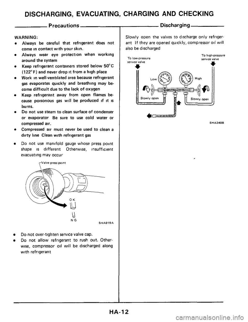
Do not use manifold gauge whose press point
shape
is different Otherwise, insufficient
evacuating may occur
fJalve press point
NG SHA919A
Do not over-tighten service valve cap.
Do not allow refrigerant to rush out. Other-
wise, compressor oil will
be discharged along
with refrigerant
Discharging
Slowly open the valves to discharge only refriger-
ant If they
are opened quickly, compressor oil will
also be discharged
To low-pressure IerYlCe valve
To high-pressure service valve
*
SHA240B
4c==--J
HA-I 2
Page 17 of 38
DISCHARGING, EVACUATING, CHARGING AND CHECKING
ELECTRIC L EAK-DETECTOR
The leak detector IS a delicate device that detects
small amounts of halogen
In order to
use the device properly, read the
manuals
put out by each maker and perform the
specified maintenance and inspections
Nominal senmivity 15.25 g (0 53.0 88 ozllvear
.. SHA733A
GENERAL PRECAUTIONS FOR HANDLING
LEAK DETECTOR
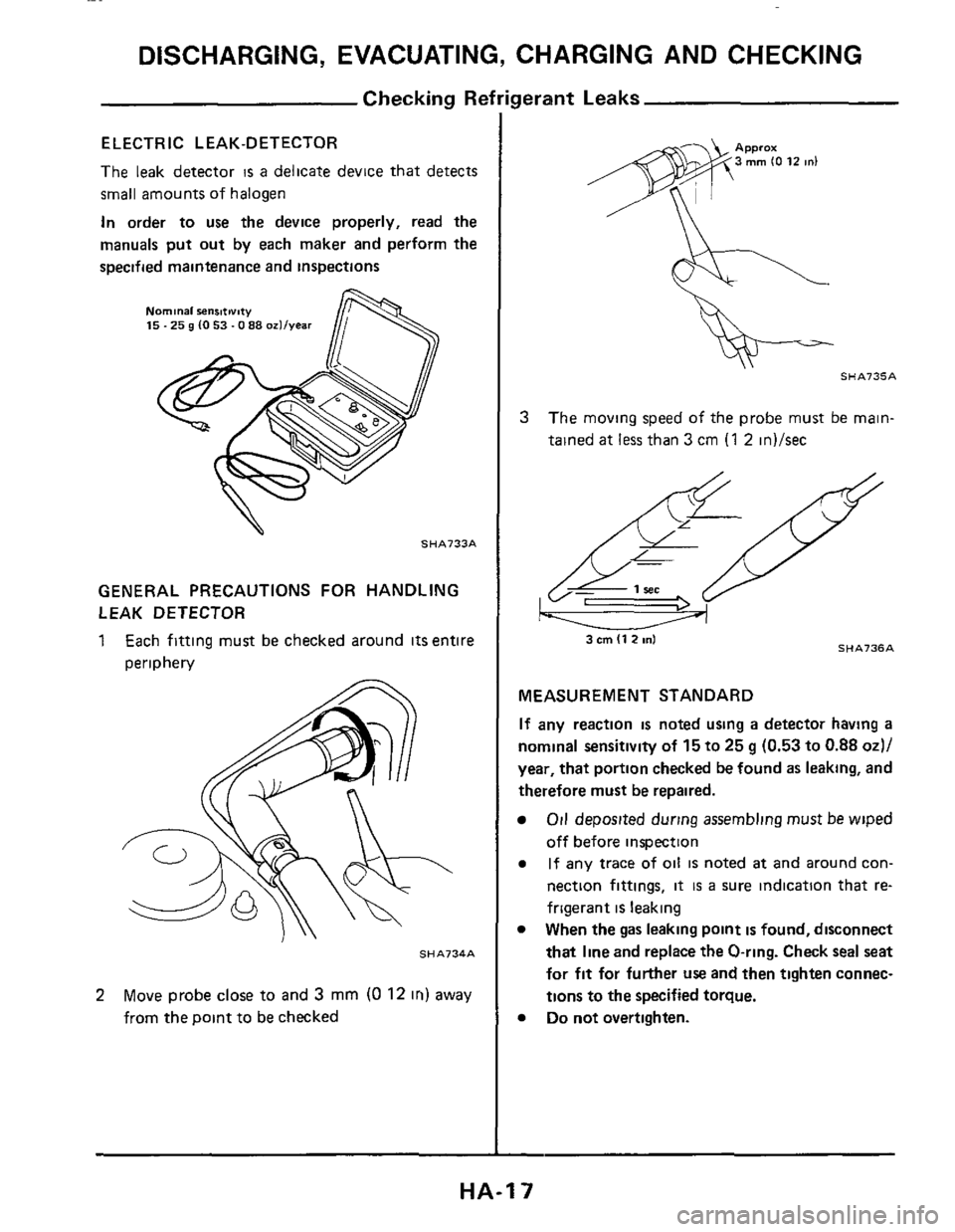
1 Each fitting must be checked around its entire
periphery
SHA734A
2 Move probe close to and 3 mm (0 12 in) away
from the point to be checked
SHA735A
3 The moving speed of the probe must be main-
tained
at less than 3 cm (1 2 in)/sec
SHA736A 3 cm (1 2 ml
MEASUREMENT STANDARD
If any reaction is noted using a detector having a
nominal sensitivity of 15 to 25 g (0.53 to 0.88 od/
year, that portion checked be found as leaking, and
therefore must be repaired.
Oil deposited during assembling musr be wiped
off before inspection
If any trace of oil is noted at and around con-
nection fittings,
it is a sure indication that re-
frigerant
is leaking
When the
gas leaking point is found, disconnect
that line and replace
the O-ring. Check seal seat
for fit for further use and then tighten connec-
tions
to the specified torque.
Do not overtighten.
HA-I 7
Page 20 of 38
PRECAUTIONS FOR REFRIGERANT CONNECTION
WARNING.
Gradually loosen discharge side hose fitting, and re-
move
it after remaining pressure has been released
When replacing or cleaning refrigerant cycle com-
ponents, observe the following
Do not leave compressor on its side or upside
down for more than 10 minutes, as compressor
oil will enter low pressure chamber
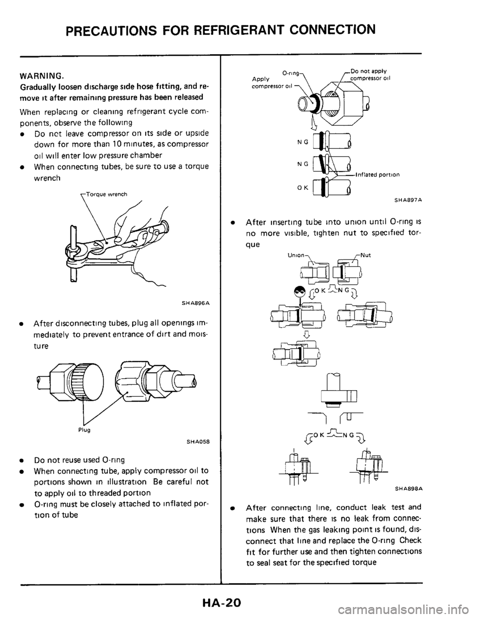
When connecting tubes, be sure to
use a torque
wrench
torque wrench
SHA896A
After disconnecting tubes, plug all openings im-
mediately to prevent entrance of dirt and mois-
tu
re
Plug
SHA058
Do not reuse used O-ring
When connecting tube, apply compressor oil to
portions shown in illustration
Be careful not
to apply oil to threaded portion
O-ring must be closely attached to inflated por-
tion of tube
NG
lnflaied pomon
OK - SHA897A
After inserting tube into union until O-ring is
no more visible, tighten nut to specified tor-
que
u"'06a e GO K GN G 7
b
SHA898A
After connecting line, conduct leak test and
make sure that there
IS no leak from connec-
tions When the
gas leaking point IS found, dis-
connect that line and replace the O-ring Check
fit for further use and then tighten connections
to seal seat for the specified torque
HA-20
Page 23 of 38
COMPRESSOR OIL--For MJS170
Checking and Adjusting
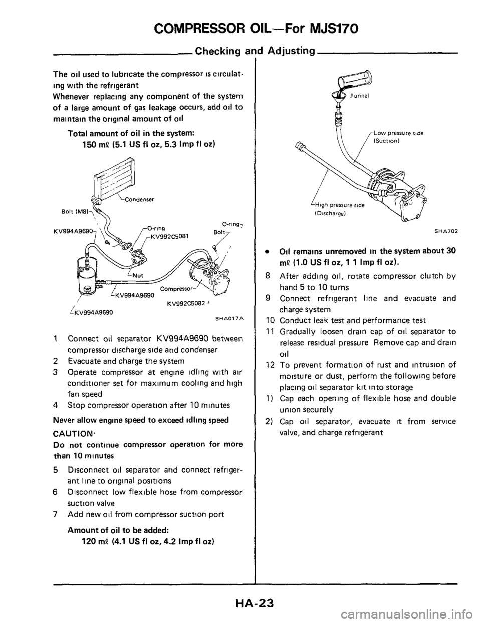
The oil used to lubricate the compressor is circulat-
ing with the refrigerant
Whenever replacing any component of the system
of
a large amount of gas leakage occurs, add oil to
maintain the original amount
of oil
Total amount of oil in the system:
150 mP (5.1 US fl 02, 5.3 Imp fl 02)
KV994A9690
KV992C50822 /
i;(V994A9690 SHAO17A
1
2
3
Connect oil separator KV994A9690 between
compressor discharge
side and condenser
Evacuate and charge the system
Operate compressor
at engine idling with air
conditioner
set for maximum cooling and high
fan speed
4 Stop compressor operation after 10 minutes
Never allow engine speed to exceed idling speed
CAUTION.
Do not continue compressor operation for more
than 10 minutes
5 Disconnect oil separator and connect refriger-
ant line
to original positions
6 Disconnect low flexible hose from compressor
suction
valve
7 Add new oil from compressor suction port
Amount of oil to be added:
120 mP (4.1 US fl oz,4.2 Imp fl 02)
Low pressure ride
SHA702
0 Oil remains unremoved in the system about 30
mP (1.0 US fl 02, 1 1 Imp fl 02).
8 After adding oil, rotate compressor clutch by
hand 5 to 10 turns
9 Connect refrigerant line and evacuate and
charge system
10 Conduct leak
test and performance test
11 Gradually loosen drain cap of oil separator to
release residual pressure Remove cap and drain
Oil
12 To prevent formation of rust and intrusion of
moisture or dust, perform the following before
placing oil separator kit into storage
1) Cap each opening of flexible hose and double
union securely
2) Cap oil separator, evacuate it from service
valve, and charge refrigerant
HA-23
Page 24 of 38
COMPRESSOR OIL-For MJS170
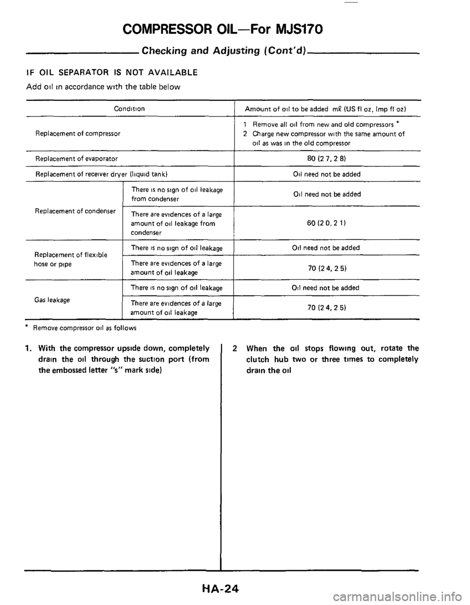
Condition Amount of oil to be added mP IUS fl 02. Imp fl 02)
Replacement of compressor
Replacement of evaporator
Replacement
of receiver drver (liquid tank)
There is no sign of oil leakage
from condenser
1 Remove all oil from new and old compressors *
2 Charge new compressor with the same amount of
oil as was in the old compressor
80 (2 7,2 8)
Oil need not be added
Oil need not be added
Replacement Of ‘Ondenser There are evidences of a large
amount of
oil leakage from
condenser 60 (2 0.2 1)
There is no sign of oil leakage
There are evidences of a large
amount of
oil leakage 70 (2 4, 2 5) hose or pipe
Oil need not be added
There is no sign of oil leakage
There are evidences
of a large
amount
of oil leakage
Gas leakage
* Remove compressor oil as follows
1. With the compressor upside down, completely
drain the
oil through the suction port (from
the embossed letter
“s” mark side)
Oil need not be added
70 I2 4, 2 5)
2 When the oil stops flowing out, rotate the
clutch hub
two or three times to completely
drain the
oil
HA-24
Page 27 of 38
COMPRESSOR-Model MJS170
Shaft Seal Replacement
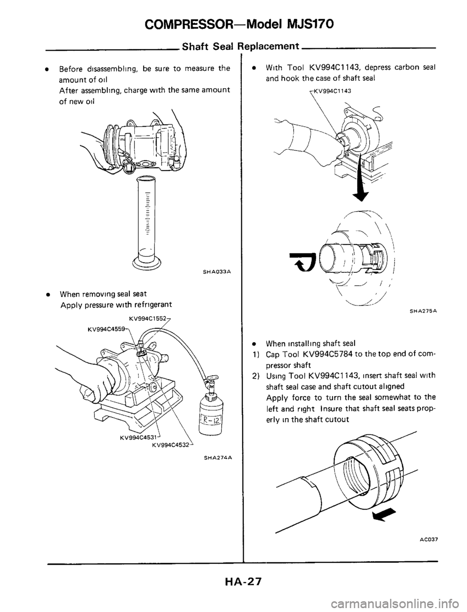
Before disassembling, be sure to measure the
amount of
oil
After assembling, charge with the same amount
of new oil
When removing seal seat
Apply pressure with refrigerant
KV994C15527
SHA033A
SHA274A
0 With Tool KV994C1 143, depress carbon seal
and hook the case of shaft seal
yKV994C1143
0 When installing shaft seal
1) Cap Tool KV994C5784 to the top end of corn-
pressor shaft
2) Using Tool KV994C1 143, insert shaft seal with
shaft
seal case and shaft cutout aligned
Apply force to turn the
seal somewhat to the
left and right insure that shaft seal seats prop-
erly in the shaft cutout
AC037
HA-27
Page 35 of 38
SERVICE DATA AND SPECIFICATIONS (S. D. S.)
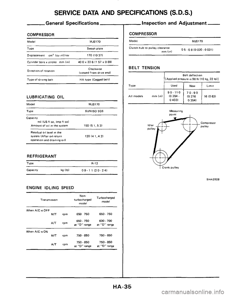
General Specifications
COMPRESSOR
Model MJS170
Type Swash plate
Displacement
cm' lcu mllrev 170 110371
Cvllnder bore x stroke mm linl 40 0 x 22 6 I1 57 x 0 891
Clockwse
(viewed
from drive end1 Direcrion of rotafion
Type of driving belt HA type [Cogged belt1
LUBRICATING OIL
Model MJSl70
Type SUNISO 5GS
Capacitv
mP IUS fl OT, Imp fl OLI
Amount Of 011 in the system
Residual 011 level in the
operation and draining
0811
150 15 1.5 31
ryrrem (After 011 return 120141.421
REFRIGERANT
Type R-12
Capacity kg IIbI 09-1 1120-241
ENGINE IDLING SPEED
Non-
model
Turbocharged
model Traosmt6iton turbocharged
When AJC IS OFF MIT rpm 650 750 650 - 750
650 - 750 600.700
'pm at "D', range at "D" range
When AIC 81 ON MIT rpm 750-850 750 - 850
750.850 750.850
'IT at "D" range at "D" range
--Inspection and Adjustment -
COMPRESSOR
Model MJS170
0 5 -0 8 I0020 -00311 Clutch hub to pulley clearance mm lml ~~
BELT
TENSION
Belt deflection I [Apploed Pressure 1s 98 N I10 kg, 22 Ibll
0 4331 0 3541
SHA252B
HA-35