Page 19 of 38

A/C PERFORMANCE TEST
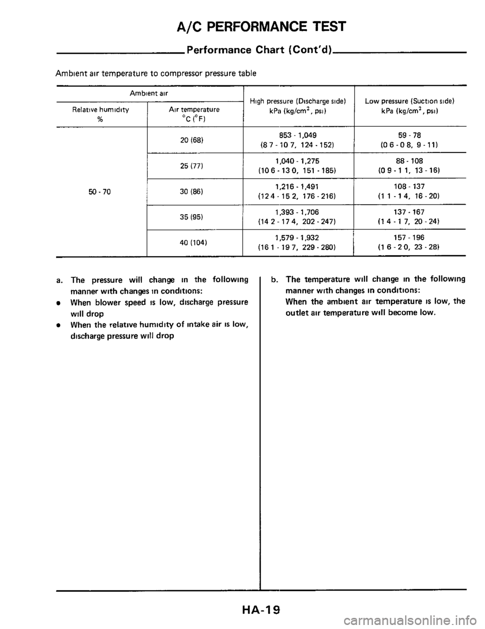
Ambient air
Relative humidity Air temperature
% OC (OF)
20 (68)
Performance Chart (Cont’d)
High pressure (Discharge side)
kPa (kg/cm2,
psi)
Low pressure (Suction side)
kPa (kg/cm’, psi)
853 - 1,049 59 - 78
(87-107. 124-1521 (06-08. 9-11)
Ambient air temperature to compressor pressure table
I I
1,040.1,275 88.108 ~
25(771
(10 6 - 13 0, 151 - 185) (09-1 1. 13-16)
50.70 I I
1,216- 1,491 108 - 137
(124-152, 176-216) (1 1 .14, 16.20) 1 30(86)
I I
1,393 - 1,706 137.167
(14 2 - 174, 202 - 247) (14-17. 20-24)
I I
1,579 - 1,932
(161 -197, 229-280) 157 - 196
(1
6 - 2 0, 23 - 28) I 40(104)
a. The pressure will change in the following
manner with changes in conditions:
When blower speed is low, discharge pressure
will drop
When the relative humidity of intake air IS low,
discharge pressure will drop
b. The temperature will change in the following
manner with changes
in conditions:
When the ambient air temperature
IS low, the
outlet air temperature will become low.
HA-I 9
Page 22 of 38

PIPING, COMPRESSOR MOUNTING AND F.I.C.D.
Idle Speed Adju
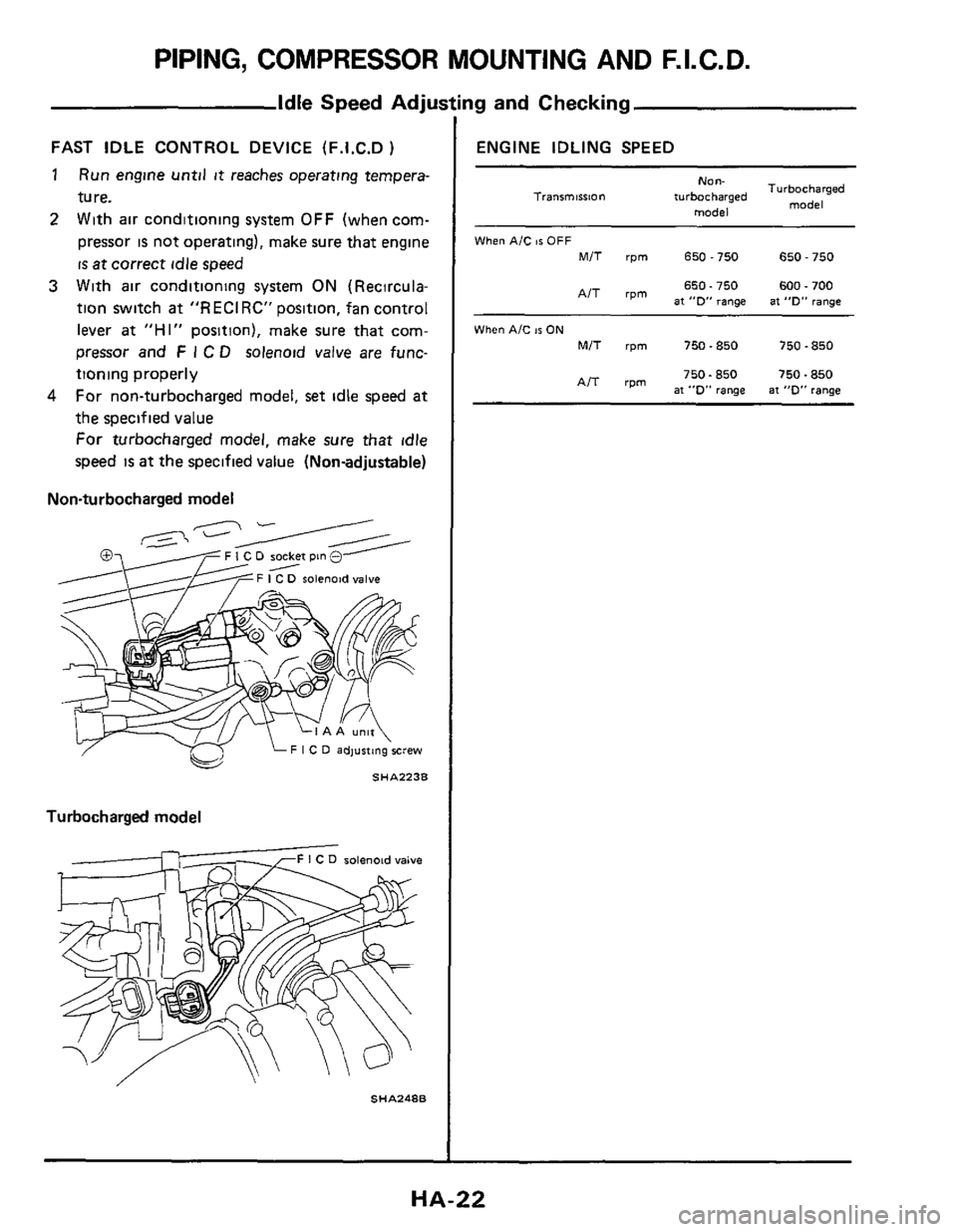
FAST IDLE CONTROL DEVICE (F.1.C.D )
1
2
Run engine until it reaches operating tempera-
ture.
With air conditioning system
OFF (when com-
pressor
is not operating), make sure that engine
is at correct idle speed
3 With air conditioning system ON (Recircula-
tion switch
at "RECIRC" position, fan control
lever
at "HI" position), make sure that com-
pressor and
F I C D solenoid valve are func-
tioning properly
For non-turbocharged model,
set idle speed at
the specified value
For turbocharged model, make sure that idle
speed is at the specified value (Nonadjustable)
4
Non-turbocharged model
F I C D socket pin 0
solenoid valve
Turbocharged model
solenoid valve
SHA248B
ng and Checking
ENGINE IDLING SPEED
NO"-
model
Turbocharged
model Tranrmission turbocharged
When AIC 86 OFF
MIT rpm 650-750 650 - 750
650.750 600.700 AIT rpm at "0" range at "D" range
When AIC IS ON
MIT rpm 750-850 750 - 850
750.850 750.850 AIT rpm at "D" range at "0" range
HA-22
Page 23 of 38

COMPRESSOR OIL--For MJS170
Checking and Adjusting
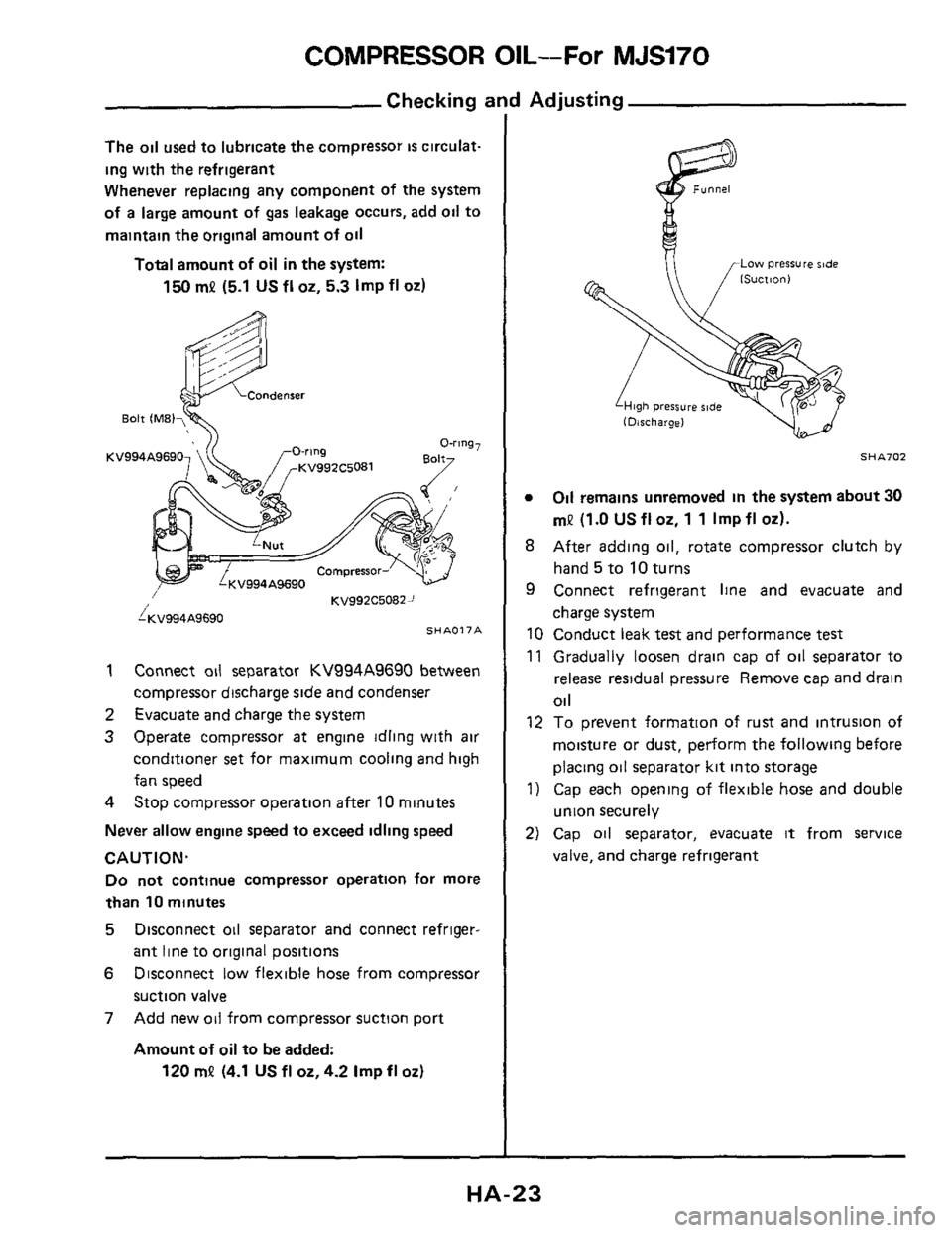
The oil used to lubricate the compressor is circulat-
ing with the refrigerant
Whenever replacing any component of the system
of
a large amount of gas leakage occurs, add oil to
maintain the original amount
of oil
Total amount of oil in the system:
150 mP (5.1 US fl 02, 5.3 Imp fl 02)
KV994A9690
KV992C50822 /
i;(V994A9690 SHAO17A
1
2
3
Connect oil separator KV994A9690 between
compressor discharge
side and condenser
Evacuate and charge the system
Operate compressor
at engine idling with air
conditioner
set for maximum cooling and high
fan speed
4 Stop compressor operation after 10 minutes
Never allow engine speed to exceed idling speed
CAUTION.
Do not continue compressor operation for more
than 10 minutes
5 Disconnect oil separator and connect refriger-
ant line
to original positions
6 Disconnect low flexible hose from compressor
suction
valve
7 Add new oil from compressor suction port
Amount of oil to be added:
120 mP (4.1 US fl oz,4.2 Imp fl 02)
Low pressure ride
SHA702
0 Oil remains unremoved in the system about 30
mP (1.0 US fl 02, 1 1 Imp fl 02).
8 After adding oil, rotate compressor clutch by
hand 5 to 10 turns
9 Connect refrigerant line and evacuate and
charge system
10 Conduct leak
test and performance test
11 Gradually loosen drain cap of oil separator to
release residual pressure Remove cap and drain
Oil
12 To prevent formation of rust and intrusion of
moisture or dust, perform the following before
placing oil separator kit into storage
1) Cap each opening of flexible hose and double
union securely
2) Cap oil separator, evacuate it from service
valve, and charge refrigerant
HA-23
Page 33 of 38

A/C ELECTRICAL COMPONENTS (Manual)
Inspection (Cont'd)
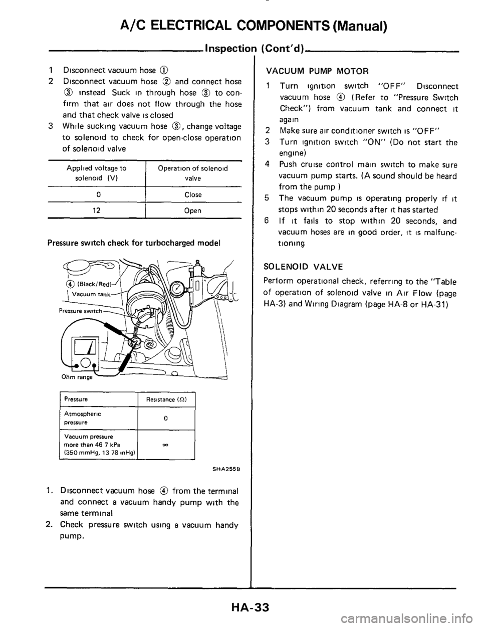
Applied voltage to
solenoid (V)
0
1 Disconnect vacuum hose @
2 Disconnect vacuum hose 3 and connect hose
@ instead Suck in through hose @ to con-
firm that
air does not flow through the hose
and that check
valve is closed
While sucking vacuum hose
0, change voltage
to solenoid to check for openclose operation
of solenoid valve
3 ~~
Operation of solenoid
valve
Close
12 1 Open ~ ~~ ~
Pressure
switch check for turbocharged model
I Pressure I Resistance In1 I
Atmospheric
presswe
Vacuum pressure
more than 46 7 kPa 1350 mmHg, 13 78 mHg1
SHAZ55E
1. Disconnect vacuum hose @ from the terminal
and connect
a vacuum handy pump with the
same terminal
2. Check pressure switch using a vacuum handy
pump.
VACUUM PUMP MOTOR
1 Turn ignition switch "OFF" Disconnect
vacuum hose
@ (Refer to "Pressure Switch
Check") from vacuum tank and connect
it
again
2 Make sure air conditioner switch is "OFF"
3 Turn ignition switch "ON" (Do not start the
engine)
4 Push cruise control main switch to make sure
vacuum pump starts. (A sound should
be heard
from the pump
)
5 The vacuum pump is operating properly if it
stops within 20 seconds after it has started
6 If it fails to stop within 20 seconds, and
vacuum hoses are in good order, it is malfunc-
tioning
SOLENOID VALVE
Perlorm operational check, referring to the "Table
of operation of solenoid valve in Air Flow (page
HA-3) and Wiring Diagram (page HA-8 or HA-31)
HA-33