Page 2 of 79
PRECAUTIONS
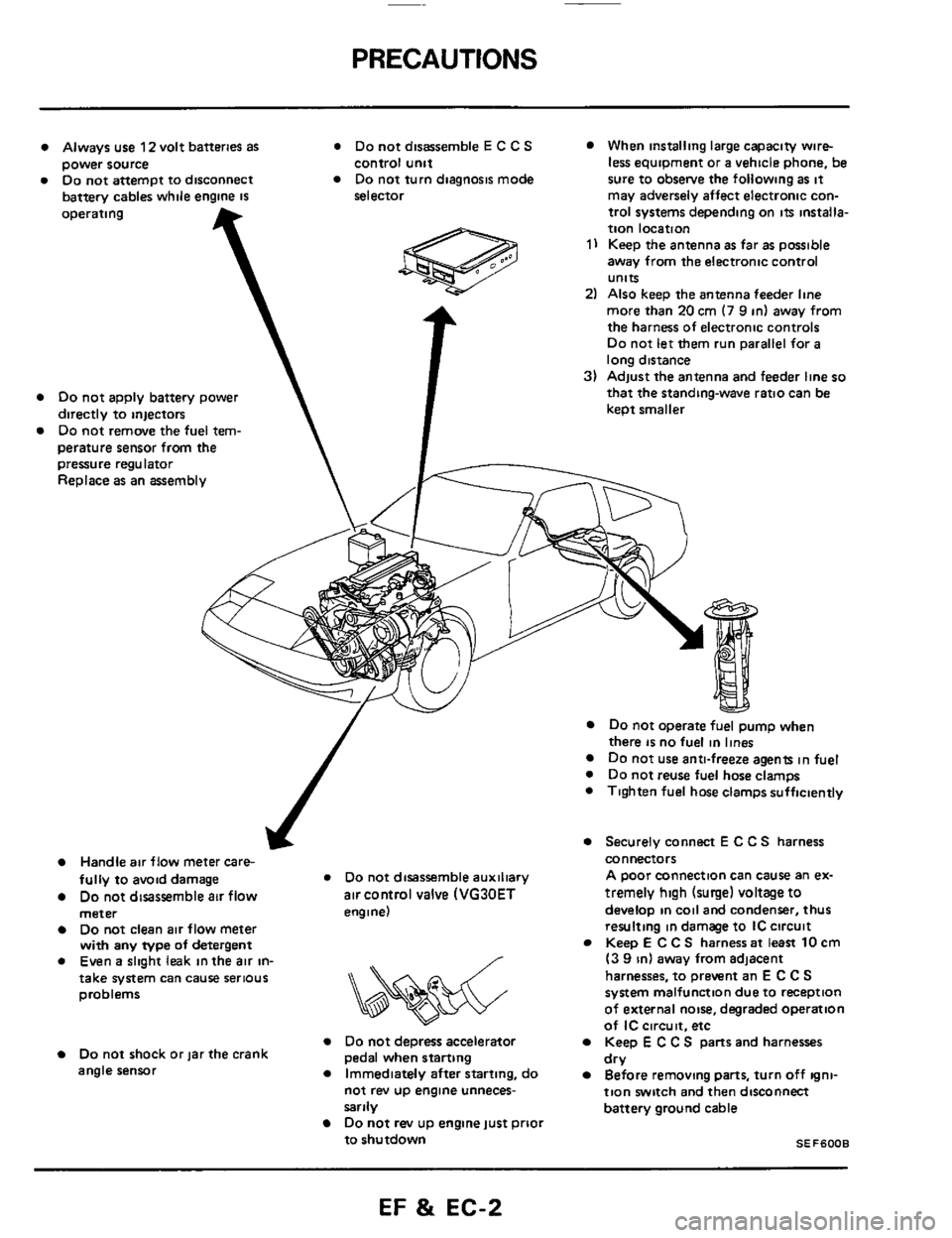
Always use 12 volt batteries as * Do not disassemble E C C S When installing large capacity wire-
Do not attempt to disconnect Do not turn diagnosis mode sure to obsetve the following as it power source
battery cables while engine
IS
control unit
selector less equipment or a vehicle phone, be
may adversely affect electronic con-
operating
Do not apply battery power
directly to injectors
Do not remove the fuel tem-
perature sensor from
the T
pressure regulator
Replace as an assembly
trol systems depending on its installa-
tion location
1) Keep the antenna as far as possible
away from the electronic control
units
2) Also keep the antenna feeder line
more than
20 cm (7 9 in) away from
the harness of electronic controls
Do not let them run parallel for a
long distance
3) Adjust the antenna and feeder line so
that the standing-wave ratio can be
keot smaller
J
Handle air flow meter care-
fully to avoid damage * Do not disassemble auxiliary
Do not disassemble air flow air control valve (VG30ET
meter engine)
Do not clean air flow meter
with any type of detergent
0 Even a slight leak in the air in- /
&&%$$?&
take system can cause serious
problems
Do not depress accelerator Do not shock or jar the crank
angle sensor
Immediately after starting, do
pedal when starting
not rev
up engine unneces-
sarily
Do not rev up engine just prioi
to shutdown
Do not operate fuel pump when
there is no fuel in lines Do not use anti-freeze agents in fuel
0 Do not reuse fuel hose clamps
0 Tighten fuel hose clamps sufficiently
Securely connect E C C S harness
connectors
A poor connection can cause an ex-
tremely
high (surge) voltage to
develop in coil and condenser, thus
resulting in damage to IC circuit
Keep
E C C S harness at least 10 cm
(3 9 in) away from adjacent
harnesses, to prevent an
E C C S
system malfunction due to reception
of external noise, degraded operation
of
IC circuit. etc
Keep E C C S parts and harnesses
Before removing parts, turn off igni-
tion switch and then disconnect
battery ground cable dry
SEF6008
EF & EC-2
Page 28 of 79
DIAGNOSTIC PROCEDURE
Caution
a. Before connecting or disconnecting E C C S
b
C
d
e
harness connector to or from any E C.C S.
unit, be sure to turn the ignition switch to the
"OFF" position and disconnect the negative
battery terminal
Otherwise, there may
be damage to control
unit
Do not attempt to disassemble any E C C S
component parts. To conduct electrical checks
on these component parts, closely follow the
steps outlined under "ELECTRONIC CON-
TROL SYSTEM INSPECTI0N"on pages EF
&
EC-43 through EF & EC-59.
When conducting self-diagnosing, follow the
steps outlined under "SELF-DIAGNOSIS" on
pages EF
& EC-35 through EF & EC-42 in
order to obtain accurate diagnosing results
After selfdiagnosing has been completed, erase
the memory properly
Always turn the diagnosis mode selector care-
fully using
a screwdriver If it is turned forci-
bly,
it may be damaged, resulting in the inabili-
ty to perform the self-diagnosing or to monitor
the mixture ratio
Before troubleshooting, ensure that
all harness
connectors are secure.
EF & EC-28
Page 43 of 79
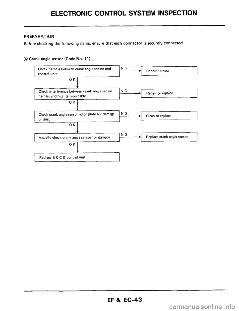
ELECTRONIC CONTROL SYSTEM INSPECTION
Check harness between crank angle sensor and
control unit
PREPARATION
Before checking the following items, ensure that each connector IS securely connected
N G ~ harness
Repair or replace harness and high tension cable
or dust
Visually check crank angle sensor for damage 1 “--+I Replace crank angle sensor
OK
Replace E C C S control unit 1
EF & EC-43
Page 65 of 79
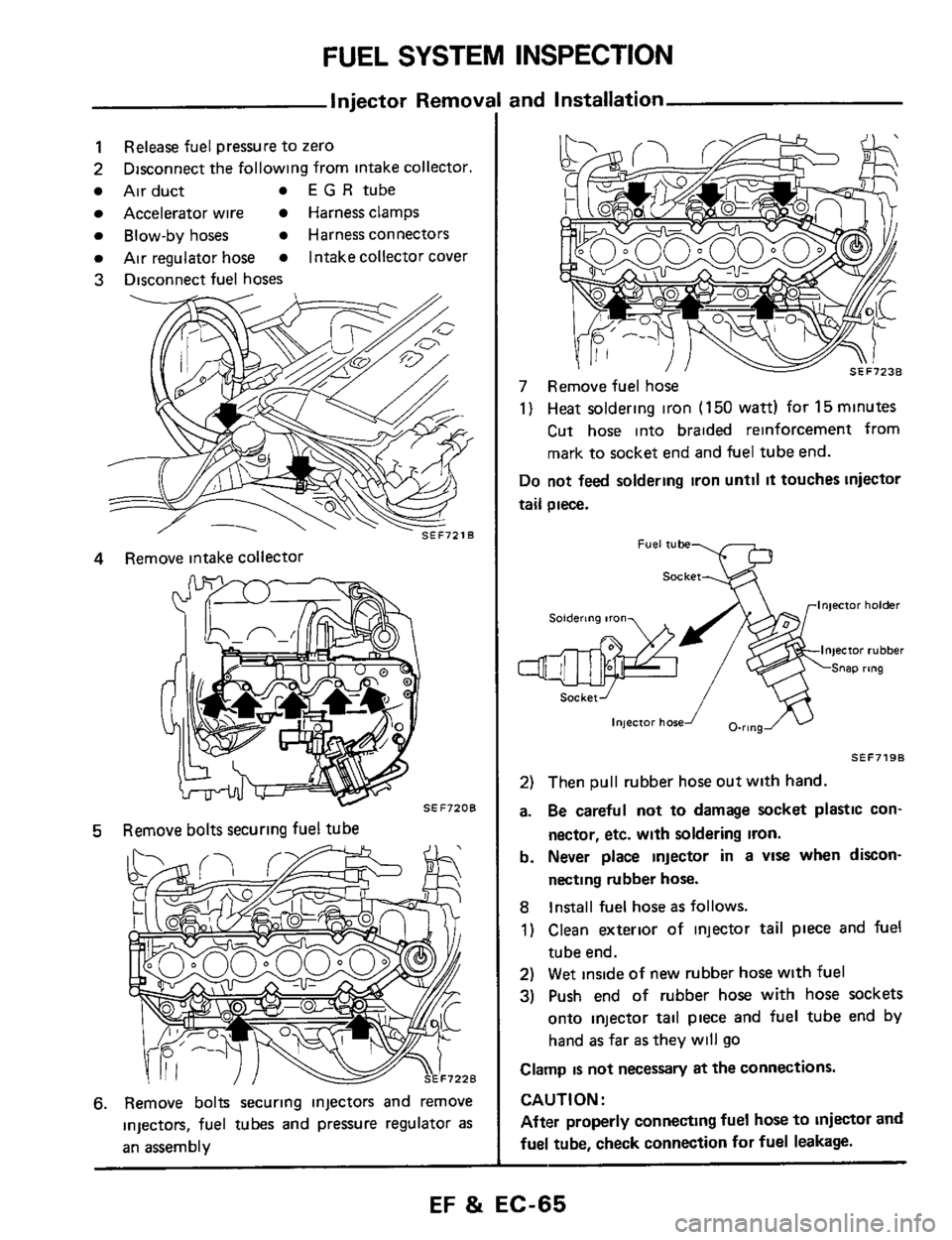
FUEL SYSTEM INSPECTION
Injector Removi
1
2
Air duct E G R tube
Accelerator wire Harness clamps
Blow-by hoses Harness connectors
Air regulator hose Intakecollector cover
3 Disconnect fuel hoses
Release fuel pressure to zero
Disconnect the following from intake collector.
4 Remove intake collector
5 Remove bolts securing fuel tube
6. Remove bolts securing injectors and remove
injecton, fuel tubes and pressure regulator
as
an assembly
and installation
7 Remove fuel hose
1) Heat soldering iron (150 watt) for 15minutes
Cut hose into braided reinforcement from
mark to socket end and
fuel tube end.
Do not feed soldermg iron until it touches injector
tail piece.
Socket
Fuel tube
Injector holder Soldering iron
InjeCtor rubber
Snap rtng
injector hosef O-ring
SEF719B
2) Then pull rubber hose out with hand.
a.
Be careful not to damage socket plastic con-
nector, etc. with soldering
iron.
b. Never place injector in a VIS when dixon-
necting rubber hose.
8
Install fuel hose as follows.
1) Clean exterior of injector
tail piece and fuel
tube end.
2) Wet inside of new rubber hose with fuel
3) Push end of rubber hose with hose sockets
onto injector tail piece and fuel tube end by
hand
as far as they will go
Clamp is not necessary at the connections.
CAUTION:
After properly connecting fuel hose
to injector and
fuel tube, check connection
for fuel leakage.
EF & EC-65
Page 68 of 79
TURBOCHARGER
Removal and Installation
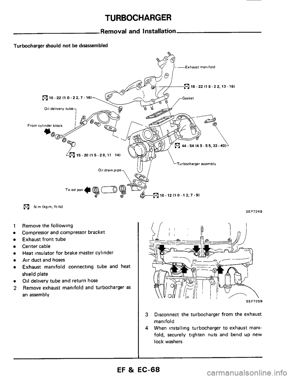
Turbocharger should not be disassembled
&- Exhaw manifold
(c1 18 -22 (1 8-22.13-161
10 -22 I1 0 -22.7.161
011 delivery tube
From cylinder block
*@
15-2OI15-20.11 14)
Turbocharger assembly
p? N m lkg-m. ft-lbl SEF724B
Remove the following
Compressor and compressor bracket
Exhaust front tube
Center cable
Heat insulator for brake master cylini
Air duct and hoses
Exhaust manifold connecting tube and heat
shield plate
Oil delivery tube and return hose
Remove exhaust manlfold and turbocharger
as
an assembly
SEF725B
3
4
Disconnect the turbocharger from the exhaust
manifold
When installing turbocharger
to exhaust mani-
fold, securely tighten nuts and bend
up new
lock washers
EF 8i EC-68
Page 79 of 79
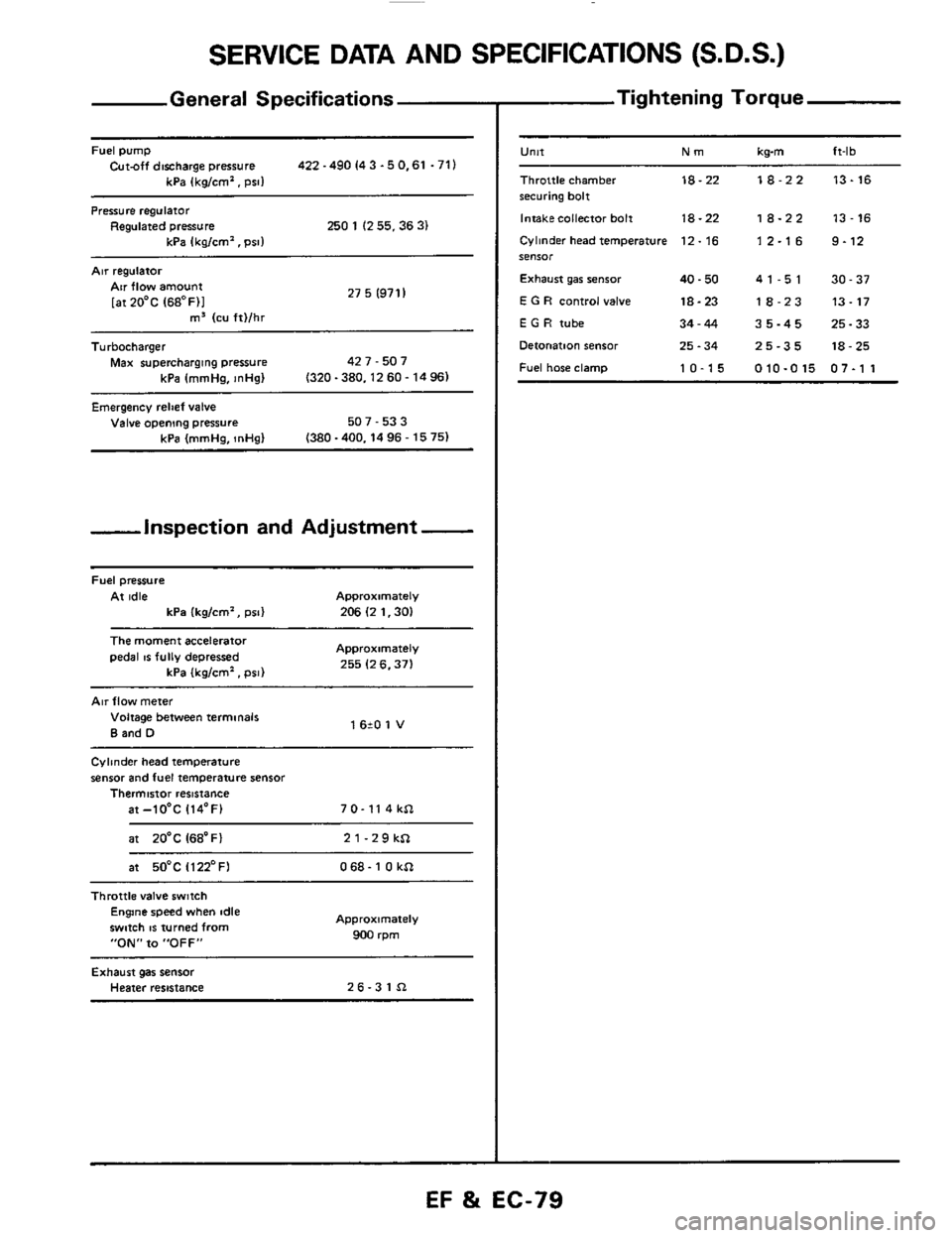
SERVICE DATA AND SPECIFICATIONS (S.D.S.)
General Specifications
Fuel pump Cut-off discharge pressure 422 -490 I4 3 -5 0.61 .71)
kPa (kg/cm'. psi1
Pressure regulator Regulated pressure 250 1 (2 55.36 3) kPa Ikalcm'. Dsll
Air regulatoi
27 5 (971 I Air flow amount
[atZO'C (68OF)I m3 (cu ft)/hr ~~
Turbocharger
Max supercharging pressure 42 7 - 507
kPa (mmHa.
InHal (320-380.1260-1496)
Emergency relief valve Valve opening pressure 507 - 53 3
(380 -400.14 96 - 15 75) kPa (mmHg, InHg)
-inspection and Adjustment -
Fuel pressure
At idle Approximately
kPa (kg/cm', psi) 206 (2 1.30)
The moment accelerator
pedal IS fully depressed Approximately
255 (2 6.371 kPa (kglcm'. psi)
Air flow meter
Voltage between terminals
B and D 1 620 1 V
Cylinder head temperature
sensor and fuel temperature sensor Thermistor resistance
at-lO'C 114'F) 7 0- 11 4 kSl
at 20'C I68'Fl 21-29kSl
at 50°C Il22'FI 068- 1 0 kSl ~~~~
Throttle
valve switch Engine speed when idle
swmh
IS turned from
"ON" to "OFF"
Approximately
900 rpm
Exhaust gas sensor Heater resistance 26-31Sl
- Tightening Torque
-
U"lt Nm kwn ft-lb
Throttle chamber 18-22 18-22 13-16 securing bolt
Intakecollector bolt
18-22 18-22 13-16
Cylinder head temperature 12. 16 1 2.1 6 9.12 SeIlSOr
Exhaust gar senior 40.50 41-51 30-37
E G R control valve 18-23 18-23 13-17
E G H tube 34-44 35-45 25-33
Detonation sensor 25.34 25-35 18-25
Fuel hose clamp 10-15 010-015 07-1 1
EF %i EC-79