Page 12 of 116
STARTING SYSTEM -Starter-
Brush Check
BRUSH
Check wear of brush
Wear limit length: 11 mm (0.43 in)
Vernier caliper
SEL626B
Excessive wear Replace
BRUSH HOLDER
1 Perform insulation test between brush holder
(positive side) and its base (negative side)
SE L568B
Continuity exists . Replace
smoothly
2 Check brush holder to see if it moves
If brush holder is bent, replace it, if sliding
surface
is dirty, clean
Field Coil Check
Continuity test (between field coil positive
terminal and positive brushes)
ositive terminal
‘Ohmmeter
No continuity Replace fielk ~
SELUq6A
:oil
Insulation test (between field coil positive
terminal
and yoke)
Postwe terminal
I
1%
Continuity exists Replace field coil
EL-I 2
Page 21 of 116
CHARGING SYSTEM -Alternator-
Reasi
Carefully observe the following instructions
1 When soldering each stator coil lead wire to
diode assembly terminal, carry out the opera-
tion
as fast as possible
2 When soldering brush lead wire, observe the
following
Position brush so that its wear limit line
protrudes 2 mm (0 08 in) beyond end face
of brush holder
Solder points
SEL6320
3 Fit ring into groove in rear bearing so that it is
as close to the adjacent area as possible.
Quantity of prorrusion FIX ring at the position of minimum protrusion
mbly
4 Before installing front cover with pulley and
rotor with
rear cover, push brush up with
fingers and retain brush, by inserting brush
lift
into brush lift hole from outside
After installing, remove wire for brush
lift
EE540
EE541
5 After installing front and rear sides of alter-
nator, pull brush lift by pushing toward center
Do not pull brush lift by pushing toward outside
of cover as it will damage slip ring sliding surface.
EL-21
Page 33 of 116

HEADLAMP
0
0
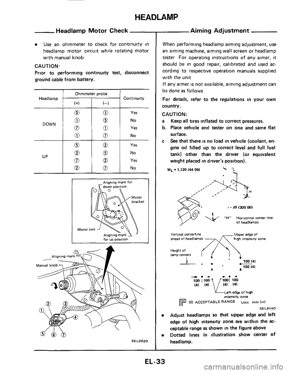
Headlamp Motor Check
0 No
8 Yes
Use an ohmmeter to check for continuity in
headlamp motor circuit while rotating motor
with manual knob
CAUTION.
Prior to performing continuity test, disconnect
ground cable from battery.
Ohmmeter probe
Headlamp Continuity
Yes
No
Alqning mark for
for up posltlon
SEL652D
- Aiming Adjustment
When performing headlamp aiming adjustment, use
ail aiming machine, aiming wall screen or headlamp
tester For operating instructions of any airner, it
should be in good repair, calibrated and used ac-
cording to respective operation manuals supplied
with the unit
If any aimer is not available, aiming adjustment can
be done
as follows
For details, refer to the regulations in your own
country.
CAUTION:
a Keep all tires inflated to correct pressures.
b. Place vehicle and tester on
one and same flat
surface.
c See that there is no load in vehicle (coolant, en-
gine oil filled up to correct level and full fuel
tank) other than
the driver (or equivalent
weight placed in driver's position).
W~=l,ltO(4409I c 'L
-7
, - LO 1300 001
Of headlamps
UPper edge of Vertical centerline ahead of headlamps -x high tntenrw zone
Height of lamp centers I .- 100 141
100 (41 .-
L A
4.. I.. 100 1100 1001 loo (41 (41 / (41 (41
KLeft edge of high intensity zone
= ACCEPTABLE RANGE untt mm (in1
SEL914D
Adjust headlamps so that upper edge and left
edge
of high intensty zone are within the ac-
ceptable range as shown
in the figure above
Dotted lines in illustration show center of
headlamp.
EL-33
Page 48 of 116
METER AND GAUGES - Digital Type Combination Meter
Trouble-shooting (Cont'd)
Replace meter
and gauge assembly
Speedometer does not operate
Go to "Display Check"
Check harness between
speed sensor and meter
OK
Go to "Power
Unit Check"
T T Replace meter Replace
and gauge assembly power Unit
Go to "Speed Sensor Signal Check" to check speed
sensor output
Go to "Display Check"
Go to "Power
Unit Check"
OK
Replace meter Replace
and gauge assembly power unit
.
1 Check ignition coil circuit I
and gauge assen
1'
T lNG Replace meter Check resistor, ignition
and
gauge assembly coil and power transistor
(Refer to ignition system)
1 Disconnect meter harness connector
2
3 Check terminal voltage between @ and
(white)
Turn ignition switch to
"ON".
0
VOltmeter SEL6660
EL-48
Page 52 of 116
METER AND GAUGES - Digital Type Combination Meter
Trouble-shooting (Cont’d)
Go to “Displav Check”
ING OK
Replace meter and
gauge assembly
v
Check oil pressure sensor circuit
OK NG
Go to “Oil Pressure
Sensor Check” Replace meter
and gauge
assembly
Check harness between Replace oil
oil pressure sensor and meter pressure
sensor
1 Disconnect meter harness connector
(black)
2 Measure resistance between @ and @
when engine stopping and running
Ohmmeter
Engine Resistance
Approx 75R or more
Idling Approx 60R or less
SEL672D
“Trip”, ”Ave speed” and “Dist to empty” meters
1 Go to ”Display Check” 1
Go to “Power Unit Check”
Replace trip Replace power unit
meter assembly
Only “Ave speed” meter does not operate
I
I Go to “Display Check“ I
lNG
OK
Replace trip
meter assembly
I Check clock for proper operation I
Check harness between Replace clock
clock and meter
I OK v
Replace trip meter assembly
Page 53 of 116

METER AND GAUGES - Digital Type Combination Meter
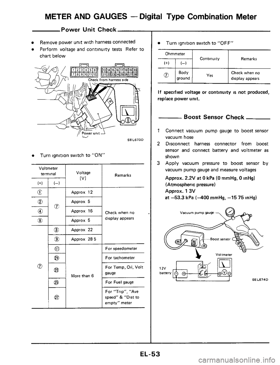
Power Unit Check
Voltmeter
terminal
(f) (-)
E -
-%; 0
0
@I
__
@
9
0
0
Remove power unit with harness connected
Perform voltage and continuity tests Refer to
chart below
I Voltage
[VI
Approx 12
Approx 5
Approx 16
Approx 5
Approx 22
Approx 285
Turn ignition switch to "ON"
1 - 1 More than 6
Remarks
Check when no
display appears
For speedometer
For tachometer
For Temp,
Oil, Volt
sause
For Fuel gauge
For "Trip", "Ave
speed"
& "Dirt to
empty" meter
Turn ignition switch to "OFF"
Ohmmeter
Continuity Remarks
Check when no
ground display appears
If specified voltage or continuity is not produced,
replace power unit.
- Boost Sensor Check
1 Connect vacuum pump gauge to boost sensor
vacuum hose
2 Disconnect harness connector from boost
sensor and connect battery and voltmeter
as
shown
3 Apply vacuum pressure to boost sensor by
vacuum pump gauge and measure voltages
Approx.
2.2V at 0 kPa (0 mmHg, 0 inHg)
(Atmospheric pressure)
Approx.
1 3V
at -53.3 kPa (-400 mmHg, -15 75 inHg)
vacuum pump gauge
SEL674D
EL-53
Page 56 of 116
METER AND GAUGES - Digital Type Combination Meter
Fuel Tank Gauge Check
For removal, refer to FE section
Ohmmeter terminal Float
Main gauge
Resistance value
Approx 10 - 20Q
Approx 480 - 520Q
Approx 100 - 1 1 OQ
Approx 4Q or below
Approx
870.930Q
Sub gauge
SEL675D
SEL676D
-Water Temp Sensor Check -
Cylinder head R H side
SEL677D
-Oil Pressure Sensor Check -
-
011 filter 7 \
SEL678D
Ohmmeter
terminal With engine With engine
stopped 1 running (idling)
ca On
+I;'''' I More than 74Q I Less than 60.Q
EL-56
Page 65 of 116
METER AND GAUGES -Needle Type Combination Meter
Combination Meter
pj
0, SENSO
35 36 31
1 TACHO-
METER
BBpgBW *Em 8EAR
FUEL BELT DOOR BRAKE CHARGE OIL RADIATO HEAD- STOP&
COOLANl LAMP TAIL LAMP
0 32 -- a: "E NATION 30
ILLUMI-
0 33 -U 18 19 20 s;14 15 5 23
24 2. 29 1 3 4 11
SEL690D
EL-65