Page 1 of 116

ELECTRICAL SYSTEM
I
SECTION EL
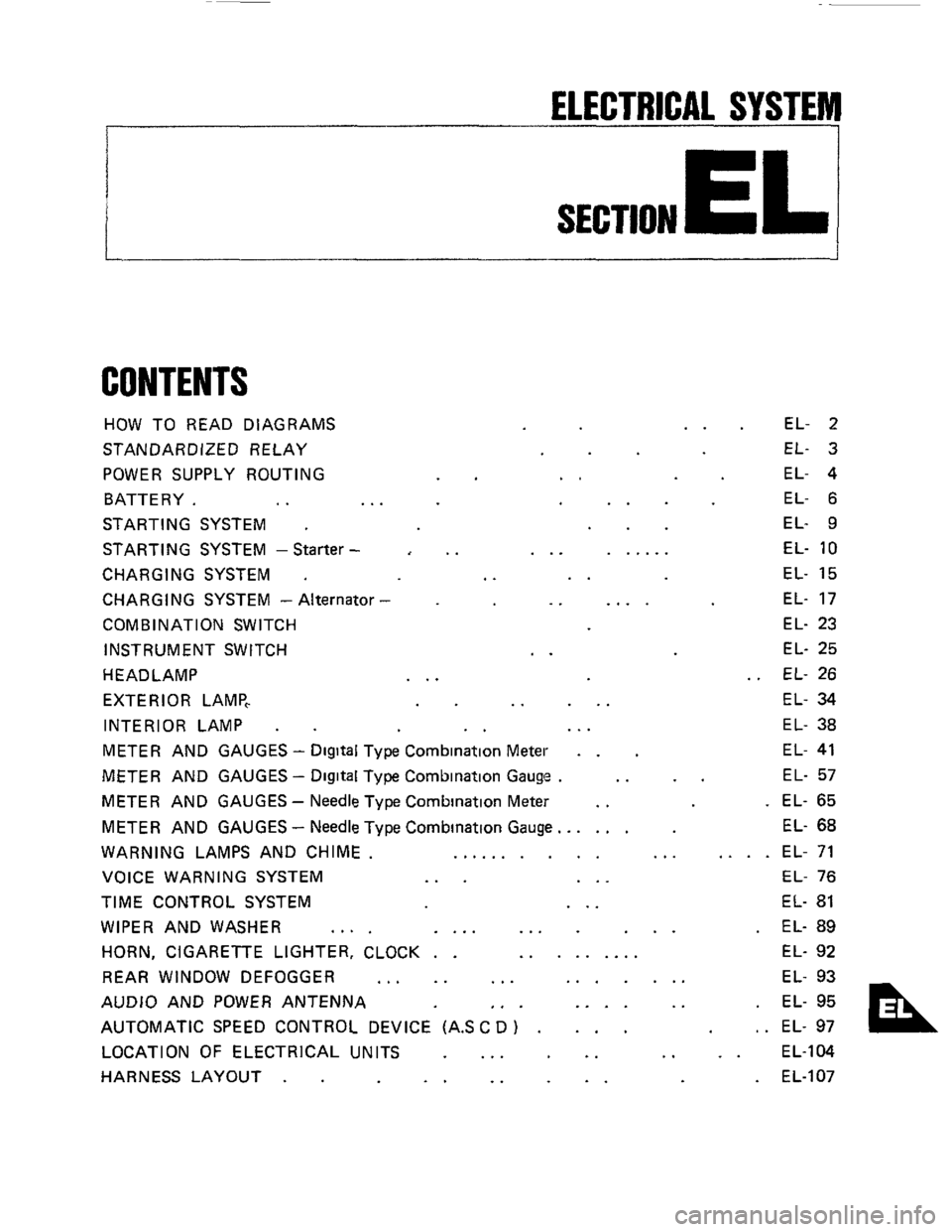
CONTENTS
HOW TO READ DIAGRAMS
STANDARDIZED RELAY
POWER SUPPLY ROUTING
BATTERY.
.. ..
STARTING SYSTEM .
STARTING SYSTEM -Starter -
CHARGING SYSTEM .
CHARGING SYSTEM - Alternator
COMB IN AT1 ON SWITCH
INSTRUMENT SWITCH
HEADLAMP
EXTERIOR LAMP,
INTERIOR LAMP
.
..
..
..
..
..
... ......
..
.. ....
..
.. ...
EL- 2
EL- 3
EL- 4
EL- 6
EL- 9
EL-
10
EL- 15
EL- 17
EL- 23
EL- 25
EL- 26
EL- 34
EL- 38
METER AND GAUGES - Digital Type Combination Meter . . EL- 41
METER AND GAUGES - Digital Type Combination Gauge . .. .. EL- 57
METER AND GAUGES - Needle Type Combination Meter .. . EL- 65
METER AND GAUGES
- Needle Type Combination Gauge.. .... EL- 68
WARNING LAMPS AND CHIME. .......... ... .... EL- 71
VOICE WARNING SYSTEM
... ... EL- 76
TIME CONTROL SYSTEM ... EL- 81
WIPER AND WASHER .... .... ... ... . EL- 89
HORN, CIGARETTE LIGHTER, CLOCK . . ......... EL- 92
REAR WINDOW DEFOGGER
... .. ... ....... EL- 93
AUDIO AND POWER ANTENNA
,. . .... .. . EL- 95
AUTOMATIC SPEED CONTROL DEVICE (AS
C D ) . ... , . EL- 97
LOCATION OF ELECTRICAL UNITS
... .. .. .. EL-104
HARNESS LAYOUT
. . .. .. .. . EL-107
Page 2 of 116

HOW TO READ DIAGRAMS
I
POWER SUPPLY ROUTING
This diagram is helpful in identifying specific prob-
lems
in the power supply portion of the electrical
circuits. For example, let's say
a vehicle has an in-
operative
rear window defogger A quick check
proves that meter and
gauges in the vehicle are
operative The power supply diagram shows that
there cannot be
a problem between the battery,
ignition relay, ignition switch or fuse since the
power supply circuit for the
rear window defogger
Example
BRANCH M/T model
AlT model
n
@ M/Tmodel
@ AITmodel
t
ABBREVIATIONS
is common with the meter and gauges. Therefore,
the cause of this specific problem must
lie past the
fuse, such
as in the wiring, rear window defogger,
or ground.
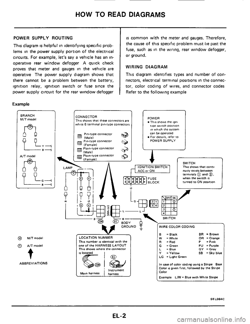
WIRING DIAGRAM
This diagram identifies types and number of con-
nectors, electrical
terminal positions in the connec-
tor, color coding of wires, and connector codes
Refer to the following example
CONNECTOR This shows that there connectors are white 6 terminal pin-type connectors
Pin-type connector (Male)
(Female)
(Male)
(Female)
833 Piaan-type connector
gg Piatn-type connector
POWER This shows the tgni tion witch ~osition ~n which the system can be operated For deiailr, refer 10 POWER SUPPLY
A r
I
1 v SWITCH ., , ,-,. -..,m I This shows that conti-
u
f
L-
WIRE COLOR CODING
This number IS !dentical with the one of the HARNESS LAYOUT This show where the mnnenor
CarON I nutty exists between termmels @ and 0, when the switch 16 turned 10 ON rmition
B W R
BR =Brown = Black OR =Orange =White =Red P =Pink G =Green PU =Purple L =Blue GY =Gray Y =Yellow SB =Sky blue LG = Laghi Green
In case of color coding using a Stripe Bare Color IS given fmt. followed by the Stripe Color
Example LIW = Blue with White Stripe
EL-2
Page 4 of 116
~ POWER SUPPLY ROUTING
Wiring
Diagram
FUSIBLE LINK BOX 8ATTERY BR
-
STARTING
Charging system
rc- I
-Power wmdow
EL-4
Page 5 of 116
POWER SUPPLY ROUTING
Fuse Fusible Link
_I
Check
SEL276
a
b
c d
If fuse is blown, be sure to eliminate cause of
problem before installing new fuse
Use fuse of specified rating. Never use fuse of
more than specified rating
Do not install fuse in oblique direction, always
insert
it into fuse holder properly
Remove fuse for clock if vehicle
is not used for
a long period of time.
A melted fusible link can be detected either by
visual inspection or by feeling with finger tip If its
condition is questionable, use circuit tester or test
lamp
CAUTION
a If fusible link should melt, it is possible that
critical circuit (power supply or large current
carrying circuit)
is shorted In such a case, care-
fully check and eliminate cause
of problem
Never wrap periphery
of fusible link with vinyl
tape Extreme care should
be taken with this
link to ensure
that it does not come into con-
tact with any other wiring harness or vinyl or
rubber parts
b
EL-5
Page 42 of 116
METER AND GAUGES - Digital Type Combination Meter
Combination Meter (Cont'd)
--
Power ""lt
To power unit
12 13 14 15 24 30 16 17 18 19 20 21 22 6 21 28
40
45 55 46 47 48 49 50 51 53 54
;I4 E
i
SE L661 D
EL-42
Page 45 of 116
METER AND GAUGES - Digital Type Combination Meter
Wiring Diagram (Cont'd)
GY LIR
tiT POWER
TACH0 & TORDUE METER
SPEED METER
SEL663D
EL-45
Page 47 of 116

METER AND GAUGES - Digital Type Combination Meter
-
(+) (-) OFF
Display Check (Cont'd)
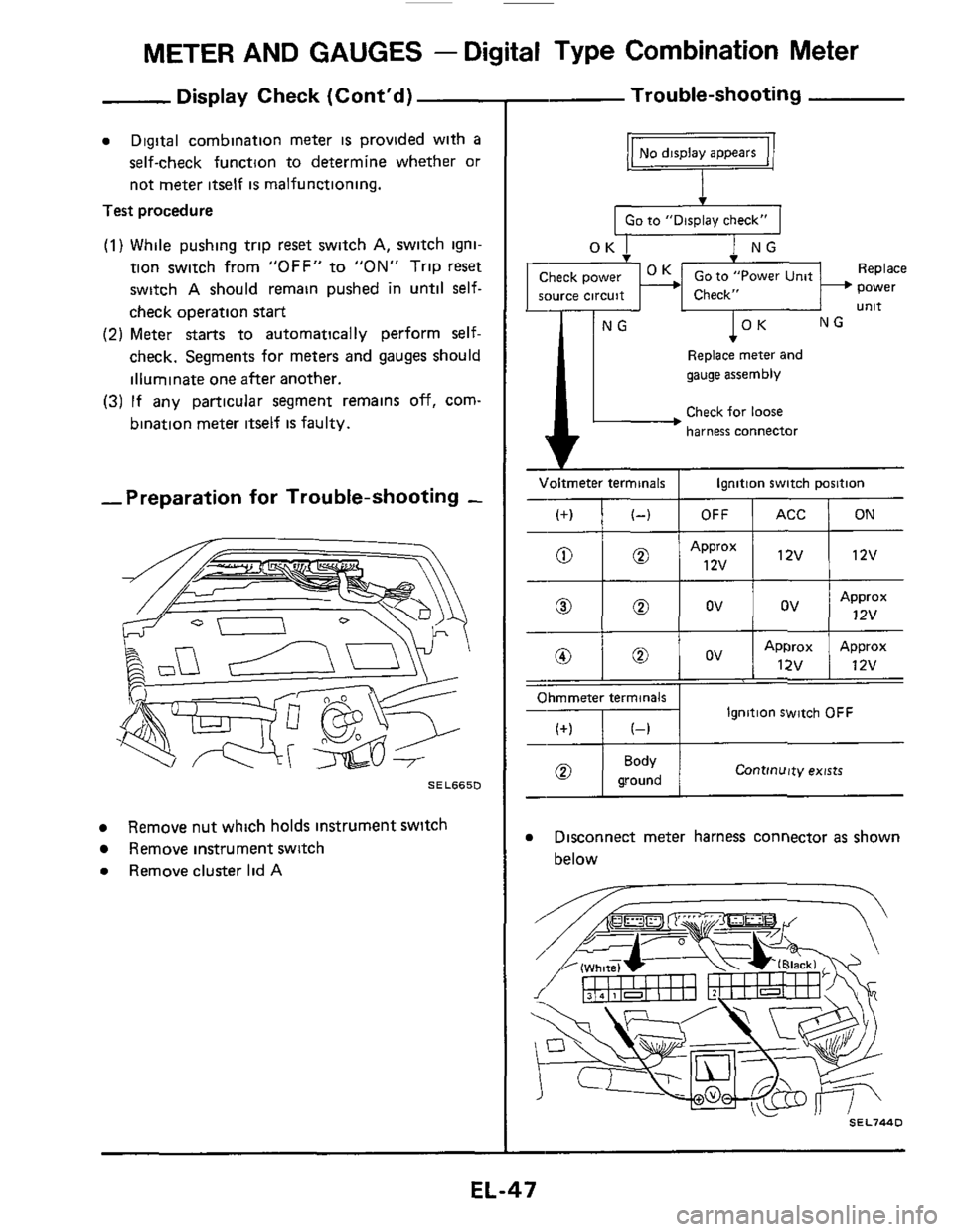
a Digital combination meter is provided with a
self-check function to determine whether or
not meter itself
is malfunctioning.
Test procedure
(1) While pushing trip reset switch A, switch igni-
tion switch from
"OFF" to "ON" Trip reset
switch
A should remain pushed in until self-
check operation start
(2) Meter starts to automatically perform self-
check. Segments for meters and gauges should
illuminate one after another.
(3) If any particular segment remains off, corn-
bination meter
itself is faulty.
ACC ON -Preparation for Trouble-shooting -
0
Approx
12v 0 ov ov
SEL665D
a
Remove instrument switch
a Remove cluster lid A
Remove nut which holds instrument switch
- Trouble-shooting
I Go to "Display check" I
1 NG
power source circuit unit
-IF' L-IF-NG
Replace meter and
gauge assembly
Check for loose
harness connector
Voltmeter terminals Ignition switch position
Ohmmeter terminals
Ignition Switch OFF
Continuity exists ground
a Disconnect meter harness connector as shown
below
.
SEL744D
-
EL-47
Page 48 of 116
METER AND GAUGES - Digital Type Combination Meter
Trouble-shooting (Cont'd)
Replace meter
and gauge assembly
Speedometer does not operate
Go to "Display Check"
Check harness between
speed sensor and meter
OK
Go to "Power
Unit Check"
T T Replace meter Replace
and gauge assembly power Unit
Go to "Speed Sensor Signal Check" to check speed
sensor output
Go to "Display Check"
Go to "Power
Unit Check"
OK
Replace meter Replace
and gauge assembly power unit
.
1 Check ignition coil circuit I
and gauge assen
1'
T lNG Replace meter Check resistor, ignition
and
gauge assembly coil and power transistor
(Refer to ignition system)
1 Disconnect meter harness connector
2
3 Check terminal voltage between @ and
(white)
Turn ignition switch to
"ON".
0
VOltmeter SEL6660
EL-48