Page 1 of 21
BRAKE SYSTEM
P 7- I
SECTION BR
CONTENTS
BRAKE HYDRAULIC LINE ..
BRAKE PEDAL. . . ..
MASTER CYLINDER .
BRAKE BOOSTER
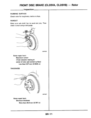
FRONT DISC BRAKE (CL28VA, CL28VB) - Rotor
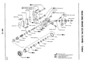
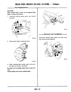
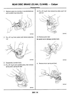
REAR DISC BRAKE (CL14H, CL14HB) - Callper
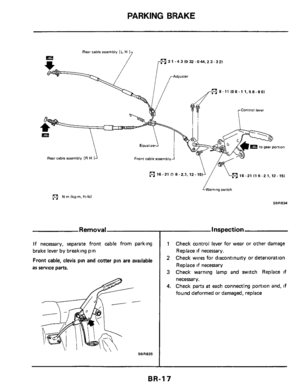
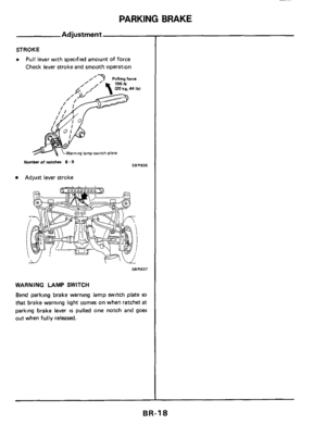
PARKING BRAKE
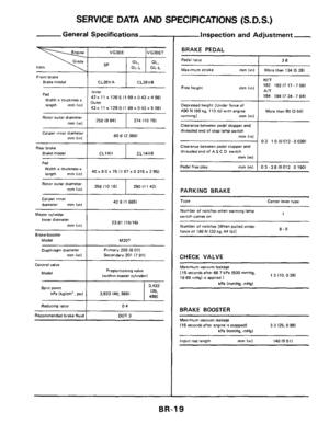
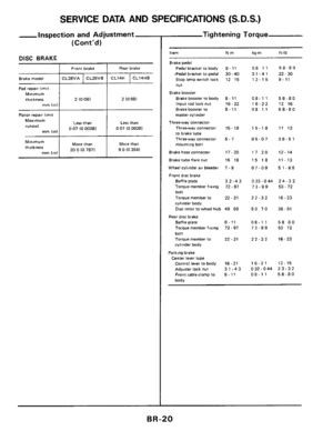
SERVICE DATA AND SPECIFICATIONS
6 D.S)
SPECIAL SERVICE TOOL
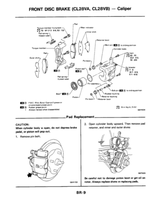
FRONT DISC BRAKE (CL28VA, CL28VB) - Caliper
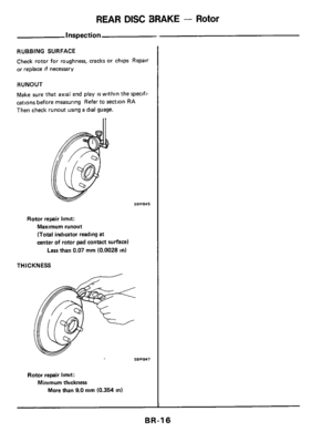
REAR DISC BRAKE - Rotor ..
.. .. .. BR- 2
. BR- 4
BR- 6
BR- 7
BR- 9
. . . BR-11
.. BR-12
BR-16
. .. . BR-17
. BR-19
.. . .. BR-21
Page 2 of 21
BRAKE HYDRAULIC LINE
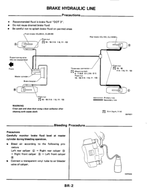
rn Recommended fluid is brake fluid "DOT 3".
Do not reuse drained brake fluid
Be careful not to splash brake fluid on painted areas
Front brake lCL28VA. CL28VB)
rFlare nut
7
7
Rear brake lCL14H. CL14HB)
7 0 15- 18 I1 5- 18.11.131
@@.A
Three-way connector I1 5. 1 8, 11 - 131
Flare nut 15-18 I1 5- 18.11 -13)
\Flare nut
0 15.18 I1 5.18.11.13)
WARNING
Clean pad and shoe dust using a dust
collector after
cleaning with waste cloth
Primary llne - Secondary lone
N m lkg-m,ft Ibl
SBR821
Bleeding Procedure
Precautions
Carefully monitor brake fluid level at master
cylinder during bleeding operation.
Bleed air according to the following pro-
cedure
Left rear caliper @ -t Right rear caliper @
-t Right front caliper @ -f Left front caliper
Connect a transparent vinyl tube to air bleeder
valve of caliper.
U SBRSOS
BR-2
Page 3 of 21
BRAKE HYDRAULIC LINE
Removal and Installation
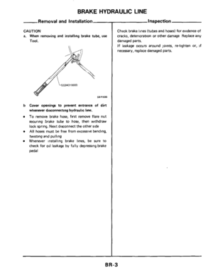
CAUTION
a. When removing and installing brake tube, use
Tool.
b Cover openings to prevent entrance of dirt
whenever disconnecting hydraulic line.
To remove brake hose, first remove flare nut
securing brake
tube to hose, then withdraw
lock spring. Next disconnect the other side
All hoses must be free from excessive bending,
twisting and pulling
Whenever installing brake lines, be sure to
check for
oil leakage by fully depressing brake
pedal
- Inspection
Check brake lines (tubes and hoses) for evidence of
cracks, deterioration or other damage Replace any
damaged
parts.
If leakage occurs around joints, retighten or, if
necessary, replace damaged parts.
BR-3
Page 4 of 21
BRAKE PEDAL
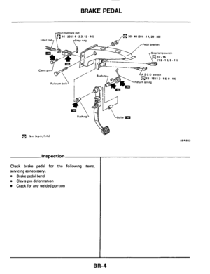
Input rod lock nut
30-40 I3 1.4 1,ZZ- 30)
Pedal bracket
Stop lamp switch
I1 2. 15,9- 111
N rn lkg-m, ft-lb)
Inspection
Check brake pedal for the following items,
servicing
as necessary.
Brake pedal bend
Clevis pin deformation
Crack for any welded portion
SBR822
BR-4
Page 5 of 21

BRAKEPEDAL
Adjustment
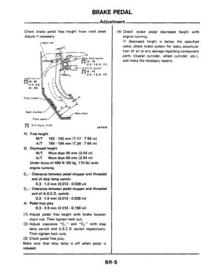
Check brake pedal free height from melt sheet
Adjust
if necessary
I1 2.15.9- 111
AS C D switch
I /-k I1 2 - 1 5,9.111
Dash insulator
N m 1kg-m. ft-lbl
sheet
SERE38
H: Free height
M/T
A/T
D: Depressed height
M/T
A/T
I82 - 192 mm (7.17 - 7 56 in)
184 - 194 mm (7.24 - 7 64 in)
More than
90 mm (3.54 in)
More than 90 mm (3.54 in)
Under force of 490 N (50 kg. 110 Ib) with
engine running.
C, : Clearance between pedal stopper and threaded
end
of stop lamp switch.
Cz : Clearance between pedal stopper and threaded
end of A.S.C.D. switch.
0.3 - 1.0 mm (0.012 ~ 0.039 in)
0.3 - 1.0 mm (0.012 - 0.039 in)
0.3 - 3 8 mm (0 012 - 0.150 in)
A: Pedal free play
(1) Adjust pedal free height with brake booster
input rod. Then tighten lock nut.
(2) Adjust clearance "C1" and "C2" with stop
lamp switch and A.S.C
D switch respectively.
Then tighten lock nuts.
(3) Check pedal free play.
Make sure that
stop lamp is off when pedal is
released.
(4) Check brake pedal depressed height with
engine running.
If depressed height
is below the specified
value, check brake system for leaks, accumula-
tion of
air or any damage regarding component
parts (master cylinder, wheel cylinder, etc.),
and make the necessary repairs.
BR-5
Page 6 of 21
Page 7 of 21
BRAKE BOOSTER
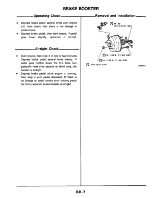
Operating Check
Depress brake pedal several times with engine
off, then check that there
is not change in
pedal stroke
Depress brake pedal, then
start engine. If pedal
goes down slightly, operation
is normal
Airtight Check
Start engine, then stop it in one or two minutes.
Depress brake pedal several times slowly. If
pedal goes further down the
first time, but
gradually
rises after second or third time, the
booster
is airtight.
Depress brake pedal while engine
is running,
then stop
it with pedal depressed. If there is
no change in pedal stroke after holding pedal
for thirty seconds, brake booster
is airtight
--Removal and Installation
(9116-22 (1 6 -2 2.12.16
(91 8. 11 (0 8. 1.1,5.8.8.01 1
8 - 11 (0 8 - 1 1,5.8.8.01
SBR831 (c1 N rn (kg-m, ft-lbl
BR-7
Page 8 of 21
BRAKE BOOSTER
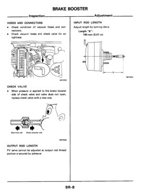
Inspection
HOSES AND CONNECTORS
0 Check condition of vacuum hoses and con-
0 Check vacuum hoses and check valve for air
nections.
tightness
68R832
CHECK VALVE
0 When pressure is applied to the brake booster
side of check valve and valve does not open,
replace check valve with
a new one.
Manlfold %de Brake booster ride
S8R846
OUTPUT ROD LENGTH
PV servo cannot be adjusted as output rod thread
portion
is secured by adhesive
Adjustment
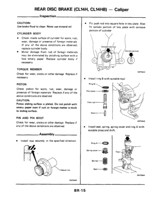
INPUT ROD LENGTH
Adjust length by turning Clevis.
Length "B":
140 mm (5.51 in1
BR-8
 - Rotor
REAR DISC BRAKE (CL14H, CL1")

rFlare nu")


Pedal bracket
Stop lamp switch
I1 2. 15,9- 111
N rn lkg-m, ft-lb)
Inspection
Check brake pedal for the following items,
servicing
as")


