Page 6 of 99
GENERAL SERVICE NOTICE
Oil Channel
Oil channels which connect components are
located in the
areas shown below.
OIL CHANNELS IN OIL PUMP
Oil pump cover ride
11 pump suction hole Cooler in pressure
011 pump discharge hold LTorque converter in pressure
Oil pump housing ride
ne oressure
SAT499
SAT500
OIL CHANNELS IN TRANSMISSION CASE
Front face rlde
Front & 0 D lubrication Forward clutch (Rear1
gh-reverse clutch
011 pump discharge hole
Direct clutch apply &OD sew0 release pressure
0 0 indicator pressure
SAT501
Lower face side
Governor pressure (To control valve)
Governor feed
(From control
valve)
LOW & reverse brake
High-reverse clutch IFrontl pressure SAT502
ii
OIL CHANNELS IN O.D. CASE
011 pump suction hole Hlgh-reverse clutch (Front1 pressure
Forward clutch
(Rear) Oresure
ront & 0 D lubrication
SAT645 In regards to oneway plug. refer to page AT-32.
AT-6
Page 7 of 99
GENERAL SERVICE NOTICE
I (Cont'd) Oil Cham
OIL CHANNELS IN DRUM SUPPORT OIL CHANNELS IN CONVERTER HOUSING
To lock-up ~ontrol valve
rDrain (E4N71Bl
clutch (Front)
Forward clutch
clutch pressure Front & 0 0 lubrmtmn
SAT706
3peration Mechanic:
In the E4N71B and 4N71B automatic transmission, each part operates as shown in the following table at
each gear select position
'arking
pawl
Htgh-
'everse
Front) Forward clutch (Rear) 0 D band servo Direct
clutch Range -
Release
ON ON
1 Reverse 1 ON 1 ION) ON
+-
ON I
I Neutral I ON I (ON) ON
T-
ON
-
ON
-
ON
ON
JT
I ION
'34
(0 D 1 ON I ON
Second I ON I (ON) ON
1 ON I (ON) 12
(Second) ON ON I ON
ON ord ON I I ON
The low & reverse brake IS applied In "1 I" range to prevent free wheeling when coasting and allows engine braking.
AT-7
Page 10 of 99
ON-VEHICLE SERVICE
Contrl
1. Drain fluid by removing oil pan.
2. Remove kickdown solenoid and vacuum dia
phragm
23 rod
Be careful not to lose vacuum rod.
Vacuum diaphragm
SAT506
3. Remove control valve assembly.
Be careful not to drop manual valve out of valve
body.
4. Disassemble, inspect and assemble control valve
assembly Refer to Control Valve Body.
5. Install control valve assembly.
0 Set manual shaft at Neutral, then align manual
plate with groove in manual valve of control
valve assembly.
Securing bolts come
in 3 different lengths. 0
1 40 mm I1 51 in) 2 35 mm (1 38 in1 3 25mm1098mI
After installing control valve to transmission
case, make sure that control lever can be
moved to all positions.
6 Install kickdown solenoid and vacuum dia-
phragm
& rod.
Make sure that vacuum diaphragm rod does not
interfere with side plate
of control valve.
AT-I 0
Page 11 of 99
ON-VEHICLE SERVICE
-Extension Oil Seal Replacement-
1. Remove oil seal
. -. .
2 Apply coat of A.T.F. to oil seal surface, then
drive new seal into place.
3 Coat sealing lips with vaseline, then install
propeller shaft
Parking Component
1 Remove oil pan.
2 Remove propeller shaft.
3. Remove speedometer pinion.
SAT51 1
4 Support transmlssion with a jack, then remove
rear mounting bolts.
AT-1 1
Page 12 of 99

~ ~~ ON-VEHICLE
SERVICE
-Parking Component (Cont'd)-
5. Remove rear extension bolts, then draw out
rear extension with rear mounting.
6. Remove control valve assembly.
7. Inspect and repair parking components Check
component
parts for wear or damage.
-Governor Valve Assembly
1 Drain oil by removing oil pan.
2. Remove rear extension with rear mounting
3. Remove governor valve assembly.
4. Inspect and repair governor valve assembly.
Refer to Governor for inspection
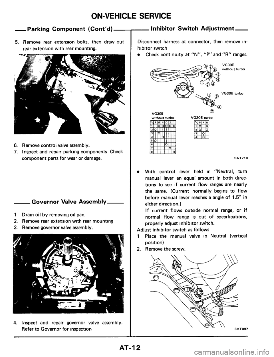
-Inhibitor Switch Adjustment-
Disconnect harness at connector, then remove in-
hibitor switch
Check continuity at "N", "F'" and "R" ranges.
VG30E without turbo
VG30E turbo
VG30E wnhout turbo
0
VG30E turbo
SAT710
With control lever held in "Neutral, turn
manual lever
an equal amount in both direc-
tions to see
if current flow ranges are nearly
the same. (Current normally begins to flow
before manual lever reaches
a angle of 1.5" in
either direction.)
If current flows outside normal range, or if
normal flow range is out of specifications,
properly adjust inhibitor switch.
Adjust inhibitor switch as follows
1 Place the manual valve in Neutral (vertical
2. Remove the screw.
position)
AT-I 2
Page 14 of 99
Vacuum Diaphragm Rod
Adjustment
1. Remove diaphragm from transmission case.
2 Using a depth gauge, measure depth "L". Be
sure vacuum throttle valve is pushed into valve
body
as far as possible.
3 Check "L" depth with chart below and select
proper length rod.
Measured depth "L"
mm (in)
Under 25 55
(1 0059)
25 65
- 26 05
(1 0098
- 1 0256)
26 15
- 26 55
(1 0295 - 1 0453)
26 65
- 27 05
(1 0492 - 1 0650)
Over 27 15
(1 0689)
Vacuum diaphragm
Rod length
mm (in)
29 0
(1 142)
29 5
(1 161)
30
0
(1 181)
30 5
(1 201)
31
0
(1 220)
Vacuum diaphragm
I1
rod
SAT078
Part number
31932- X0103
31932 - XO104
31932- XOlOO
31932- X0102
31932. XOlOl
Downshift Solenoid
1. Remove downshift solenoid and O-ring.
Catch
oil dropping out of the hole.
SAT516
2 Check to verify that downshift solenoid is
operatmg properly. If faulty, replace it with a
new one
SAT517
AT-I4
Page 18 of 99

REMOVAL AND INSTALLATION
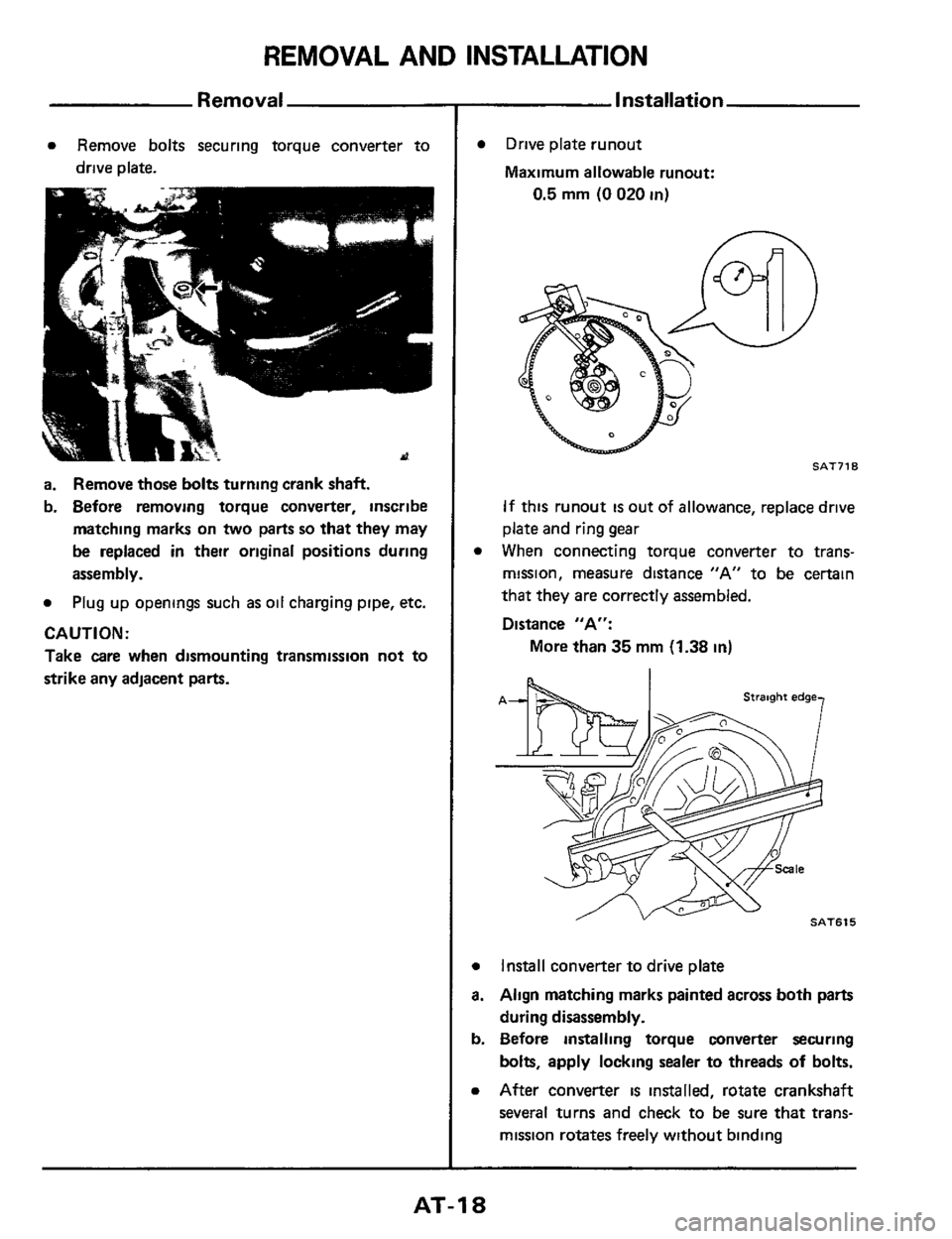
Removal
a Remove bolts securing torque converter to
drive plate.
a. Remove those bolts turning crank shaft.
b. Before removing torque converter, inscribe
matching marks on
two parts so that they may
be replaced in their original positions during
assembly.
a Plug up openings such as oil charging pipe, etc.
CAUTl ON :
Take care when dismounting transmission not to
strike any adjacent
parts.
Installation
0
a
a.
b.
a
Drive plate runout
Maximum allowable runout:
0.5 mm (0 020 in)
n
SAT718
If this runout is out of allowance, replace drive
plate and ring gear
When connecting torque converter to trans-
mission, measure distance "A" to be certain
that they are correctly assembled.
Distance "A":
More than
35 mm (1.38 in)
Install converter to drive plate
Align matching marks painted across both parts
during disassembly.
Before installing torque converter securing
bolts, apply locking sealer to threads
of bolts.
After converter is installed, rotate crankshaft
several turns and check to be sure that trans-
mission rotates freely without binding
AT-I 8
Page 22 of 99
DISASSEMBLY
1. Remove torque converter, drain A.T.F
through end of
rear extension, and place trans-
mission on
Tool.
v
SAT520
2 Remove lock-up solenoid (E4N71B).
3. Remove converter housing.
SATOW
4. Remove oil pan and inspect its contents. An
analysis of any foreign matter can indicate the
types of problems to look for. If the fluid
IS
very dark, smells burned, or contains foreign
particles, the frictional material (clutches,
band.) may need replacement. A tacky film
that will not wipe clean indicates varnish bulld
up which can cause valves, servo, and clutches
to stick and may inhibit pump pressure.
SAT006
5. Loosen 2nd band servo piston stem lock nut
and tighten piston stem.
If it turns more than
two turns, the band
is worn out.
SAT71 5
AT-22