1984 CHEVROLET CAVALIER light
[x] Cancel search: lightPage 24 of 105
Downloaded from www.Manualslib.com manuals search engine CAunOM: tf you need to tum oft the ... whikt the vehicte ls moving, turn the key only to "Oft." DO NOT depreSS the key release lever while turning the Ignition off._This
wln ·lock the steering column and result in loss arability to steer the vehlete.
If you have trouble turning the key to unlock the ignition, first be sure the key is
pushed in all the way . Then , try to turn the steering wheel as hard as you can .
in the direclioo the
wheels are tUrned . At the same ti me , turn the ignition kay
w~h as much eftort as you can apply with your hand. Do not try to use a tool of
any kind to
apply more force on the lock knob , as tnis could break the knob.
NOTICE: Do not park, idle, or operate your vehk:le over combustible materials, such
as grass or leaves . They couki touch the hot exhaust ay8tem and ignite.
Parking
CAUTION: Before the driver leaves this vehicle, to reduce the risk of personal injury ... resun of vehicle movement:
1. Firmly apply the parking brake.
2. Shift the automatic transtixle to Park or the manual tranSlale to "Reverse."
3. Tum the kef to "Lock. " On vehietn wrth manual transaxle$, __ ~ the key reiease tever and tum the key to·'Loclic. " .
4. Remove the key (the chime ia designed to remind you).
To reduce the chance of persona' injury and/or vehicle damage due' to engine overheating , never lellVe the engine Idling without an alert driver present. If the engine ahoukl overheat, as indicated by the Erlgine Coolant Temperature light Of gage,
Immediate action 1a required to correct the concIUon. Continued operation 01' the engine . enn FOA -A SHORT TtME may resutt In a fire.
TURN SIGNAL AND MULTI-FUNCTION LEVER
The turn signal lever on the left side of the steering column also controls headlight low-beam and high-beam, the windshield wiper/washer, and the
optional Cruise
Control. (See Cruise Control operatiOn in this section .)
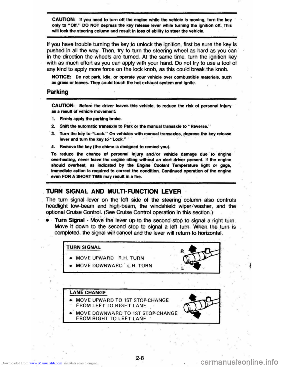
• TUI'fI Si!Jnal -MOve the lever up .to the second stop to signal a right turn.
Move
~ down to the second stop to signal a left turn. When the turn is
completed, the signal will cancel and the lever will return to horizontal.
TURN SIGNAL
• MOVE UPWARD R.H . TURN
• MOVE DOWNWARD L.H. TURN
LANE CHANGE
• MOVE UPWARD TO 1S T STOP·CHANGE
FROM LEFT TO RIGHT LANE
• MOVE DOWNWARD TO 1ST STOP ·CHANGE FROM RIGHT TO LEFT LAN E
2-8
Page 25 of 105
Downloaded from www.Manualslib.com manuals search engine • Lane Change Signal -In some turns, such as changing lanes, the steering wheel tS not turned far enough to cancel the turn signal. For convenience, you can flash the turn signal by moving the lever part way (to the first stop)
and holding it there. The lever will return to horizontal when you release it.
A green light on the instrument panel is designed to flash to tell you that the
front
and rear turn signal lights are working. If the light stays on, but does not flash, check for burned-out turn signal bulbs. If the green light does not come
on when
you move the lever, check the fuse and indicator bulb.
However, if you ordered a trailertowing·optiOil.·in which extra wiring was added to attach the trailer lighting, a different type of flasher was installed. In this
case, the green light will continue to flash even if a turn signal bulb burns out.
Therefore, you must regularly look at the front
and rear turn signal lights to be
sure they are working.
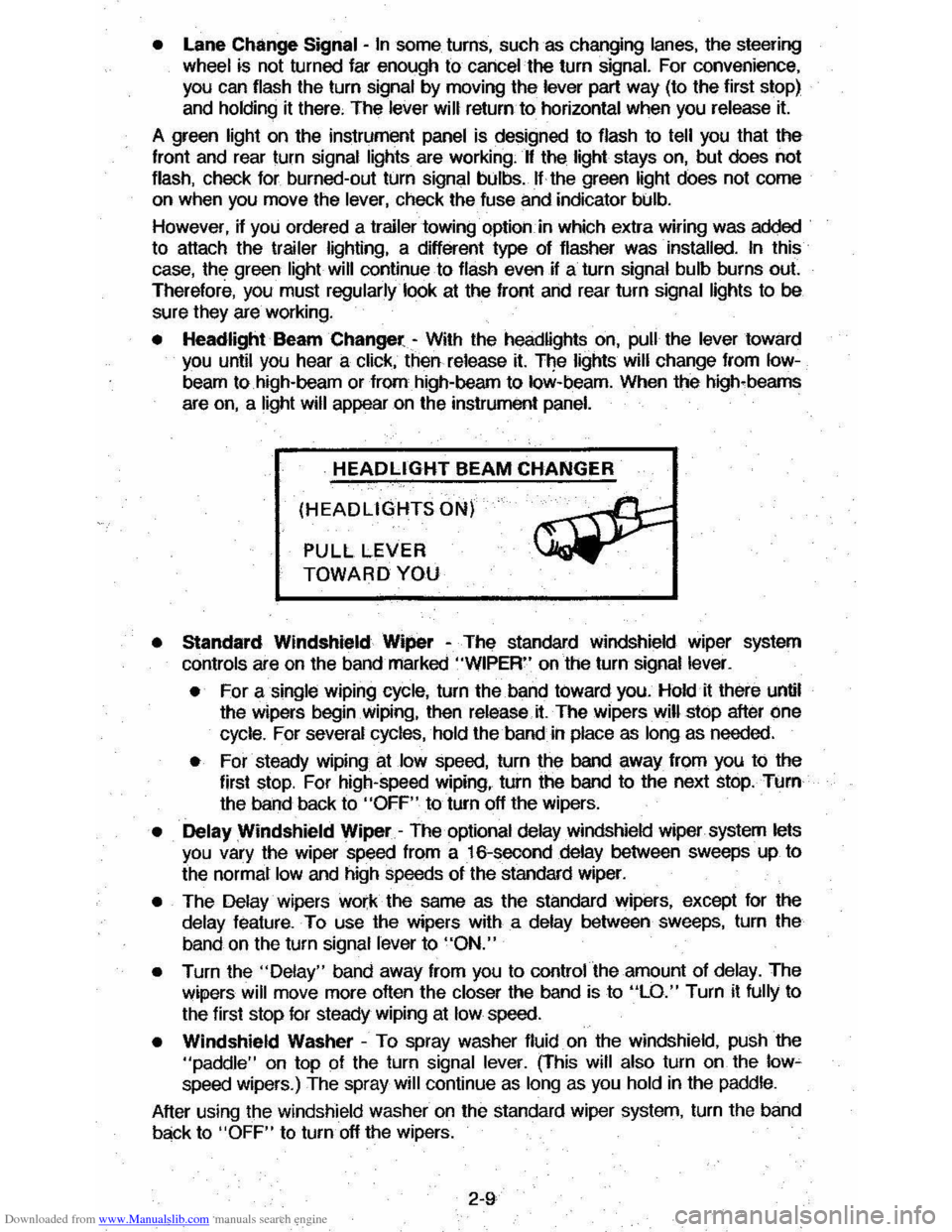
• Headlight Beam Changer -With the headlights on, pull the lever toward you until you hear a click, then release it. The lights will change from Iow
beam to high-beam or from high-beam to low-beam. When the high-beams
are
on, a light will appear on the instrument panel.
HEADLIGHT BEAM CHANGER
(HEADLIGHTS ON)
PULL LEVER
TOWARD YOU
• Standard Windshield Wiper -The standard Windshield wiper system
con
ols are on the band marked "WIPER" on the turn signal lever.
• For a single wiping cycle, turn the band toward you. Hold it there until
the wipers begin
Wiping, then release.it. The wipers will stop after one
cycle. For several cycles, hold the band in place as long as needed.
• For steady wiping at low speed, turn the band away from you to the
first stop. For high-speed wiping, turn the band to the next stop. Turn
the band back to
"OFF" to turn off the wipers.
• Delay Windshield Wiper -The optional delay windshield wiper system lets you vary the wiper speed from a 16-second delay between sweeps up to
the normal
low and high speeds of the standard wiper.
• The Delay wipers work the same as the standard wipers, except for the
delay feature. To use the wipers with a delay between sweeps, turn the
band on the turn signal lever to
"ON."
• Turn the "Delay" band away from you to control the amount of delay. The
wipers will move more often the closer the band is to "LO." Turn it fully to
the first stop for steady wiping at
low speed.
• Windshield Washer -To spray washer fluid on the windshield, pUSh the "paddle" on top of the turn signal lever. (This will also turn on the low~ speed wipers.) The spray will continue as long as you hold in the paddle.
After using the windshield washer
on the standard wiper system, turn the band
back to "OFF" to turn off the wipers.
2-9
Page 29 of 105
Downloaded from www.Manualslib.com manuals search engine ....rr -~
II'!
I~ ,
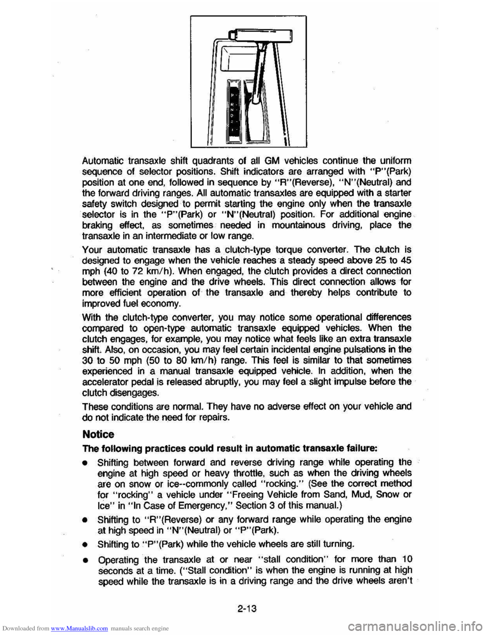
Automatic transaxle shift quadrants of all GM vehicles continue the uniform
sequence of
selector positions. Shift indicators are arranged with "P"(Park) position at one end, followed in sequence by "R"(Reverse), "N"(Neutral) and
the forward driving ranges. All automatic transaxles are equipped with a starter
safety switch designed to permit starting the engine
only when the transaxle selector is in the "P"(Park) or "N"(Neutral) position. For additional engine
braking eftect,
as sometimes needed in mountainous driving, place the
transaxle in an intermediate or low range.
Your automatic transaxle has a clutch-type torque converter. The clutch is
designed to engage when the
vehicle reaches a steady speed aibove 25 to 45 mph (40 to 72 km/h). When engaged, the clutch provides a direct connection
between the engine and the drive wheels. This direct connection allows for
more efticient operation of the transaxle and thereby
helps contribute to
improved
fuel economy.
With the clutch-type converter,
you may notice some operational differences
compared to open-type automatic transaxle equipped vehicles. When the
clutch engages, for example, you may notice what feels like an extra transaxle
shift Also, on occasion, you may feel certain incidental engine pulSi'tions in the
30 to 50 mph (50 to 80 km/h) range. This feel is similar to that sometimes
experienced in a manual transaxle equipped vehicle. In addition, when the
accelerator
pedal is released abruptly, you may feel a slight impulse before the
clutch disengages.
These conditions
are normal. They have no adverse effect on your vehicle and
do not indicate the need for repairs.
Notice
The following practices could result in automatic transaxle failure:
• Shifting between forward and reverse driving range while operating the
engine at high speed or heavy throttle, such as when the driving wheels
are on snow or ice--commonly called "rocking." (See the correct method
for
"rocking" a vehicle under "Freeing Vehicle from Sand, Mud, Snow or
Ice" in "In Case of Emergency," Section 3 of this manual.)
•
Shifting to "R"(Reverse) or any forward range while operating the engine
at high speed in "N"(Neutral) or "P"(Park).
•
Shifting to "P"(Park) while the vehicle wheels are still turning.
• Operating the transaxle at or near "stall condition" for more than 1 0 seconds at a time. ("Stall condition" is when the engine is running at high speed while the transaxle is in a driving range and the drive wheels aren't
2-13
Page 31 of 105
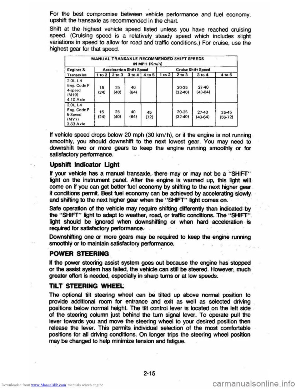
Downloaded from www.Manualslib.com manuals search engine For the best compromise between vehicle pertormance and fuel economy ,
upshift the transaxle as recommended in the chart.
Shift at the highest vehicle speed listed unless you have reached cruising
speed. (Cruising speed is a relatively steady speed whi ch includes slight variations in speed to allow for road andtrattic conditions.) For cruise , use the
highest gear for that speed.
MANUAL TRANSAXLE RECOMMENDED SH IFT SPEEDS IN MPH (Km/h) Engine$ & Accelera tion Shift S lllee! Crl.liM Shift S eed Trltn$ilxles 1 to 2 2to 3 3 to 4 4to 5 1102 2103 3104 4105 2 .0LUI E ng. Code P IS ,S 4. 20 ·25 "40 4-",,,", 124) (40) 164) (32401 (43.64) (M I9 ) 4.tOAxle 2.0L L4 EI1Q. Code P IS 26 4. 4S 20·25 27-40 35-45 5-Speed (24) (40) (64)
(72) 132·40) 143-64) (56-12) (MY7) 3.83 Axle
If vehicle speed drops below 20 mph (30 km/h) , or if the engine is not running .
smoothly , you should downshift to thE. next lowest gear. You may need to
downshift two or more gears to keep the engine running smoolhly or for
satisfactory performance .
Upshift Indicator Ught
H your vehicle has a manual transaxle. there may or may not be a "SHIFr" light · on the instrument panel. After the engine is warmed up, this light Will
corne on if you can get better fuel economy by shifting to the next higher gear
H conditions permit. !)est fuel economy can be achieved by acceleratingslQwly .
and shifting to the next higher gear when the "SHFT" light comes on.
Sale operation 01 the vehicle mayrsquire shifting differently lhan indicated by
the
"SHFT" light to adept to weather. rDild . or
affle conditions .. The ·"SHIFT '·
light should be ignored when downshifting or when hardaccelerallon Is required for satisfactory performance.
Downshifting one or more gears may be required to keep the engine .running
smoothly or
to maintain satisfactory performance ;
POWER STEERING
N the power steering assist system goes out because the engine has stopped
or the assist system has failed. the vehicle.can still be steered . However ; much greater effort Is needed . especially in sharp turns or at low speeds;
nL T STEERING WHEEL
The optional lilt steering wheel can be tilted up above normal position to
provide additional roorn for entrance and exit as
well as selected driving
positions
below normai height. The tilt control lever is located on the left side
of the steering column just behind the turn signal lever. To operate pull the
lever towards you and move the steering wheel to your· desired position then release the lever. This permits individual selection of Ihe mostcornfortable
positions for all driving cond itions . On longer trips the steering wheel position may be changed to help minimize tension and fatigue.
2-15
Page 32 of 105
Downloaded from www.Manualslib.com manuals search engine CRUISE CONTROL WITH RESUME/ACCEL FEATURE
Cruise Control is an optional speed control system. The system allows the vehicle· to keep a constant forward speed during most normal driving without
keeping your foot on the accelerator pedal, thus increasing driver comfort on
long trips. The system
can hold a speed of about 30 mph (50 km/h) or higher
within the limits of your engine.
The
system is also designed to resume a pre-set cruising speed after:
• Braking. clutching with manual transaxle vehicles, without using the
accelerator pedal.
•
Accelerating from a given set speed to a higher control speed.
The system also allows the driver to "Tap-up" and increase speed or "Tap
down" to decrease vehicle speed in increments of about 1 mph (1.6 km/h)
when needed. This feature is useful when traffic conditions warrant a small
adjustment in speed. The controls are part of the turn signal lever. The
"Cruise" switch must be moved to "On" before the system will work. The "Set/Coast" button is in the end of the turn signal lever.
To Engage at Cruising Speed
Accelerate to the desired speed, push in the "Sel/Coast" button all the way
and release it (or use the "Resume/ Accel" (R/ A) switch during first
engagement only). Take your foot off the accelerator pedal and the set speed
will be maintained up Qr down hill. The Cruise Control is designed to disengage
when you apply the brakes and also with the clutch on manual transaxle
vehicles.
It will also disengage by moving the "Resume/ Accel" (R/ A) switch to
off or by turning the ignition off. (To disengage the system without coming to a
complete
stop, push the brake pedal or clutch lightly; use just enough force to
disengage the system, witi)out stopping the vehicle:)
To Change Cruising Speed
To reset the Cruise Control to a faster speed, accelerate to the speed you wish. Push in the "Set/Coast" button all the way, (for less than a second) then release it.
Or, use the "Resume/ Aceel" switch to accelerate and reset to the speed you
wish. The "Resume/ Accel" (R/ A) switch must be held (over a second) in
order to engage the accel mode. Speed may also be increased by tapping the
"Resume/
Accel" switch for less than a second while cruising. The set speed
will
be increased by about 1 mph (1.6 km/h) for every tap. "Tap-ups" are
limited to 10 mph (16 km/h) above vehicle speed.
To reset to a
slower speed, push in the "Set/Coast" button all the way and hold it there. Wait until the vehicle slows to the desired speed, then release the
button.
Speed may also be decreased by tapping the "Sel/Coast" button for less than a second while cruising and the memory speed will be decreased
about 1
mph (1.6 km/h) for every tap, "Tap-downs" are limited to a minimum
cruising speed of 23 mph (37 km/h).
To "Resume" a Pre-Set Speed
After braking or stopping the vehicle without turning off the ignition, you can "resume" to your last set cruising speed by accelerating to 30 mph (50 km/h)
or more
and sliding the cruise switch momentarily to "Resume/ Accel"; when
you release the "Resume/ Accel" switch, your vehicle will accelerate to the
cruising speed set before braking or stopping.
2-16
Page 34 of 105
Downloaded from www.Manualslib.com manuals search engine When_ going up or down hills. it ~ ~ tor the vehk:1e to toM 011 to gain apHCI (.,.rticu"Y when towing I trailer), even though the Cruise Control is enpgecL • this happens while going up hin, merely depress the accelerator pedal to maintain the speed desired. If going down a hili steep enough to cau .. thl vehie'" to gain speed, depress the brake pedal •• which will both dl .. ngage the Cruise Control and help .lOw the vehicle. In addition, when going down a steep or lang grade . the transaxle shoUld be shifted into I lower gear to help control vehicte speed •• see "Descending A Grade " in "Starting and Operating," Section 2.
HORN
The horn on your vehicle is actuated by firmly pressing on the ped in the
center of the steering
wheel.
HAZARD WARNING FLASHER
The hazard warning flasher is covered in "In Case of Emergency," Section 3.
FLOOR CONTROLS
BRAKING SYSTEM
The regular braking system is designed for braking performance under a wide
range of driving cond~ions even when the vehicle is loaded to ~ lull rated
vehicle toad capacity .
CAUTION: Driving through water deep enough to wet brake components may cau .. the brakea nat to work .. welL -M a reaul, the vehIde wi. not aIow down .. the usu.I _, ond M may pull 10 "'" right Of ..... _ 0"'-""'11 to "'" _ tor _ .-.os,
-'1 "'" ...... lightly 10 check __ .... "-'"
Brake Warning lJg/rt
The brake system warning light is covered in the '.' lnstrumentPanel" section.
Vacuum Power Brakes
• the engine stops, do not pump the brakes. The system is designed to stop the vehicle with reserve power assist n the brake pedal is held dOwn. This
reserve is
greatly reduced each time you apply and release the brakes. II,
when you turn the atMring wheel during braking, the vehic:1e does not turn, don't push as hard on the brake pedal •.
Without power assist the vehicle can still be stopped by pushing much harder
on the brake
pedal. however. the stopping distance may be longer.
Brakes (Except ,Parking Brake)
H the brake pedaJ goes down farther than normal, ~ may be due to a lack of
adjustment of any rear drum
brakes. To find. out if this is the case. drive
backward and forward a few times. applying the brakes firmly when going in
each direction.
See your dealer n pedal height dOes not retum to normal, or there is a rapid
increase in pedal travel whether or not your vehicle has rear drum brakes. This
could be a sign of brake trOUble.
NOTICE: "FtidInsI the brake" by resting yow i0oi on thl brau pedal when you do not Intend 'to brake CIIf1 overhMI: the brIkM and ...... out the brake InInga and p..ts faster. , ThI. mIIy alSo dllNlge the brakes Mtd will wasta fuel.
2-18
Page 35 of 105
Downloaded from www.Manualslib.com manuals search engine PARKING BRAKE
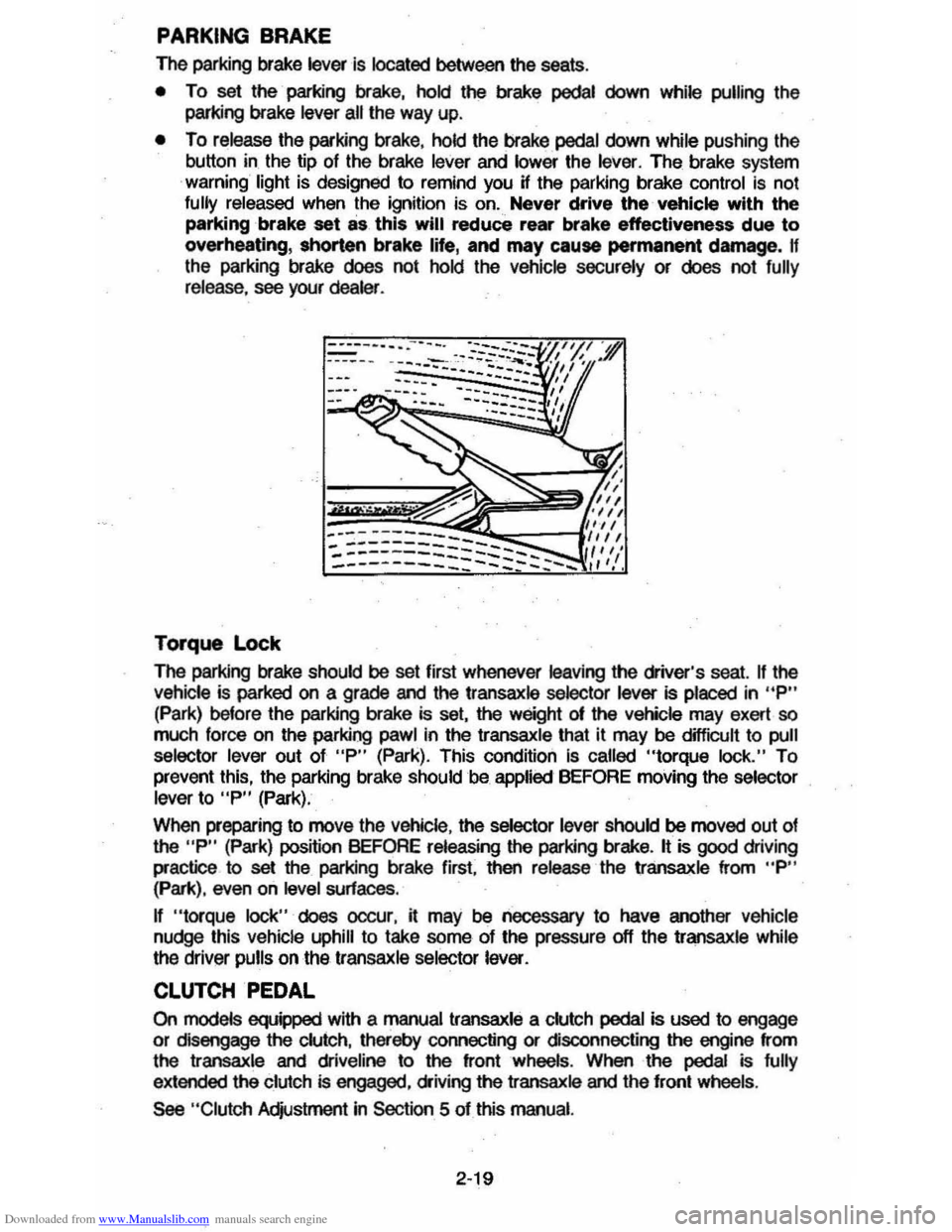
The parking brake lever is located between the seats .
• To set the parking brake, hold the brake pedal down while pulling the
parking brake
lever all the way up.
• To release the parking brake, hold the brake pedal down while pushing the
button in the tip of the brake
lever and lower the lever. The brake system
warning light is designed to remind you H the parking brake control is not fully released when the ignition is on. Never drive the vehicle with the
parking brake set as this will reduce rear brake effectiveness due to
overheating, shorten brake life, and may cause permanent damege, If
the parking brake does not hold the vehicle securely or does not fully release , see your dealer .
Torque Lock
The perking brake should be set first whenever leaving the driver's seat. If the vehicle is parked on a grade and the transaxle selector lever is placed in "P"
(Park) before the parking brake is set, the weight 01 the vehicle may exert so
much force on the parking pawl in the transaxle that it may be difficult to pull
selector lever out of "P" (Park). This condition Is called "torque lock." To
prevent this, the parking brake should be applied BEFORE moving the selector lever to "P" (Park).
When preparing to move the
Vehicle , the selector lever should be moved out of the "P" (Park) position BEFORE releasing the parking brake. It is good driving
practice to
set the parking brake first. then release the transaxle from "P" (Park), even on level surfaces .
n "torque lock" does oocur, it may be necessary to have another vehicle
nudge this vehicle uphill to take some of the pressure off the transaxle while
the driver pulls on the transaxle selector lever.
CLUTCH PEDAL
On models equipped with a manual transaxle a clutch pedal is used to engage
or disengage the clutch, thereby connecting or disconnecting the engine from
the transaxle and dliveline to the front wheels . When the pedal is fully
extended the clutch is engaged, driving the transaxle and the front wheels .
See "Clutch Adjustment in Section 5 of this manual.
2·19
Page 36 of 105
Downloaded from www.Manualslib.com manuals search engine DISC BRAKE WEAR INDICATORS
Front disc brake pads have buin-in wear indicators which should make a high
pitched squealing or cricket-like warning sound when the brake pads are worn
to where new pads are needed . The sound will oome and
go. or be heard all the time when the vehicle is moving and when the brake pedal is pushed down
firmly. Expensive rotor damage can result if pads are not replaced when needed. See also the brake checks listed in the Maintenance Schedule folder.
INSTRUMENT PANEL AND CONTROLS
INSTRUMENTS
The instruments . gages and indicator lights conveniently grouped in the
instrument
cluster are designed to tell you at a glance many important things
about the performance of your Vehicle . The following information will enable
you to more quickly understand and properly interpret these instruments.
Speedometer
The speedometer hand indicates vehicle speed in miles per hour and
kilometers per hour.
Odometer
The group of figures in' the speedometer lower center section indicates the
accumulated mileage or kilometers .
Tamper-Resistant Odometer
Federal law prohibits tampering with vehicle odometers to aner accumulated
mileage. For your protection the odometer of this vehicle is designed with
tamper-resistant features to indicate
tarnpetiog . " silver lines appear vertically
between odometer numerals. it Is likely that the odometer has been turned
back or reversed . The mileage shown may not be actual. .
Whenever a new odometer is installed and cannot be set to the same mileage registered on the prior odometer . the law requires the owner to install a label
on thedriver's door frame to show the previous odometer reading and the date
of rep~. The · replacement odometer must then be set to zero . To
determine the actual vehicle
mileage. add the mileage shown on the label to . the current odometer reading. If the replacement odometer can be set up to
the same mileage as the prior odometer. no door frame
label is needed.
Trip Odometer
A trip odometer is used to record mileage on trips or during extended driving.
The trip odometer can be reset to zero by pushing the knob located in the
speedometer /odometer face until all zeros appear.
Fuei Gage
The fuel gage will register the APPAOXIMA TE fuel level in the tank. when the
ignition is in the RUN position .
When the gage registers EMPTY. some
fuel is still available as a reserve .
When the gage registers FULL. some additional fuel can still be added to the
tank . The fOllowing oonditions may be oonsidered normal:
•
Fuel station pump may shut off before fuel gage indicates FULL .
2-20