1984 CHEVROLET CAVALIER check engine light
[x] Cancel search: check engine lightPage 38 of 105
Downloaded from www.Manualslib.com manuals search engine Have the system repaired n the "CHECK ENGINE" light does not come on during engine starting. If the light comes on, either intermittently or
continuously while driving, service to the Computer Command Control system
is required. AHhough in most cases the vehicle is drivable, and does not
require towing, see your authorized
dealer as soon as possible for service of
the system.
Continued driving without having the Computer
Command Control system serviced could cause damage to the emission control system. It could also affect fuel economy and drivability.
See also "Computer Command Control system" in Section 5 of this manual.
Brake System Warning Light
The regular braking system is a dual system designed so that one part will
provide some braking if there is a
loss of hydraulic pressure in the other part of
the system. The system has a
"BRAKE" warning light located in the
instrument panel. The "BRAKE" light is designed to come on briefly during
engine starting so you can check that the bulb is okay. To serve as a reminder,
the
light should stay on when the parking brake is not fully released and the
ignition is
on. Have the system repaired if the light does not come on when it should. This warning light does not do away with the need for brake inspection
and maintenaflce. The brakelluid level must be checked regularly. See your
Maintenance Schedule folder for other brake checks.
I! the light remains on aller engine start up or comes on during operation of the vehicle, it may mean that there is something wrong with part of the brake
system.
What
to do:
1. Check to see that the parking brake has been released. I! it has been:
2. Pull off the road and stop carefully. Remember that:
• Stopping distances may be longer.
•
You may have to push harder on the pedal.
•
The pedal may go down farther than normal.
3. Tryout the brakes by starting and stopping on the road shoulder--then:
• I! you judge it to be safe, drive cautiously at a safe speed to the
nearest dealer for repair. Or,
• Have vehicle towed to the nearest dealer for repair.
Continued driving without getting necessary repairs
could be dangerous.
Tachometer
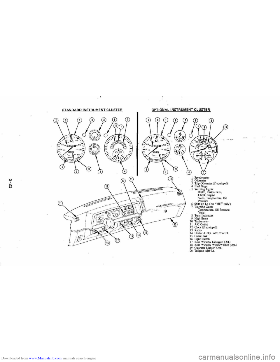
The optional tachometer indicates the speed of the engine in revolutions per
minute. The indicated number, times
100, gives the engine speed. Operating
the engine with the tachometer reading in the color-coded high-speed area
could lead to serious engine damage.
Voltmeter
When the engine is operating, the voltmeter indicates the electrical system
voltage. During minimum electrical load, the pointer will read to the right of the
center.
As the electrical load is increased, or in stop-and-go driving, the pointer
will rotate to the Ieli. A meter reading continuously in the left or right zone
indicates
an electrical system failure. Cause of the failure should be determined and corrected.
2-22
Page 39 of 105
Downloaded from www.Manualslib.com manuals search engine '" ,
t:l
STANDARD INSTRUMENT CLUSTER
IJ
12
OPTIONAL INSTRUMENT CLUSTER
~~~~-:'----,~~:
l'l
1l
10
L Speedometer 2. Odometer 3. Trip ()jometer lif equipped) 4. Fuel Gage 5. Warning Lights Brake, Fasten Belts, Check. Engine Volts, Temperature, Oil Pressure 6. Shift up Lt. (on "ME"only) 7. Warning Gages Temperature, on Pressure, Volts 8. Turn Indicators 9. High Beam 10. Tachomet er 11. A/C Outlet 12. Clock. (if equipped) 13. Radio 14. Heater & Opt. Ale Control 15. Glove Box 16. Lig ht Switch 17. Rear Window Defogger (Opt.) 18. Rear Window WiperlWasher (Opt.) 19. Cigare tt e Lighter (Opt.) 20, Tailgat e Ajar Lt.
Page 40 of 105
Downloaded from www.Manualslib.com manuals search engine Engine Coolant Temperature Gage
This optional gage is located in the instrument cluster. If the gage shows that
an overheat condition exists-as indicated by pointer moving beyond the
center of the band immediate action by the driver is required. If an overheat
condition is shown, see "Engine
Cooling System Overheating" in "In Case of
Emergency,"
Section 3 of this manual. The coolant temperature indication will VaIY with air temperature and operating conditions. The ignition must be in
"Run" for accurate readings. Prolonged driving or idling in very hot weather
may cause the pointer to move beyond the center of the gage. Make a practice
of scanning this and other gages
while driving, especially in hot weather and!
or when the
vehicle is under load.
CAUTION: II the Engine Coolant Temperature Gage shows an overheat condition or you have other reason to suspect the engine may be overheating, continued operation of the engine EVEN FOR A SHORT TIME may result in a fire and the risk of personal injury and/or severe vehicle damage. Take immediate action as outlined under "Engine Cooling System Overheating" in "In Case of Emergency," Section 3.
Oil Pressure Gage
The oil pressure gage indicates the pressure at which oil is being delivered to
the vaIiOUS paIls of the engine requiring lubrication. Pressures registered by
the gage may
vBIY according to outside air temperatures or weight of oil being
used. Oil pressure of a cold engine being operated at a given speed will be
somewhat higher than when the engine is at normal operating temperature at
the
SaIne speed. Prolonged high speed operation on a hot day at the given
speed will
resuH in somewhatlower oil pressure readings. Readings of 205 to
275 kPa
(30 to 40 psi) may be considered normal during moderate road
speeds of 35 to 40 mph (55 to 60 km!h) with the engine at proper operating
temperature. Gage readings which are consistently high
or low under these conditions may indicate lubrication system and/ or engine malfunction.
Light Switch
The three· position light switch controls the headlights, taillights, paIking lights,
sidemaIker lights,
instrument lights and dome lights.
Instrument light intensity can be varied by turning knob clockwise or
counterclockwise. Full counterclockwise position turns on interior light.
The headlight circuit is protected by a circuit breaker in the
light switch. An overload on the breaker will cause the lights to "flicker" on and off. If this
condition
develops, have your headlight wiring checked immediately. The
headlight beaIn changer is located in the Turn Signal Lever; for operation see
Section 2 under heading "Turn Signal and Muiji-Function Lever."·
Headlight High Beam Indicator Light
The headlights of your vehicle have. high and low beams to provide you with
proper nighttime visibility for most driving conditions. The
"low" beams are
used during most city driving. The
"high" beams are especially useful when
driving on daIk roads since they provide long range illumination. The headlight
beam indicator light (located on the speedometer face) will be ON whenever
the high beams or "brights" are in use. The turn
signal lever controls the
headlight beaIns and is described in "Steering Column Controls."
2-24
Page 52 of 105
Downloaded from www.Manualslib.com manuals search engine • Adjust the heating or cooWng system to force outside air into the cal as
follows :
1. On cars not equipped with air conditioning , set the fan to high speed
and the upper control lever to any position except "Off."
2 . On cars equipped with air condition ing, set the fan to high speed and
the
upper control lever to any position except "Off" or "Max."
• On cars that have outside air vents in or under the instrument panel, open
vents
fully .
"Gate Ajar" Ught
Station wagons have a "GATE AJAR" warning light located in the instrument
cluster . It is designed to come on ~ the liftgate is not lully closed and the
ignition is on , thus warning against driving with the liftgate even partially open.
See "Engine Exhaust Gas Caution (Carbon Monoxide)" at the beginning 01
"Starting and Operating ," Section 2 of this manual . To test that the ight circuit
is working correctly , start the car and check that the light comes on when the liftgate is open or only partially latched.
Electric Trunk, Hatchback , Or Tailgate Release
An electric release permits opening the trunk, hatchback or station wagon tailgate from inside the car by pressing a release bunon in the instrument panel
glove box. The release lor the hatchback and the station wagon tailgate will
function only II the automatic transaxle is in "P" (Park) or "N" (Neutral) or, on
manual transaxle cars, ~ the parking brake is applied .
SUNSHADE (OPTIONAL)
n your hatchback model is equipped with the optional louvered rear window
sunshade, the
sunshade·is hinged at the top and heid down at the boUom by a
one-quarter tum fastener on each end of the sunshade. This method of
attachment
allows you to raise the sunshade lor cleaning the exterior of the
hatchback glass :
To clean the hatchback lid exterior glass:
1. Using a coin or screwdriver , rotate each lastener one-quarter turn until they pop up; the sunshade is now unlocked .
2. Grasp the lower edge 01 the sunshade approximately in the middle and lift
the sunshade away Irom the hatchback lid.
3. Clean the hatchback glass as desired while holding the sunshade in the
open position.
4 . Lower the sunshade to
its original position and locate the one-quarter turn
fasteners over the holes in the lower bracket assemblies; using a coin or
screwdriver, push the one-quarter turn stud downward
until it engages the
wire bail on the bracket and rotate one-quarter turn to lock. (Make sure the
lastener is
locked to the bracket by. lifting each corner 01 the sunshade.)
NOnCE: DO NOT DRIVE when sunshade is not lOcked in position.
To remove the sunshade from the car, ~ desired , release the sunshade as you would lor cleaning. Then, remove the four nuts which secure the sunshade
hinges to the hinge base
plate on the hatchback lid. Wft the sunshade assembly from the car.
2-36
Page 53 of 105
Downloaded from www.Manualslib.com manuals search engine To store the sunshield when rennoved from the car, always select a place
where the sunshade can lay flat without anything stored on top of it or leaned against it. Hanging the sunshade flat on a wall by its hinges is an excellent way
to store it.
As with any decorative surface. washing with a mild soap and water solution is
recommended . Abrasive materials or chemical solvents may adversely affect
the finish of the sunshade.
FOLDING SEATBACK OPERATION
Station wagon and hatchback models are equipped with either a one-piece or split folding rear seatback which is not designed to lie flat, but does provide
additional load floor area when lowered .
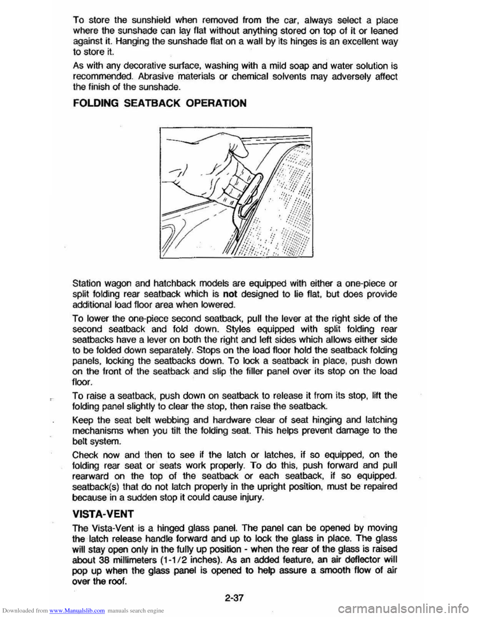
To lower the one-piece second seatback, pull the lever at the right side of the
second seatback and fold down. Styles equipped with split folding rear
seatbacks have a
lever on both the right and left sides which allows either side
to be folded down separately . Stops on the load floor hold the seatback folding
panels. locking
the seatbacks down. To lock a seatback in place, push down on the front of the seatback and slip the filler panel over its stop on the load
floor .
To raise a seat back. push down on seatback to release it from its stop. lift the folding panel slightly to clear the stop, then raise the seatback.
Keep the seat
belt webbing and hardware clear of seat hinging and latching
mechanisms when you @ the folding seat. This helps prevent damage to the
belt system.
Check now and then
to see if the latch or latches, if so equipped, on the folding rear seat or seats work properly. To do this, push forward and pull
rearward on the top of the seatback or each seatback, if so equipped.
seatback(s) that
do not latch properly in the upright position. must be repaired
because
in a sudden stop rt could cause injury.
VISTA·VENT
The Vista-Vent is a hinged glass panel. The panel can be opened by moving
the
latch release handle forward and up to lock the glass in place. The glass
will
stay open only in the fully up position -when the rear of the glass is raised
about 38 mimmeters (1-1/ 2 inches) . As an added feature, an air deflector will
pop up when the glass panel is opened to help assure a smooth flow of air
over the roof.
2·37
Page 57 of 105
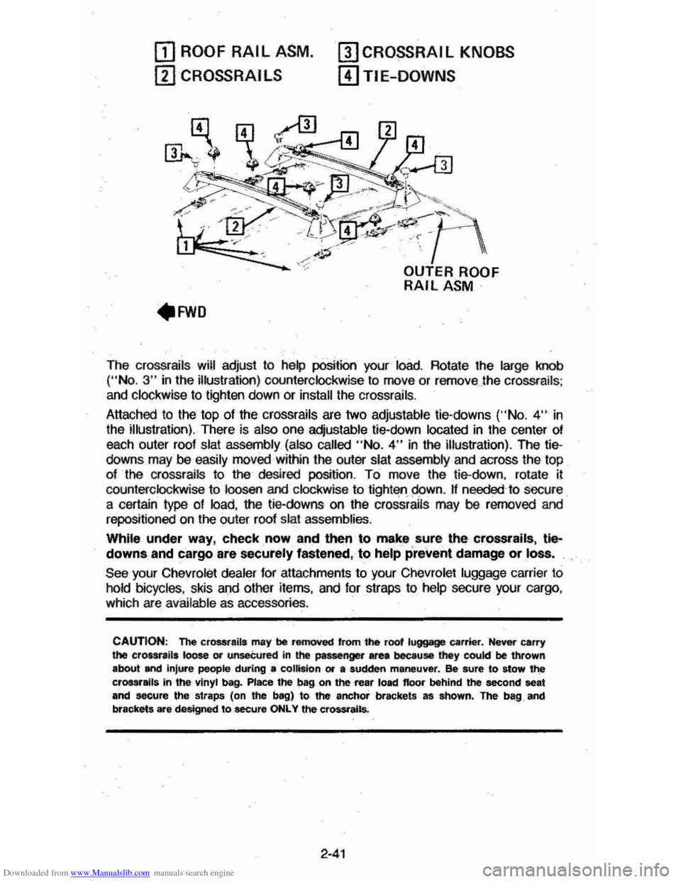
Downloaded from www.Manualslib.com manuals search engine OJ ROOF RAIL ASM.
ill CROSSRAI LS
mCRO~RAIL KNOBS
[!)TIE-DOWNS
The crossrails will adjust to help position your load. Rotate the large knob ("No.3" in the illustration) counterclockwise to move or remove . the crossrails ;
and clockwise to lighten down or install the crossrails .
Attached to the top
of the crossrails are two adjustable tie-downs ('·No. 4" in
the illustration). There is also one adjustable tie-down located in the center of
each outer roof
slat assembly (also called "No.4" in the illustration). The tiedowns may be easily moved within the outer slat assembly and across the top
of the crossrails to the desired position. To move the tie-down, rotate il
counterclockwise to loosen and clockwise to tight'lfl.95>wn. If needed 'to secure
a certain type of load, the tie-downs on the crossrails may be rerncved and
repositioned on the outer roof slat assemblies.
While under way, check, now and then to make sure, the crossrails, tle~
downs, and cargo are securely fastened, to help prevent damage or loss.
See your Chevrolet dealer for attachments to your Chevrolet luggage carrier to
hold bicycles, skis and other items, and for straps to help secure your cargo ,
which are available as accessories .
CAUTION: The cr0SSt8ils may be removed 'rom the root luggage carrier. Never carry the crour,ils loose or unseCured in the passenger area because they cookr be thrown
about and injure people during .. collision or a sudden maneuver. ee sure to stow t~ crossralla in the vinyl bag. Place the bag on the rea, load floor behind the second seat and secure the straps (on the bag) to the anchor brackets as ahown. The bag, and
brackets are designed to secure ONLY the crossrails.
2-41
Page 65 of 105

Downloaded from www.Manualslib.com manuals search engine 3. Install wheel and tire assembly and install hub cap by pushing or hitting
into place (the wheel can be mounted with hub cap in place). The hub cap
must be oriented by engaging the bump on the side of the hub cap
retention tab with the cutout on the side of the wheel pilot hole.
Compact Spare
The compact spare tire is designed to save space in your stowage area, and
its lighter weight makes it easier to install if a flat tire occurs. The lighter weight also helps improve fuel economy. ~--~------~~
" you have a flat tire, follow the jacking Instructions in this section, while keepingihese points in mind:
• Check the tire inflaiionpressureas soon as practical after installing the
spare (we suggest you use a 'pocket-type high'pressure inflation gage) and
adjust the pressure to 415
kilopascals (60 pounds per square inch). The
tire pressure should be checked at least monthly and kept at 415 kPa (60
psi) while the tire is stored . Also at least monthly , ·qheck that the spare lire is stowed securely ; tighten it if ~ is not.
NOTICE: Bee ... this tire is smaller than the standard tire, vehicle ground clearance is reduced. Do not take your vehicle through an automatic car wash while ~ spare I. Installed; the vehicle may catch on the equipment, possibly resulting In property damag_.
• YOU can expect a tread life up to 3,000 miles (4 800 kilometers), dependiQg on road conditions and your driving habits. The tire was designed to let you
finish an extended trip (up to 3,000 miles/4 800 kilometers) and buy a replacement tire, -if needed, at a store of your choice. However, to conserve
tire tread ~fe, return the spare to the stowage area as' soon as it is
convenient to have your standard tire repaired or replaced.
• Because the compact spare was specnically designed for your vehicle , ~ should not be used on any other vehicle.
• The compact spare tire and wheel are designed for use with each other.
The compact spare tire should not be mounted on any other type of wheel, and the compact spare wheel should not have any other type of tire
mounted on it. Also, do not try to use wheel covers or trim rings on the
CQr1l>aCt spare whe el since they will not fit. If such use is attempted,
damage to tIlese items or other vehicle components may occur.
• Do not use tire chains with your :compact spare tire. Because of the smaller tire size, a tire chain will not fit properly. This could cause damage to the
vehicle and result in loss of the chain.
3-7
Page 75 of 105
Downloaded from www.Manualslib.com manuals search engine NOTICE: H you need to replace the fuel cap, use only a cap specified for your model. An incorrect fuel cap can result in a serious maHunction of the fuel system or emission control system. You can get a correct replacement cap from your dealer.
CATALYTIC CONVERTER
The catalytic converter is an emission control device added to the exhaust system to reduce exhaust gas pollutants. The converter contains
a ceramic material coated with noble metal catalysts. To prevent contamination
and loss of effectiveness of the catalysts. unleaded gasoline must be used.
Unleaded
gasoline also reduces spark plug fouling, exhaust system corrosion and engine oil deterioration. Leaded gasoline will also damage the oxygen
sensor
in the Computer Command Control system which could affect emission
control.
To help prevent damage:
1. Keep your engine properly maintained. Engine malfunctions involving the
electrical, carburetion, electronic fuel injection or ignition systems may
result in unusually high catalytic converter and exhaust system
temperatures which, under extreme malfunctioning conditions, may ignite
interior floor ·covering materials above the converter. Do not keep driving
your vehicle if you detect engine misfire, noticeable loss of
performance, or other unusual operating conditions. Instead, have it
serviced promptly. See the Maintenance Schedule folder for information on inspecting and maintaining the engine, exhaust system, and other
components.
2. Do not push or tow this vehicle to start it. This may result in unusually
high catalytic converter
and exhaust system temperatures which under
extreme conditions may ignite interior floor-covering material above the
converter.
Disregarding these instructions
could damage the catalytic converter, the vehicle, or nearby property and affect warranty coverage.
COMPUTER COMMAND CONTROL SYSTEM
Most vehicles sold in the United States (and some vehicles sold in Canada)
have the Computer Command Control system.
The Computer Command Control system monitors the exhaust stream with
an oxygen sensor. Based on sensor signals, the electronic control module adjusts
the air-fuel ratio
as needed. It is very important to use only unleaded
gasoline in vehicles equipped with the Computer Command Control system.
Leaded gasoline will damage the oxygen sensor,
and may affect emission
control.
"Check Engine" Light
Most vehicles sold in the United States (and some vehicles sold in Canada)
have the Computer Command Control system.
Vehicles
.with the Computer Command Control system, include a "CHECK
ENGINE" light
on the instrument panel designed to indicate the need for
system service. It will come on during engine starting to let you know the bulb
is working. (The
light will stay on a short time aiter the engine starts.) Have the
system repaired if the "CHECK ENGINE" light does not come on during engine
starting.
If the light comes on, either intermittently or continuously while driving,
service to the Computer Command Control system is required. Although in
5-2