1984 CHEVROLET CAVALIER air condition
[x] Cancel search: air conditionPage 42 of 105
Downloaded from www.Manualslib.com manuals search engine Operating Tips
• Clear snow and ice from the hood and air inlet in front of the windshield . This helps the heater and defroster work better and reduces the chance 01 fogging the inside 01 the windshield .
•
Run the blower on "HI" for a few moments belore driving off. This helps
clear the intake ducts of snow and moisture and reduces the chance of
logging on the inside
01 the windows.
• Always keep the front inlet grilles clear of obstructions (leaves, ice, snow ,
etc .) .
• Always keep the underseat air path clear of objeCts .
Lower Air Vents
Two control handles located beneath the center instrument panel open (pull)
and close (full in ) the lower "ram " air vents. The amount of air discharged at these lower ·outlets increases with vehicle speed. Maximum airflow can be
obtained by opening any of the .side door windows approximately six inches. If so equipped, the rear quarter swing-out windows will"optimize lower vent
performance and provide maximum airflow without opening a side door glass . In this condition, minimum air buffeting and road noise is incurred.
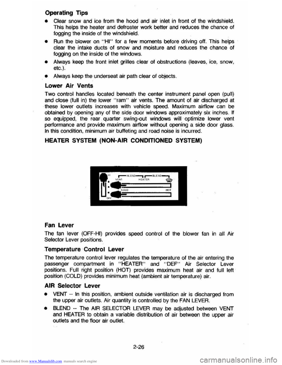
HEATER SYSTEM (NON-AIR CONOmONEO SYSTEM)
Fan lever
The fan lever (OFF-HI) provides speed control of the blower fan in all Air Selector Lever pOSitions.
Temperature Control lever
The temperature control lever regulates the temperature 01 the air entering the
passenger compartment in
"HEA TEA" and " DEF " Air Selector Lever
positions . Full right position (HOT ) provides maximum heat air and full left position (COLD) provides minimum heat (ambient air temperature) air.
AIR Selector lever
• VENT --In this position, ambient outside ventilation air is discharged from the upper air outlets . Air quantity is controlled by the FAN LEVER.
• BLEND --The AIR SELECTOR LEVER may be adjusted between VENT and HEATER to obtain a variable distribution of air between the upper air outlets and the floor air outlet.
2-26
Page 43 of 105
Downloaded from www.Manualslib.com manuals search engine • HEATER --In this position, most of the air is delivered to the floor air outlet
with a small amount delivered to the windshield (defroster outlets). The air
temperature
Is controlled by the TEMPERATURE LEVER while the air
quantity
is controlled by the FAN LEVER. This position is used for most winter driving.
• BLEND -- The AIR SELECTOR LEVER may be adjusted between HEATER
and DEFROST positions to obtain a variable distribution of air between the
floor air outlet and the windsh ield defroster air outlets.
• Side window defogger air outlets direct air to the side windows whenever
the fan is operating.
•
DEFROST - -In this poSition, most of the air is delivered to the windshield
(defroster outlets) with a small amount
to the floor air outlet.
The windshield defrosting and defogging system assists in providing
good visibility through designated areas of the windshield under most inclement
weather conditions . For immediate operation of the vehicle, the windshield
should be scraped clear.
Operate system for 30 seconds before switching to DEFROST . This will
remove humid air from the system
and minimize rapid fogging of the glass
which can occur if humid air Is blown onto a cOol windshield .
AIR CONOmONING SYSTEM
This system combines heating and cOOling capabilities for comfort in all weather conditions.
During some air conditioning operating conditions, slight increases and
decreases of engine speed/power may be noticed . This
should be considered
normal, as the system is designed to cycle the compressor
ON and OFF to
maintain desired cooling. The reduced compressor operation should
benef~ fuel economy.
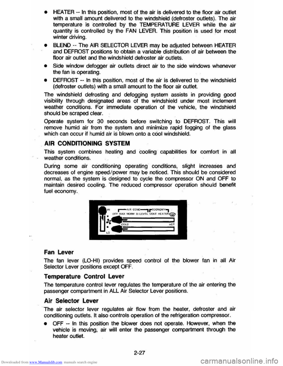
Fan Lever
The fan lever (LO-HI) provides speed control of the blower fan in all Air
Selector Lever positions except
OFF.
Temperature Control Lever
The femperature control lever regulates the temperature of the air entering the passenger compartment in All Air Selector Lever positions .
Air Selector Lever
The air selector lever regulates air flow from the heater, defroster and air
conditioning outlets.
It also controls operation of the refrigeration compressor.
•
OFF --In this position the blower does not operate . However, when the
vehicle is moving, air will enter the· passenger compartment through the
heater outlet.
2-27
Page 44 of 105
Downloaded from www.Manualslib.com manuals search engine • MAX (AIR COND) --Air from the passengel' cOlTlpaftment is mixed with a small amount of outside air. conditioned and discharged from !he upper
outlets . This position. with the temperature
lever in full COLD. is used for
maximum cooling under conditions of high temperature and humidity .
• NORM (AIR COND) --Outside air is conditioned as ~ passes through the
system and is discharged from the upper outlets. This position is used for most air conditioning situations.
• BI-LEVEL (AIR COND) --Outside air is conditioned and directed out the
upper outlets PLUS the heater outlet. This position provides comfort and
keeps the windshield clear under low fogging conditions .
• VENT (ECONOMY) --Outside air is discharged from the upper outlet s. This position is provided for cool to moderate weather operation when
refrigeration is not required. The refrigeration compressor is turned off.
Operating Information -The engine cooling fan is automatically engaged in all air conditioning modes and defrost mode (with high air conditioning pressure).
• HEATER (ECONOMY) --Outside air is delivered from the heater outlet with
a small amount from the defroster outlets and the side window . defogger outlets. This position is used for most winter driving. The air conditioning compressor is turned off.
• DEFROST c_ Outs ide air is cond~ioned and delivered from the defroster
outlets w i1h a small amount from the heater outlet. This position is
recommended for conditions of severe fogging and icing
only.
Operating Tip
For satisfactory operation of the air conditioning system. windows should always be closed, except for the first two or three minutes to remove hot air if
the car has been closed. This provides a fast cool-down in normal air
conditioning mode.
ELECTRO-CLEAR REAR WINDOW DEFOGGER
The optional defogger consists of a heating element bonded to the inside
surface
of the rear glass . The unit is operated by a switch on the instrument panel and functions only in the ON position. When activated an indicator light
will illuminate.
After the defogger has operated for a short time. the system will
automatically shut off. If further defrosting or defogging is desired . simply actuate the switch again.
The defogger
will not function if the ignition is turned off.
Refrain from removing decals or other materjal' from the inside of rear window
with a razor or other sharp instrument since this may damage . the heating
element.
Clear snow and ice from the rear window to improve tihe efficiency of the rear
window defogger.
2-28
Page 52 of 105
Downloaded from www.Manualslib.com manuals search engine • Adjust the heating or cooWng system to force outside air into the cal as
follows :
1. On cars not equipped with air conditioning , set the fan to high speed
and the upper control lever to any position except "Off."
2 . On cars equipped with air condition ing, set the fan to high speed and
the
upper control lever to any position except "Off" or "Max."
• On cars that have outside air vents in or under the instrument panel, open
vents
fully .
"Gate Ajar" Ught
Station wagons have a "GATE AJAR" warning light located in the instrument
cluster . It is designed to come on ~ the liftgate is not lully closed and the
ignition is on , thus warning against driving with the liftgate even partially open.
See "Engine Exhaust Gas Caution (Carbon Monoxide)" at the beginning 01
"Starting and Operating ," Section 2 of this manual . To test that the ight circuit
is working correctly , start the car and check that the light comes on when the liftgate is open or only partially latched.
Electric Trunk, Hatchback , Or Tailgate Release
An electric release permits opening the trunk, hatchback or station wagon tailgate from inside the car by pressing a release bunon in the instrument panel
glove box. The release lor the hatchback and the station wagon tailgate will
function only II the automatic transaxle is in "P" (Park) or "N" (Neutral) or, on
manual transaxle cars, ~ the parking brake is applied .
SUNSHADE (OPTIONAL)
n your hatchback model is equipped with the optional louvered rear window
sunshade, the
sunshade·is hinged at the top and heid down at the boUom by a
one-quarter tum fastener on each end of the sunshade. This method of
attachment
allows you to raise the sunshade lor cleaning the exterior of the
hatchback glass :
To clean the hatchback lid exterior glass:
1. Using a coin or screwdriver , rotate each lastener one-quarter turn until they pop up; the sunshade is now unlocked .
2. Grasp the lower edge 01 the sunshade approximately in the middle and lift
the sunshade away Irom the hatchback lid.
3. Clean the hatchback glass as desired while holding the sunshade in the
open position.
4 . Lower the sunshade to
its original position and locate the one-quarter turn
fasteners over the holes in the lower bracket assemblies; using a coin or
screwdriver, push the one-quarter turn stud downward
until it engages the
wire bail on the bracket and rotate one-quarter turn to lock. (Make sure the
lastener is
locked to the bracket by. lifting each corner 01 the sunshade.)
NOnCE: DO NOT DRIVE when sunshade is not lOcked in position.
To remove the sunshade from the car, ~ desired , release the sunshade as you would lor cleaning. Then, remove the four nuts which secure the sunshade
hinges to the hinge base
plate on the hatchback lid. Wft the sunshade assembly from the car.
2-36
Page 60 of 105
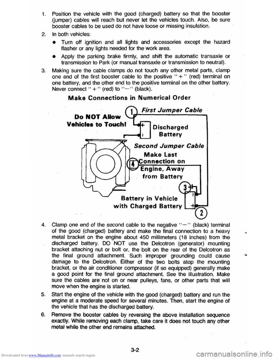
Downloaded from www.Manualslib.com manuals search engine 1. Position the vehicle with the good (charged) battery so that the booster Qumper) cables will reach but never let the vehicles touch. Also, be sure
booster cables to be used do not have loose or missing insulation.
2. tn both vehicles :
• Turn off ignition and all lights and accessories except the hazard
flasher or any lights needed for lhe work area.
• Apply the parking brake firmly, and shift the automatic transaxle or transmission to Park (or manual transaxle or transmission to neutral).
3. Making sure the cable clamps do not touch any other metal parts, clamp
one end of the first booster cable to the positive " +" (red) terminal on
one battery, and the other end to the positive terminal on the other battery .
Never connect"
+ " (red) to "- " (black).
Make Connections in Numerical Order
First Jump.r C.bl.
Do NOT Allow
Vehicle. to Touchl Discharged
Battery
S.cond Jump.r C.bl.
Make Last
onnectlon on
Engine,
Away
from Battery
Battery in Vehicle
with Charged Battery L-'= ___
o
4. Clamp one end of the second cable to the negative" -" (black) terminal
of the
good (charged) battery and make the final connection to a heavy metal bracket on the engine about 450 millimeters (18 inches) from the
discharged battery.
DO NOT use the Delcotron (generator) mounting
bracket attaching nut or bolt or, the bolt on the rear of the Delcotron as
the final ground attachment. Such improper grounding could cause
damage to the Delcotron . Either of the two bolts atop the mounting
bracket ,
or the air conditioner compressor (if so equipped) generally make a good point for the final ground attachment. See the illustration. Make
sure
the cables are not on or near pulleys , fans , or other parts that will move when the engine is started.
5. Start the engine of the vehicle with the good (charged) battery and run the
engine at a moderate speed for several minutes. Then, start the engine of
the vehicle that has the discharged battery.
6. Remove the booster cables by. raversing the above installation sequence
exactly. While removing each clamp, take care it does not touch any other metal while the other end remains attached. .
3-2
•
Page 61 of 105
Downloaded from www.Manualslib.com manuals search engine ENGINE COOLING SYSTEM OVERHEATING
If you see or hear escaping steam or have other reason to suspect there is a
serious overheat condition, stop and park the vehicle as soon as it is safe
to do so and turn off the engine immediately and get out of the vehicle.
The cooling system may overheat if the coolant level is too low, if there is a
sudden
loss of coolant (such as a worn hose splitting), or if other problems occur. It may also temporarily overheat during severe operating conditions
such as:
• climbing a long hill on a hot day,
• stopping after high-speed driving,
• idling for long periods in trallic, or
• towing a trailer.
I! the Engine Coolant Temperature light comes on (or if you have an Engine
Coolant Temperature gage and it shows an overheat condition), or you have
any reason to suspect the engine may be overheating:
• tfyour air conditioner is on, turn it off.
• If you are stopped in traffic, shift the transaxle to "N" (Neutral).
If the warning light does not go off (or engine coolant temperature does not
start to drop) within a minute
Or two:
• Pull over, stop and park the vehicle as soon as it is safe to do so.
• Let the engine run at normal idle speed for two or three minutes.
I! the warning light does not go off (or engine coolant temperature does not
start to drop),
turn off the engine and get out of the car, then proceed as
follows:
CAUTION: To help avokt being burned:
• DO NOT OPEN ntE HOOD if you see or hear steam or coolant escaping from the engine compartment. Wait until no steam or coolant can be seen or heard before opening the hood.
• DO NOT REMOVE THE RADIATOR CAP or coolant RECOVERY TANK CAP IF THE COOLANT IN THE RECOVERY TANK IS BOIUNG. Also do not remove the radiator
cap while the engine and radiator are still hot Scalding fluid and steam can be blown out under pressure if eHher cap is taken off too soon.
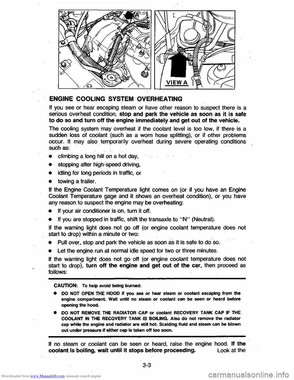
I! no steam or coolant can be seen or heard, raise the engine hood. If the
coolant is boiling, wait until it stops before proceeding. Look at the
3-3
Page 65 of 105

Downloaded from www.Manualslib.com manuals search engine 3. Install wheel and tire assembly and install hub cap by pushing or hitting
into place (the wheel can be mounted with hub cap in place). The hub cap
must be oriented by engaging the bump on the side of the hub cap
retention tab with the cutout on the side of the wheel pilot hole.
Compact Spare
The compact spare tire is designed to save space in your stowage area, and
its lighter weight makes it easier to install if a flat tire occurs. The lighter weight also helps improve fuel economy. ~--~------~~
" you have a flat tire, follow the jacking Instructions in this section, while keepingihese points in mind:
• Check the tire inflaiionpressureas soon as practical after installing the
spare (we suggest you use a 'pocket-type high'pressure inflation gage) and
adjust the pressure to 415
kilopascals (60 pounds per square inch). The
tire pressure should be checked at least monthly and kept at 415 kPa (60
psi) while the tire is stored . Also at least monthly , ·qheck that the spare lire is stowed securely ; tighten it if ~ is not.
NOTICE: Bee ... this tire is smaller than the standard tire, vehicle ground clearance is reduced. Do not take your vehicle through an automatic car wash while ~ spare I. Installed; the vehicle may catch on the equipment, possibly resulting In property damag_.
• YOU can expect a tread life up to 3,000 miles (4 800 kilometers), dependiQg on road conditions and your driving habits. The tire was designed to let you
finish an extended trip (up to 3,000 miles/4 800 kilometers) and buy a replacement tire, -if needed, at a store of your choice. However, to conserve
tire tread ~fe, return the spare to the stowage area as' soon as it is
convenient to have your standard tire repaired or replaced.
• Because the compact spare was specnically designed for your vehicle , ~ should not be used on any other vehicle.
• The compact spare tire and wheel are designed for use with each other.
The compact spare tire should not be mounted on any other type of wheel, and the compact spare wheel should not have any other type of tire
mounted on it. Also, do not try to use wheel covers or trim rings on the
CQr1l>aCt spare whe el since they will not fit. If such use is attempted,
damage to tIlese items or other vehicle components may occur.
• Do not use tire chains with your :compact spare tire. Because of the smaller tire size, a tire chain will not fit properly. This could cause damage to the
vehicle and result in loss of the chain.
3-7
Page 72 of 105
Downloaded from www.Manualslib.com manuals search engine NOTICE TO NEW CHEVROLET OWNERS REGARDING
CHEMICAL PAINT SPOTTING
Chevrolet believes that certain weather and atmospheric conditions· may create
a chemical fallout whereby certain airborne pollutants fall upon and attack
vehicle paints. Occurrences have taken place primarily in the northeastern
seaboard
area. The paint damage takes two forms: blotchy, ringlet-shaped
discoforations, and small irregular dark spots etched into the paint surface.
Paint spotting as a result of the fallout is not related to a defect. in paint materials or workmanship. For this reason, claims arising from this condition
are not considered to be warranty related. Nevertheless, because Chevrolet
shares the pride which our owners take in preserving and maintaining the
appearance of their vehicles, Chevrolet has authorized its dealers to repair, at no charge to the owner, the surfaces of new vehicles damaged by this fallout
condition within 12 months or 12,000 miles (20 000 kilometers) of purchase,
whichever comes first.
4-6