1983 FIAT UNO suspension
[x] Cancel search: suspensionPage 3 of 303
REPAIRS & OVERHAUL
Engine and Associated Systems
Engine (also see Chapter 13)Page 1•1
Cooling and heating systems (also see Chapter 13)Page2•1
Fuel system (also see Chapter 13)Page 3•1
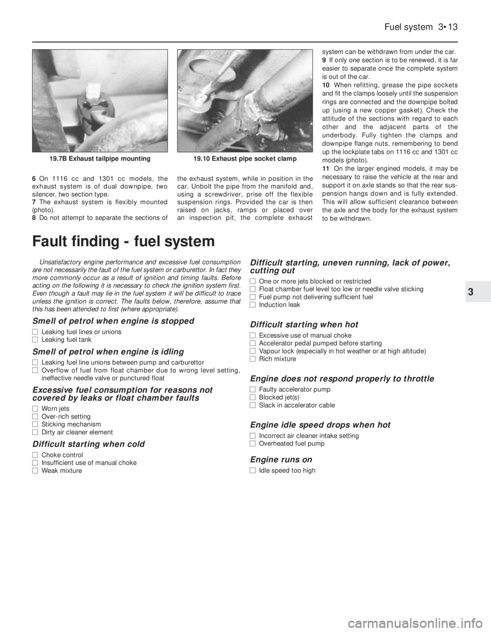
Ignition system (also see Chapter 13)Page4•1
Transmission
Clutch (also see Chapter 13)Page5•1
Transmission (also see Chapter 13)Page6•1
Driveshafts, hubs, roadwheels and tyres (also see Chapter 13)Page7•1
Brakes
Braking system(also see Chapter 13)Page 8•1
Electrical
Electrical system(also see Chapter 13)Page 9•1
Steering and suspension
SteeringPage 10•1
Suspension (also see Chapter 13)Page 11•1
Bodywork
Bodywork (also see Chapter 13)Page 12•1
Additional information
Supplement: Revisions and information on later models Page 13•1
Wiring DiagramsPage 14•1
REFERENCE
MOT Test Checks PageREF•1
Tools and Working Facilities Page REF•5
General Repair Procedures Page REF•8
Fault FindingPage REF•9
Buying Spare Parts & Vehicle Identification Numbers PageREF•12
Glossary of Technical Terms PageREF•13
IndexPage REF•17
Contents
Page 10 of 303

0•10Routine maintenance
Maintenance is essential for ensuring safety and desirable for the
purpose of getting the best in terms of performance and economy
from the car. Over the years the need for periodic lubrication has been
greatly reduced if not totally eliminated. This has unfortunately tended
to lead some owners to think that because no such action is required
the items either no longer exist or will last forever. This is certainly not
the case; it is essential to carry out regular visual examinations as
comprehensively as possible in order to spot any possible defects at
an early stage before they develop into major and expensive repairs.
For information applicable to later models, see Supplement.
Every 250 miles (400 km), weekly,
or before a long journey
m mCheck engine oil level
m mCheck brake reservoir fluid level
m mCheck tyre pressures
m mCheck operation of all lights and horn
m mTop up washer fluid reservoirs, adding a screen
wash, and check operation of washers and wipers
m mCheck coolant level
m mCheck battery electrolyte level
Every 6000 miles (10 000 km)
or six months, whichever comes first
m mRenew engine oil and filter (Chapter 1, Section 2)
m mCheck drivebelt tension (Chapter 2, Section 8)
m mCheck carburettor idle speed and mixture
adjustments (Chapter 3)
m mCheck contact points and dwell angle (mechanical
breaker distributors) (Chapter 4, Section 3)
m mCheck tyre tread wear (Chapter 7, Section 7)
m mCheck disc pads for wear (Chapter 8, Section 3)
Every 36 000 miles (60 000 km)
or three years, whichever comes first
m mRenew the timing belt - 1116 and 1299/1301 cc
(Chapter 1, Section 28)
m mCheck exhaust system for corrosion (Chapter 3,
Section 19)
m mRenew contact breaker points and adjust dwell
angle (mechanical breaker distributors) (Chapter 4,
Section 3)
m mCheck and adjust ignition timing (Chapter 4,
Section 4)
m mRenew spark plugs (Chapter 4, Section 11)
m mCheck clutch adjustment (Chapter 5, Section 2)
m mCheck transmission oil level (Chapter 6, Section 2)
m mCheck driveshaft and steering rack gaiters for splits
(Chapters 7 and 10)
m mCheck rear brake shoe linings for wear (Chapter 8,
Section 4)
m mCheck handbrake travel (Chapter 8, Section 16)
m mCheck headlamp beam alignment (Chapter 9,
Section 17)
m mCheck balljoints for wear (Chapter 10, Section 2)
m mCheck front wheel alignment (Chapter 10, Section 8)
m mCheck suspension bushes for wear (Chapter 11,
Section 2)
m mCheck seat belts for fraying (Chapter 12, Section 23)
m mLubricate controls, hinges and locks
Every 24 000 miles (40 000 km)
or two years, whichever comes first
m mRenew coolant anti-freeze mixture (Chapter 2,
Section 3)
m mRenew transmission oil (Chapter 6, Section 2)
m mRenew brake hydraulic fluid (Chapter 8, Section 12)
m mCheck for underbody corrosion and clean out door
and sill drain holes (Chapter 12, Section 2)
Every 12 000 miles (20 000 km) or
12 months, whichever comes first
m mCheck and adjust valve clearances (Chapter 1,
Sections 5 and 26)
m mRenew air cleaner element (Chapter 3, Section 2)
Page 12 of 303
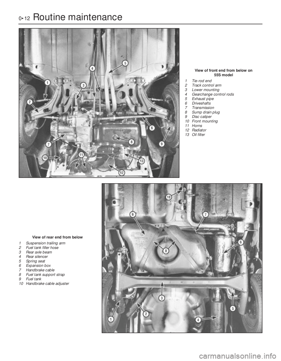
0•12Routine maintenance
View of front end from below on
55S model
1 Tie-rod end
2 Track control arm
3 Lower mounting
4 Gearchange control rods
5 Exhaust pipe
6 Driveshafts
7 Transmission
8 Sump drain plug
9 Disc caliper
10 Front mounting
11 Horns
12 Radiator
13 Oil filter
View of rear end from below
1 Suspension trailing arm
2 Fuel tank filler hose
3 Rear axle beam
4 Rear silencer
5 Spring seat
6 Expansion box
7 Handbrake cable
8 Fuel tank support strap
9 Fuel tank
10 Handbrake cable adjuster
Page 28 of 303
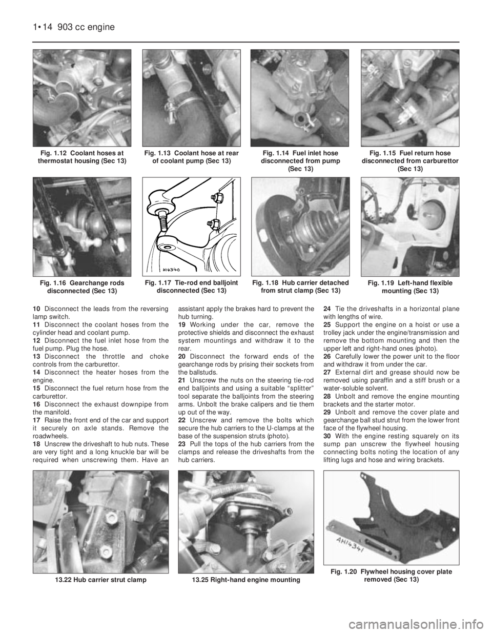
Fig. 1.20 Flywheel housing cover plate
removed (Sec 13)
Fig. 1.19 Left-hand flexible
mounting (Sec 13)
10Disconnect the leads from the reversing
lamp switch.
11Disconnect the coolant hoses from the
cylinder head and coolant pump.
12Disconnect the fuel inlet hose from the
fuel pump. Plug the hose.
13Disconnect the throttle and choke
controls from the carburettor.
14Disconnect the heater hoses from the
engine.
15Disconnect the fuel return hose from the
carburettor.
16Disconnect the exhaust downpipe from
the manifold.
17Raise the front end of the car and support
it securely on axle stands. Remove the
roadwheels.
18Unscrew the driveshaft to hub nuts. These
are very tight and a long knuckle bar will be
required when unscrewing them. Have anassistant apply the brakes hard to prevent the
hub turning.
19Working under the car, remove the
protective shields and disconnect the exhaust
system mountings and withdraw it to the
rear.
20Disconnect the forward ends of the
gearchange rods by prising their sockets from
the ballstuds.
21Unscrew the nuts on the steering tie-rod
end balljoints and using a suitable “splitter”
tool separate the balljoints from the steering
arms. Unbolt the brake calipers and tie them
up out of the way.
22Unscrew and remove the bolts which
secure the hub carriers to the U-clamps at the
base of the suspension struts (photo).
23Pull the tops of the hub carriers from the
clamps and release the driveshafts from the
hub carriers.24Tie the driveshafts in a horizontal plane
with lengths of wire.
25Support the engine on a hoist or use a
trolley jack under the engine/transmission and
remove the bottom mounting and then the
upper left and right-hand ones (photo).
26Carefully lower the power unit to the floor
and withdraw it from under the car.
27External dirt and grease should now be
removed using paraffin and a stiff brush or a
water-soluble solvent.
28Unbolt and remove the engine mounting
brackets and the starter motor.
29Unbolt and remove the cover plate and
gearchange ball stud strut from the lower front
face of the flywheel housing.
30With the engine resting squarely on its
sump pan unscrew the flywheel housing
connecting bolts noting the location of any
lifting lugs and hose and wiring brackets.
1•14 903 cc engine
13.25 Right-hand engine mounting
Fig. 1.18 Hub carrier detached
from strut clamp (Sec 13)
13.22 Hub carrier strut clamp
Fig. 1.17 Tie-rod end balljoint
disconnected (Sec 13)Fig. 1.16 Gearchange rods
disconnected (Sec 13)
Fig. 1.15 Fuel return hose
disconnected from carburettor
(Sec 13)Fig. 1.14 Fuel inlet hose
disconnected from pump
(Sec 13)Fig. 1.13 Coolant hose at rear
of coolant pump (Sec 13)Fig. 1.12 Coolant hoses at
thermostat housing (Sec 13)
Page 36 of 303

17Screw in the camshaft front bearing
lockscrew (photo).
Oil pump
18Refit the oil pump as described in Sec-
tion 10.
Timing chain and sprockets
19Fit the timing chain and sprockets as
described in Section 6. Fit the Woodruff key
to the crankshaft nose.
20Using a new gasket, fit the timing chain
cover, but leave the bolts finger tight (photo).
21Apply grease to the lips of the timing
cover oil seal and then push the crankshaft
pulley into position.
22Move the timing cover if necessary so that
the pulley hub is centralised in the oil seal and
then tighten the cover bolts.
23Screw on the crankshaft pulley nut and
tighten to the specified torque (photo).
Piston/connecting rods
24Fit these as described in Section 9.
Sump pan
25Fit the sump pan as described in Sec-
tion 8.
Cylinder head
26Stand the engine upright and fit the
cylinder head as described in Section 7.
27Insert the pushrods in their original fitted
order.
28With the rocker arm adjuster screws fully
unscrewed, locate the rocker gear and screw
on the fixing nuts.
29Adjust the valve clearances as described
in Section 5.
30Locate a new gasket in position and fit the
rocker cover (photo).
31Screw on a new oil filter (Section 2).
21 Engine- refitting ancillary
components
1Refer to Chapter 5 and refit the clutch,
making sure to centralise the driven plate.
2Fit the coolant pump as described in
Chapter 2. Fit the thermostat housing if it was
removed noting the air cleaner mounting
bracket on the housing studs.
3Fit the alternator and drivebelt as described
in Chapter 9.
4Refer to Chapter 3 and fit the exhaust
manifold and hot air collector, the carburettor
and spacer and the fuel pump.
5Fit the distributor as described in Chapter
4. Fit the oil dipstick guide tube (photos).
22 Engine/transmission-
reconnection
1
1Support the weight of the transmission and
offer it squarely to the engine. The splined
input shaft should pass easily through the hub
of the driven plate, provided the plate has
been centralised as described in Chapter 5. It
may be necessary to align the splines with the
hub grooves, in which case have an assistant
turn the crankshaft pulley nut. The alignment
dowels will make the connection stiff, so
drawing the engine and transmission together
with two connecting bolts will ease it.
2Once the engine and transmission are fully
engaged, insert and tighten all the connecting
bolts. Locate the lifting eyes.
3Bolt on the flywheel housing cover plate
and the mounting brackets.
4Bolt on the starter motor.
23 Engine/transmission-
refitting
3
1The refitting operations are reversals of
those described in Section 13.
2Observe the following special points.
3Tighten the engine mounting and front
suspension (disconnected) bolts to the
specified torque when the hoist has been
1•22 903 cc engine
21.5B Dipstick guide tube support21.5A Dipstick guide tube20.30 Rocker cover nut and thrust plate
20.23 Tightening crankshaft pulley nut20.20 Timing cover20.17 Camshaft front bearing lockscrew
Hold the crankshaft against
rotation either by jamming
the starter ring gear or by
placing a block of wood
between a crankshaft web and the
inside of the crankcase.
Page 42 of 303

from the suspension struts and then remove
the bolts which secure the hub carriers to the
U-clamps at the base of the suspension
struts.
23Pull the tops of the hub carriers down and
then outwards and push the driveshafts from
them.
24Unbolt the driveshaft inboard boot
retainers and then remove the driveshafts
from the transmission.
25Support the engine on a hoist or use a
trolley jack under the engine/transmission.
Remove the bottom mounting and then the
upper left and right-hand ones.
26Lower the power unit to the floor by
pushing it to the left-hand side to clear the
right-hand mounting bracket and then swivel
the gearbox towards the rear of the car.
Withdraw the engine/transmission from under
the car.
27External dirt and grease should now be
removed using paraffin and a stiff brush or a
water-soluble solvent.
28Unbolt and remove the engine mounting
brackets and the starter motor.
29Unbolt and remove the cover plate with
the gearchange ball stud strut from the lower
front face of the flywheel housing.
30With the engine resting squarely on its
sump pan, unscrew the flywheel housing
connecting bolts, noting the location of any
lifting lugs and hose and wiring clips.
31Support the weight of the transmission
and withdraw it in a straight line from the
engine.
36 Engine- dismantling (general)
Refer to Section 14, Part 2.
37 Engine ancillary components
- removal
Refer to Section 15, Part 2 and also remove
the intake manifold.
38 Engine-
complete dismantling
3
1Have the engine resting squarely and
supported securely on the work surface.
2Unbolt and remove the timing belt cover.
3Grip the now exposed timing belt with the
hands and loosen the camshaft sprocket.
4Release the timing belt tensioner pulley
centre bolt, then slip the belt from the pulley
and sprockets to remove it. Note which way
round the belt is fitted, usually so that the
lettering on the belt can be read from the
crankshaft pulley end of the engine.
5Remove the camshaft sprocket.6Unbolt and remove the camshaft timing belt
cover backing plate.
7Unbolt and remove the camshaft carrier
cover.
8Unbolt the camshaft carrier and lift it off
very slowly, at the same time pushing the cam
followers and their shims down with the
fingers securely onto their respective valve
springs. It is easy to remove the camshaft
carrier too quickly with some of the cam
followers stuck in it and as the carrier is lifted
away, the cam followers will fall out. If this
happens, the valve clearances will be upset as
the cam followers and shims cannot be
returned, with any certainty, to their original
positions. Keep the cam followers and shims
in their originally fitted order.
9Unscrew and remove the cylinder head
bolts and nuts, grip the manifold, rock the
head and remove the complete cylinder
head/manifold/carburettor assembly. Remove
and discard the cylinder head gasket.
10Unbolt the coolant pump from the side of
the cylinder block and remove it complete
with coolant distribution pipe. Remove the
crankcase breather.
11Remove the distributor/oil pump
driveshaft. This is simply carried out by
inserting a finger into the hole vacated by the
distributor and wedging it in the hole in the
end of the driveshaft. Lift the shaft out of
mesh with the auxiliary shaft. Where the
distributor is driven by the camshaft, a cover
plate retains the oil pump driveshaft in
position.
12Unbolt and remove the sprocket from the
end of the auxiliary shaft. The sprocket is held
to the shaft with a Woodruff key.
13Unbolt the auxiliary shaft retainer and
withdraw the shaft from the crankcase.
14Unscrew and remove the crankshaft
pulley nut. This is very tight and the flywheel
starter ring gear will have to be jammed with a
cold chisel or a suitably bent piece of steel to
prevent the crankshaft rotating.
15Withdraw the crankshaft sprocket, which
is located by the Woodruff key.
16Unbolt the front engine mounting bracket
from the cylinder block, together with the
timing belt cover screw anchor bush. Unbolt
and remove the timing belt tensioner pulley.
17Unscrew the flywheel securing bolts. Thestarter ring gear will again have to be jammed
to prevent the crankshaft rotating as the bolts
are unscrewed. Mark the flywheel position in
relation to the crankshaft mounting flange,
then remove it.
18Unbolt the front and rear crankshaft oil
seal retainer bolts from the crankcase and the
sump. Remove the oil seal retainers.
19Turn the engine on its side, extract the
remaining sump bolts and remove the sump.
If it is stuck, try tapping it gently with a
soft-faced hammer. If this fails, cut all round
the sump-to-gasket flange with a sharp knife.
Do not try prising with a large screwdriver; this
will only distort the sump mating flange.
20With the sump removed, unbolt and
remove the oil pump.
21Grip the oil pick-up pipe and twist or rock
it from its hole in the crankcase. It is an
interference fit in the hole.
22Remove the piston/connecting rods as
described in Section 32.
23Before unbolting the main bearing caps,
note that they are marked with one, two, three
or four notches. No. 5 main bearing cap is
unmarked. Note that the notches are nearer
the auxiliary shaft side.
24Unbolt and remove the main bearing
caps. If the bearing shells are to be used
again, tape them to their respective caps. The
bearing shell at the centre position is plain,
the others have a lubricating groove.
25Carefully, lift the crankshaft from the
crankcase, noting the thrust washers at No. 5
main bearing. These control the crankshaft
endfloat.
39 Cylinder head- dismantling
and decarbonising
4
1The operations are similar to those
described for the ohv engine in Section 17 in
respect of decarbonising and valve grinding.
2To remove a valve, use a valve spring
compressor to compress the first valve and
then extract the split collets (photo).
3Release the valve spring compressor.
4Withdraw the valve spring cap and the
double valve springs (photos).
5Remove the valve (photo).
1•28 1116 cc and 1301 cc engine
39.4A Valve spring cap39.2 Valve spring compressor and split
collets
Page 47 of 303
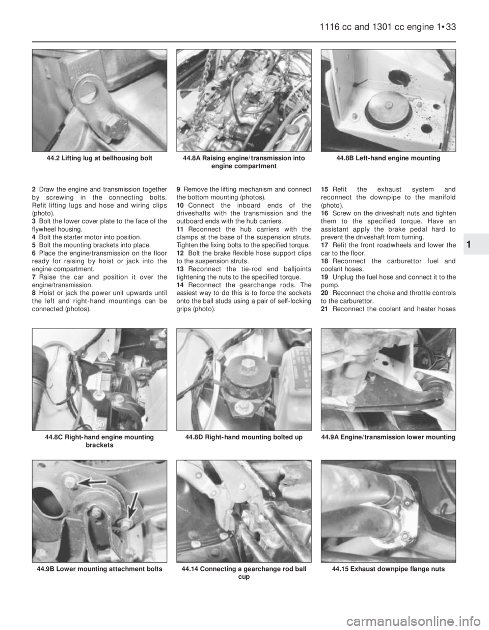
2Draw the engine and transmission together
by screwing in the connecting bolts.
Refit lifting lugs and hose and wiring clips
(photo).
3Bolt the lower cover plate to the face of the
flywheel housing.
4Bolt the starter motor into position.
5Bolt the mounting brackets into place.
6Place the engine/transmission on the floor
ready for raising by hoist or jack into the
engine compartment.
7Raise the car and position it over the
engine/transmission.
8Hoist or jack the power unit upwards until
the left and right-hand mountings can be
connected (photos).9Remove the lifting mechanism and connect
the bottom mounting (photos).
10Connect the inboard ends of the
driveshafts with the transmission and the
outboard ends with the hub carriers.
11Reconnect the hub carriers with the
clamps at the base of the suspension struts.
Tighten the fixing bolts to the specified torque.
12Bolt the brake flexible hose support clips
to the suspension struts.
13Reconnect the tie-rod end balljoints
tightening the nuts to the specified torque.
14Reconnect the gearchange rods. The
easiest way to do this is to force the sockets
onto the ball studs using a pair of self-locking
grips (photo).15Refit the exhaust system and
reconnect the downpipe to the manifold
(photo).
16Screw on the driveshaft nuts and tighten
them to the specified torque. Have an
assistant apply the brake pedal hard to
prevent the driveshaft from turning.
17Refit the front roadwheels and lower the
car to the floor.
18Reconnect the carburettor fuel and
coolant hoses.
19Unplug the fuel hose and connect it to the
pump.
20Reconnect the choke and throttle controls
to the carburettor.
21Reconnect the coolant and heater hoses
1116 cc and 1301 cc engine 1•33
44.8B Left-hand engine mounting44.8A Raising engine/transmission into
engine compartment44.2 Lifting lug at bellhousing bolt
44.15 Exhaust downpipe flange nuts44.14 Connecting a gearchange rod ball
cup44.9B Lower mounting attachment bolts
44.9A Engine/transmission lower mounting44.8D Right-hand mounting bolted up44.8C Right-hand engine mounting
brackets
1
Page 71 of 303
6On 1116 cc and 1301 cc models, the
exhaust system is of dual downpipe, two
silencer, two section type.
7The exhaust system is flexibly mounted
(photo).
8Do not attempt to separate the sections ofthe exhaust system, while in position in the
car. Unbolt the pipe from the manifold and,
using a screwdriver, prise off the flexible
suspension rings. Provided the car is then
raised on jacks, ramps or placed over
an inspection pit, the complete exhaust system can be withdrawn from under the car.
9If only one section is to be renewed, it is far
easier to separate once the complete system
is out of the car.
10When refitting, grease the pipe sockets
and fit the clamps loosely until the suspension
rings are connected and the downpipe bolted
up (using a new copper gasket). Check the
attitude of the sections with regard to each
other and the adjacent parts of the
underbody. Fully tighten the clamps and
downpipe flange nuts, remembering to bend
up the lockplate tabs on 1116 cc and 1301 cc
models (photo).
11On the larger engined models, it may be
necessary to raise the vehicle at the rear and
support it on axle stands so that the rear sus-
pension hangs down and is fully extended.
This will allow sufficient clearance between
the axle and the body for the exhaust system
to be withdrawn.
Fuel system 3•13
3
19.10 Exhaust pipe socket clamp19.7B Exhaust tailpipe mounting
Fault finding - fuel system
Unsatisfactory engine performance and excessive fuel consumption
are not necessarily the fault of the fuel system or carburettor. In fact they
more commonly occur as a result of ignition and timing faults. Before
acting on the following it is necessary to check the ignition system first.
Even though a fault may lie in the fuel system it will be difficult to trace
unless the ignition is correct. The faults below, therefore, assume that
this has been attended to first (where appropriate).
Smell of petrol when engine is stopped
m mLeaking fuel lines or unions
m mLeaking fuel tank
Smell of petrol when engine is idling
m
mLeaking fuel line unions between pump and carburettor
m mOverflow of fuel from float chamber due to wrong level setting,
ineffective needle valve or punctured float
Excessive fuel consumption for reasons not
covered by leaks or float chamber faults
m mWorn jets
m mOver-rich setting
m mSticking mechanism
m mDirty air cleaner element
Difficult starting when cold
m
mChoke control
m mInsufficient use of manual choke
m mWeak mixture
Difficult starting, uneven running, lack of power,
cutting out
m mOne or more jets blocked or restricted
m mFloat chamber fuel level too low or needle valve sticking
m mFuel pump not delivering sufficient fuel
m mInduction leak
Difficult starting when hot
m
mExcessive use of manual choke
m mAccelerator pedal pumped before starting
m mVapour lock (especially in hot weather or at high altitude)
m mRich mixture
Engine does not respond properly to throttle
m
mFaulty accelerator pump
m mBlocked jet(s)
m mSlack in accelerator cable
Engine idle speed drops when hot
m
mIncorrect air cleaner intake setting
m mOverheated fuel pump
Engine runs on
m
mIdle speed too high