1983 FIAT UNO oil temperature
[x] Cancel search: oil temperaturePage 78 of 303

important that the following precautions are
observed.
3Never start the engine if the battery leads
are loose.
4Do not stop the engine by pulling off a
battery lead.
5Remove the control unit if ambient
temperature (paint drying oven) is above 80ºC
(176ºF).
6Never connect or disconnect the multi-plug
at the control unit unless the ignition is
switched off.
7Disconnect the battery negative lead before
carrying out electric body welding.10 Digiplex (electronic) ignition
- checks and adjustments
3
1Without special equipment, any work on the
system components should be restricted to
the following.
Engine speed sensor
2The gap between the sensor and the teeth
of the flywheel should be between 0.25 and
1.3 mm (0.0099 to 0.0512 in). Any
deviation will be due to mechanical damage to
the sensor, no adjustment being possible.
TDC sensor
3The gap between the sensor and one of the
TDC reference marks on the crankshaft pulley
should be between 0.4 and 1.0 mm (0.016 to
0.039 in).
4Any deviation will be due to the sensor
plate becoming loose. To reposition it will
necessitate setting No. 1 piston at TDC which
can only be carried out accurately by your
dealer using special tools.
Supply circuit and continuity of
coil primary winding
5Connect a test lamp between contacts 11
and 9 of the multi-plug having first pulled it
from the control unit.
6Switch on the ignition, the test lamp should
come on. If it does not, either the connection
at the positive pole of the control unit or the
coil primary winding is open.
Control unit earth
7Connect a test lamp between contacts 8
and 9 of the multi-plug having first pulled it
from the control unit. Switch on the ignition,
the test lamp should come on. If it does not,
improve the earth connection.
11 Spark plugs
1
1The correct functioning of the spark plugs is
vital for the correct running and efficiency of the
engine. It is essential that the plugs fitted are
appropriate for the engine, and the suitable type
is specified at the beginning of this chapter. If
Ignition system 4•7
Fig. 4.9 Digiplex control unit (Sec 9)
1 Vacuum hose connector
2 Multi-plug socket
1 Control unit
2 Distributor
3 Ignition coil4 TDC sensor
5 Wiring connector plug6 Engine speed sensor
7 Wiring connector plug
Fig. 4.8 Location of Digiplex ignition system components (Sec 9)
Fig. 4.13 Test lamp connected between
terminals 8 and 9 of control unit multi-plug
(Sec 10)Fig. 4.12 Test lamp connected between
terminals 11 and 9 of control unit
multi-plug (Sec 10)
Fig. 4.11 TDC sensor gap (Sec 10)
Fig. 4.10 Engine speed sensor gap
(Sec 10)
4
Page 101 of 303

3The centralised door locking system can
operate independently of the key.
4To gain access to the lock solenoid and
linkage, remove the front door trim panel as
described in Chapter 12.
5Disconnect the battery negative lead.
6Disconnect the electrical wiring plugs from
the solenoid within the door cavity.
7Disconnect the solenoid from the lock lever
by removing the clip.
8Unscrew the two bolts which secure the
solenoid to the door and remove it.
9Renew the solenoid or switch as necessary.
10Refitting is a reversal of removal.
11Refer to Section 10 for details of system
fuses and relays.
33 Economy gauge
(Econometer)
2
1This device is fitted to ES (energy saving)
models and indicates to the driver the fuel
consumption (in litres per 100 km) coupled
with a needle which moves over coloured
sections of a dial to make the driver aware
that his method of driving is either conducive
to high or low fuel consumption. Refer to
Chapter 3, Section 16.
2The device is essentially a vacuum gauge
which also incorporates a warning lamp to
indicate to the driver when a change of gear is
required.
3A fuel cut-out valve (see Chapter 3, Sec-
tion 11) is used in conjunction with the
economy gauge so that when the accelerator
pedal is released during a pre-determined
engine speed range, fuel supply to the engine
is stopped, but resumes when the engine
speed falls below the specified range.
LED (light emitter diode)
4The gearchange indicator will only light up
at engine speeds in excess of 2000 rev/min
for vacuum pressures up to 600 mm Hg in 1st,
2nd and 3rd speed gears and for vacuum
pressures up to 676 mm Hg in 4th speedgear. The light will not come on if 5th speed
gear is engaged or if the coolant temperature
is below 55ºC.
5There is a two second delay in the light
coming on to prevent it operating during rapid
acceleration in a low gear.
6If the LED light comes on during
deceleration it should be ignored.
Fault finding
7A faulty economy gauge should be checked
in the following way.
8Refer to Section 21 and remove the
instrument panel.
9Disconnect the economy gauge L
connector and then connect a test lamp
between the BN cable contact and earth. If
the lamp comes on then the gauge supply
circuit is not open. If the lamp does not come
on, check all connections in the supply cable
which comes from the interconnecting unit of
the electrical system, also Fuse No 12.
10Now connect a voltmeter between the
white cable and earth. Check the voltage with
the engine not running, but the ignition
switched on. It should be between 0.7 and
0.9 volt. If the reading varies considerably
from that specified, check the connections
between the economy gauge and the fuel
cut-out device control unit. If the fault cannot
be rectified, renew the ignition control unit
(Digiplex system, see Chapter 4).
11Now check the closed throttle valve plate
switch by connecting a voltmeter between the
brown and BN cables of the L connector. With
the valve plate open, there should be no
reading, but with it open, voltage should be
indicated.
12Failure to conform as described will be
due to a faulty earth in the switch or a faulty
fuel cut-out device control unit.
13A further test of the throttle valve plate
switch may be carried out by disconnecting
the multi-plug from the fuel cut-out device
control unit.
14Connect a test lamp to contact 4 (positive
battery terminal). The lamp should come on,
when the engine is idling or the accelerator
released. If it does not, renew the throttle
valve plate switch.15Connect a tachometer to the brown/white
cable contact in the L connector and record
the engine speed with the engine running. If
no reading is obtained, renew the Digiplex
ignition control unit which must be faulty.
34 Check control (warning
module) system
2
1This is fitted into the instrument panel of
certain models to provide a means of
checking the operation of many electrical
circuits and other systems in the interest of
safety. Sensors are used where appropriate.
2The following components are not
monitored by the system, but have separate
warning lamps:
Handbrake “on”
Choke in use
Low engine oil pressure
Battery charge indicator
3The multi-functional electronic device
automatically checks the following functions
whether the engine is running or not:
Coolant level
Disc pad wear
Door closure
Engine oil level
Front parking lamps
Rear foglamps
Stop lamps
4The check information is stored by the
system monitor until the engine is started
when the display panel then indicates the
situation by means of the LEDs (light emitter
diodes) and the general lamp.
5If all functions are in order, the green panel
lamp will come on when the ignition key is
turned and will go out after two to three
seconds.
6If some functions are not in order, then the
red panel lamp will come on also the
appropriate LED.
Sensors - checking
7If a fault signal occurs which is
subsequently found to be incorrect, first
check the wiring connections between the
9•12 Electrical system
Fig. 9.15 Check system control panel (Sec 34)
A Parking lamps
B Coolant levelC Engine oil level
D Door closureE Brake fluid level
F Disc pad wearFig. 9.14 Location of control units (Sec 33)
A Digiplex ignition system control unit
B Fuel cut-out valve control unit
Page 127 of 303

Cooling system................................................................................. 8
Part A: 999 cc engine
Description
Maintenance
Thermostat - removal and refitting
Coolant pump - removal and refitting
Part B: 1301 cc Turbo ie engine
Description
Part C: 1372 cc ie and 1372 cc Turbo ie engines
Description
Maintenance
Cooling system - draining, flushing and refilling
Radiator (and cooling fan) - removal and refitting
Thermostat - removal and refitting
Coolant pump - removal and refitting
Coolant pump/alternator drivebelt - checking, renewal and
tensioning
Part D: Heater unit later models
Heater unit - removal and refitting
Heater unit - dismantling and reassembly
Fuel and exhaust systems............................................................... 9
Part A: General
Unleaded fuel
Air cleaner modified types
Fuel pump (999 cc engine) - description, removal and
refitting
Fuel tank (999 cc engine)
Part B: Carburettor models
Carburettor (Weber 32 TLF) - description
Carburettor (Weber 32 TLF) - idle speed and mixture
Carburettor (Weber 32 TLF) - removal and refitting
Carburettor (Weber 32 TLF) - overhaul
Carburettor (Weber 30/32 DMTE) - general
Carburettor (Weber 30/32 DMTE) - overhaul
Carburettor (Weber 32 ICEV 61/250 and DMTE 30/32,
DMTE 30/150) - general
Carburettor (Solex C 30/32-CIC 8) - description
Part C: Bosch LE-2 Jetronic fuel injection system
Description
Maintenance
Fuel filter - renewal
Air cleaner element - renewal
Idle speed and mixture - adjustment
Fuel injection system - electrical tests
Fuel injection system - mechanical tests
Fuel injection system components - removal and
refitting
Throttle control linkage - general
Fuel tank - general
Part D: Bosch Mono-Jetronic fuel injection system
Description
Maintenance
Fuel filter - renewal
Air cleaner element - renewal
Idle speed and mixture adjustment
Accelerator control system - check and adjustment
Fuel system - depressurisation
Fuel pump and supply - system checks
Fuel pump - removal and refitting
Injector unit - removal and refitting
Intake air temperature sensor - removal and refitting
Fuel injector - removal and refitting
Electronic control unit (ECU) - removal and refitting
Inlet manifold - removal and refitting
Exhaust manifold - removal and refitting
Catalytic converter - general information
Fuel evaporation control system - generalPart E: Bosch L3.1/2 Jetronic fuel injection systems
Description
Fuel system - depressurisation
Maintenance
Fuel filter - renewal
Air cleaner element - renewal
Checks and adjustments
Injection system components - removal and refitting
Part G: Turbocharger system
Description
Precautions
Turbocharger (1301 cc ie engine) - removal and refitting
Turbocharger (1372 cc ie engine) - removal and refitting
Intercooler - removal and refitting
Injector cooling fan - removal and refitting
Fault finding - fuel injection system
Fault finding - turbocharger system
Ignition system................................................................................. 10
General
Ignition timing (all later models)
Breakerless ignition system - description
Distributor (breakerless type) - removal and refitting
Distributor (breakerless type) - overhaul
Breakerless ignition system components - testing
Microplex ignition system - description
Distributor (Microplex) - removal and refitting
Microplex ignition system components - testing
Digiplex 2 ignition system - description
Distributor (Digiplex 2) - removal and refitting
Spark plugs and HT leads - general
Fault finding - Microplex ignition system
Clutch................................................................................................ 11
Clutch pedal adjustment (cable clutch)
Hydraulic clutch - description
Maintenance (hydraulic clutch)
Clutch master cylinder - removal, overhaul and
refitting
Clutch operating cylinder - removal, overhaul and
refitting
Clutch hydraulic system - bleeding
Transmission.................................................................................... 12
Part A: 1301 cc Turbo ie engine
Description
Gearchange linkage - removal and refitting
Gearchange linkage (Antiskid models) - general
Final drive output shafts - description and oil seal
renewal
Part B: 1372 cc ie and 1372 cc Turbo ie engines
Description
Maintenance
Oil level - checking
Oil - renewal
Gearlever and linkages - general
Transmission - removal and refitting
Part C: 999 and 1108 cc with C514 type transmission
Description
Maintenance
Driveshafts........................................................................................ 13
Inboard joint boots (non-Turbo models, September 1987 on) -
modification
Intermediate driveshaft (Turbo ie models)
Inboard CV joints (Turbo ie models - overhaul
Right-hand driveshaft damper weight (1108 and 1372 cc
models) - removal and refitting
13•2 Supplement: Revisions and information on later models
Page 133 of 303
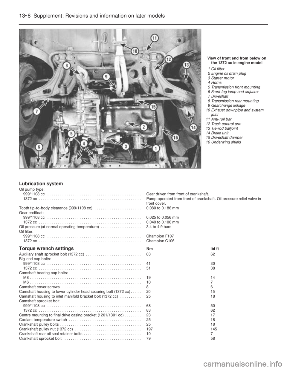
Lubrication system
Oil pump type:
999/1108 cc . . . . . . . . . . . . . . . . . . . . . . . . . . . . . . . . . . . . . . . . . . . . Gear driven from front of crankshaft.
1372 cc . . . . . . . . . . . . . . . . . . . . . . . . . . . . . . . . . . . . . . . . . . . . . . . . Pump operated from front of crankshaft. Oil pressure relief valve in
front cover.
Tooth tip-to-body clearance (999/1108 cc) . . . . . . . . . . . . . . . . . . . . . . 0.080 to 0.186 mm
Gear endfloat:
999/1108 cc . . . . . . . . . . . . . . . . . . . . . . . . . . . . . . . . . . . . . . . . . . . . 0.025 to 0.056 mm
1372 cc . . . . . . . . . . . . . . . . . . . . . . . . . . . . . . . . . . . . . . . . . . . . . . . . 0.040 to 0.106 mm
Oil pressure (at normal operating temperature) . . . . . . . . . . . . . . . . . . . 3.4 to 4.9 bars
Oil filter:
999/1108 cc . . . . . . . . . . . . . . . . . . . . . . . . . . . . . . . . . . . . . . . . . . . . Champion F107
1372 cc . . . . . . . . . . . . . . . . . . . . . . . . . . . . . . . . . . . . . . . . . . . . . . . . Champion C106
Torque wrench settingsNm lbf ft
Auxiliary shaft sprocket bolt (1372 cc) . . . . . . . . . . . . . . . . . . . . . . . . . . 83 62
Big-end cap bolts:
999/1108 cc . . . . . . . . . . . . . . . . . . . . . . . . . . . . . . . . . . . . . . . . . . . . 41 30
1372 cc . . . . . . . . . . . . . . . . . . . . . . . . . . . . . . . . . . . . . . . . . . . . . . . . 51 38
Camshaft bearing cap bolts:
M8 . . . . . . . . . . . . . . . . . . . . . . . . . . . . . . . . . . . . . . . . . . . . . . . . . . . . 19 14
M6 . . . . . . . . . . . . . . . . . . . . . . . . . . . . . . . . . . . . . . . . . . . . . . . . . . . . 10 7
Camshaft cover screws . . . . . . . . . . . . . . . . . . . . . . . . . . . . . . . . . . . . . 8 6
Camshaft housing to lower cylinder head securing bolt (1372 cc) . . . . . 20 15
Camshaft housing to inlet manifold bracket bolt (1372 cc) . . . . . . . . . . 25 18
Camshaft sprocket bolt
999/1108 cc . . . . . . . . . . . . . . . . . . . . . . . . . . . . . . . . . . . . . . . . . . . . 68 50
1372 cc . . . . . . . . . . . . . . . . . . . . . . . . . . . . . . . . . . . . . . . . . . . . . . . . 83 62
Centre mounting to final drive casing bracket (1201/1301 cc) . . . . . . . . 23 17
Coolant temperature switch . . . . . . . . . . . . . . . . . . . . . . . . . . . . . . . . . . 25 18
Crankshaft pulley bolts . . . . . . . . . . . . . . . . . . . . . . . . . . . . . . . . . . . . . . 25 18
Crankshaft pulley nut (1372 cc) . . . . . . . . . . . . . . . . . . . . . . . . . . . . . . . 197 145
Crankshaft rear oil seal retainer bolts . . . . . . . . . . . . . . . . . . . . . . . . . . . 10 7
Crankshaft sprocket bolt . . . . . . . . . . . . . . . . . . . . . . . . . . . . . . . . . . . . 79 58
13•8 Supplement: Revisions and information on later models
View of front end from below on
the 1372 cc ie engine model
1 Oil filter
2 Engine oil drain plug
3 Starter motor
4 Horns
5 Transmission front mounting
6 Front fog lamp and adjuster
7 Driveshaft
8 Transmission rear mounting
9 Gearchange linkage
10 Exhaust downpipe and system
joint
11 Anti-roll bar
12 Track control arm
13 Tie-rod balljoint
14 Brake unit
15 Driveshaft damper
16 Underwing shield
Page 134 of 303
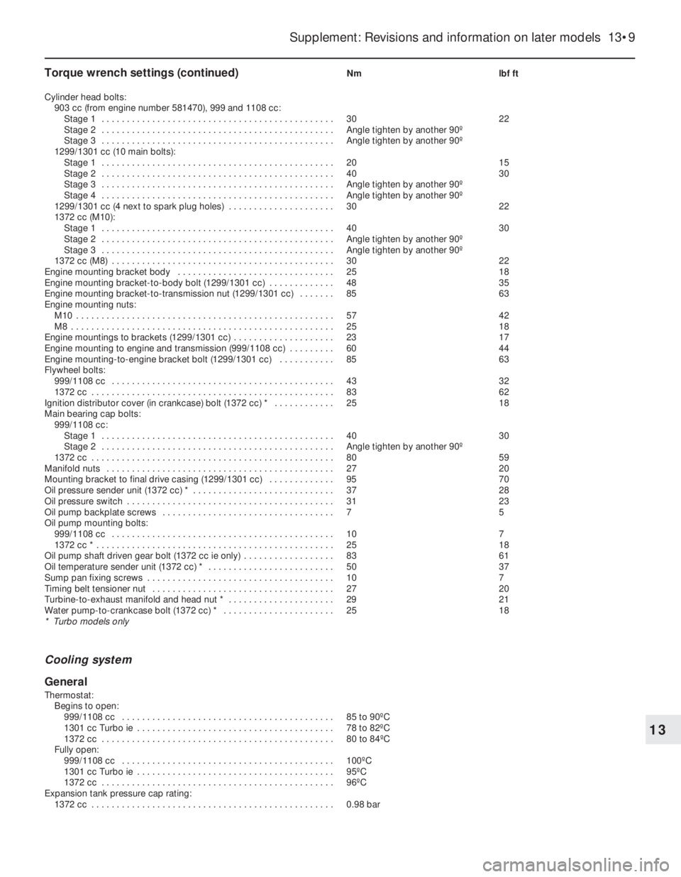
Torque wrench settings (continued)Nm lbf ft
Cylinder head bolts:
903 cc (from engine number 581470), 999 and 1108 cc:
Stage 1 . . . . . . . . . . . . . . . . . . . . . . . . . . . . . . . . . . . . . . . . . . . . . . 30 22
Stage 2 . . . . . . . . . . . . . . . . . . . . . . . . . . . . . . . . . . . . . . . . . . . . . . Angle tighten by another 90º
Stage 3 . . . . . . . . . . . . . . . . . . . . . . . . . . . . . . . . . . . . . . . . . . . . . . Angle tighten by another 90º
1299/1301 cc (10 main bolts):
Stage 1 . . . . . . . . . . . . . . . . . . . . . . . . . . . . . . . . . . . . . . . . . . . . . . 20 15
Stage 2 . . . . . . . . . . . . . . . . . . . . . . . . . . . . . . . . . . . . . . . . . . . . . . 40 30
Stage 3 . . . . . . . . . . . . . . . . . . . . . . . . . . . . . . . . . . . . . . . . . . . . . . Angle tighten by another 90º
Stage 4 . . . . . . . . . . . . . . . . . . . . . . . . . . . . . . . . . . . . . . . . . . . . . . Angle tighten by another 90º
1299/1301 cc (4 next to spark plug holes) . . . . . . . . . . . . . . . . . . . . . 30 22
1372 cc (M10):
Stage 1 . . . . . . . . . . . . . . . . . . . . . . . . . . . . . . . . . . . . . . . . . . . . . . 40 30
Stage 2 . . . . . . . . . . . . . . . . . . . . . . . . . . . . . . . . . . . . . . . . . . . . . . Angle tighten by another 90º
Stage 3 . . . . . . . . . . . . . . . . . . . . . . . . . . . . . . . . . . . . . . . . . . . . . . Angle tighten by another 90º
1372 cc (M8) . . . . . . . . . . . . . . . . . . . . . . . . . . . . . . . . . . . . . . . . . . . . 30 22
Engine mounting bracket body . . . . . . . . . . . . . . . . . . . . . . . . . . . . . . . 25 18
Engine mounting bracket-to-body bolt (1299/1301 cc) . . . . . . . . . . . . . 48 35
Engine mounting bracket-to-transmission nut (1299/1301 cc) . . . . . . . 85 63
Engine mounting nuts:
M10 . . . . . . . . . . . . . . . . . . . . . . . . . . . . . . . . . . . . . . . . . . . . . . . . . . . 57 42
M8 . . . . . . . . . . . . . . . . . . . . . . . . . . . . . . . . . . . . . . . . . . . . . . . . . . . . 25 18
Engine mountings to brackets (1299/1301 cc) . . . . . . . . . . . . . . . . . . . . 23 17
Engine mounting to engine and transmission (999/1108 cc) . . . . . . . . . 60 44
Engine mounting-to-engine bracket bolt (1299/1301 cc) . . . . . . . . . . . 85 63
Flywheel bolts:
999/1108 cc . . . . . . . . . . . . . . . . . . . . . . . . . . . . . . . . . . . . . . . . . . . . 43 32
1372 cc . . . . . . . . . . . . . . . . . . . . . . . . . . . . . . . . . . . . . . . . . . . . . . . . 83 62
Ignition distributor cover (in crankcase) bolt (1372 cc) * . . . . . . . . . . . . 25 18
Main bearing cap bolts:
999/1108 cc:
Stage 1 . . . . . . . . . . . . . . . . . . . . . . . . . . . . . . . . . . . . . . . . . . . . . . 40 30
Stage 2 . . . . . . . . . . . . . . . . . . . . . . . . . . . . . . . . . . . . . . . . . . . . . . Angle tighten by another 90º
1372 cc . . . . . . . . . . . . . . . . . . . . . . . . . . . . . . . . . . . . . . . . . . . . . . . . 80 59
Manifold nuts . . . . . . . . . . . . . . . . . . . . . . . . . . . . . . . . . . . . . . . . . . . . . 27 20
Mounting bracket to final drive casing (1299/1301 cc) . . . . . . . . . . . . . 95 70
Oil pressure sender unit (1372 cc) * . . . . . . . . . . . . . . . . . . . . . . . . . . . . 37 28
Oil pressure switch . . . . . . . . . . . . . . . . . . . . . . . . . . . . . . . . . . . . . . . . . 31 23
Oil pump backplate screws . . . . . . . . . . . . . . . . . . . . . . . . . . . . . . . . . . 7 5
Oil pump mounting bolts:
999/1108 cc . . . . . . . . . . . . . . . . . . . . . . . . . . . . . . . . . . . . . . . . . . . . 10 7
1372 cc * . . . . . . . . . . . . . . . . . . . . . . . . . . . . . . . . . . . . . . . . . . . . . . . 25 18
Oil pump shaft driven gear bolt (1372 cc ie only) . . . . . . . . . . . . . . . . . . 83 61
Oil temperature sender unit (1372 cc) * . . . . . . . . . . . . . . . . . . . . . . . . . 50 37
Sump pan fixing screws . . . . . . . . . . . . . . . . . . . . . . . . . . . . . . . . . . . . . 10 7
Timing belt tensioner nut . . . . . . . . . . . . . . . . . . . . . . . . . . . . . . . . . . . . 27 20
Turbine-to-exhaust manifold and head nut * . . . . . . . . . . . . . . . . . . . . . 29 21
Water pump-to-crankcase bolt (1372 cc) * . . . . . . . . . . . . . . . . . . . . . . 25 18
* Turbo models only
Cooling system
General
Thermostat:
Begins to open:
999/1108 cc . . . . . . . . . . . . . . . . . . . . . . . . . . . . . . . . . . . . . . . . . . 85 to 90ºC
1301 cc Turbo ie . . . . . . . . . . . . . . . . . . . . . . . . . . . . . . . . . . . . . . . 78 to 82ºC
1372 cc . . . . . . . . . . . . . . . . . . . . . . . . . . . . . . . . . . . . . . . . . . . . . . 80 to 84ºC
Fully open:
999/1108 cc . . . . . . . . . . . . . . . . . . . . . . . . . . . . . . . . . . . . . . . . . . 100ºC
1301 cc Turbo ie . . . . . . . . . . . . . . . . . . . . . . . . . . . . . . . . . . . . . . . 95ºC
1372 cc . . . . . . . . . . . . . . . . . . . . . . . . . . . . . . . . . . . . . . . . . . . . . . 96ºC
Expansion tank pressure cap rating:
1372 cc . . . . . . . . . . . . . . . . . . . . . . . . . . . . . . . . . . . . . . . . . . . . . . . . 0.98 bar
Supplement: Revisions and information on later models 13•9
13
Page 148 of 303
depressurize the fuel system, before
disconnecting the fuel pipes and removing the
throttle body, as described in Section 9D.
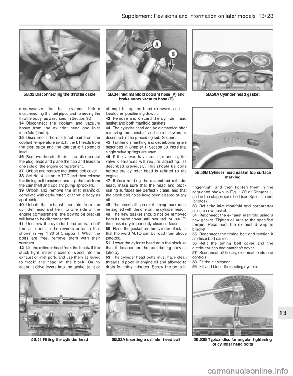
34Disconnect the coolant and vacuum
hoses from the cylinder head and inlet
manifold (photo).
35Disconnect the electrical lead from the
coolant temperature switch, the LT leads from
the distributor and the idle cut-off solenoid
lead.
36Remove the distributor cap, disconnect
the plug leads and place the cap and leads to
one side of the engine compartment.
37Unbolt and remove the timing belt cover.
38Set No. 4 piston to TDC and then release
the timing belt tensioner and slip the belt from
the camshaft and coolant pump sprockets.
39Unbolt and remove the inlet manifold,
complete with carburettor, or throttle body as
applicable.
40Unbolt the exhaust manifold from the
cylinder head and tie it to one side of the
engine compartment; the downpipe bracket
will have to be disconnected.
41Unscrew the cylinder head bolts, a half
turn at a time in the reverse order to that
shown in Fig. 1.30 of Chapter 1. When the
bolts are free, remove them with their
washers.
42Lift the cylinder head from the block. If it is
stuck tight, insert pieces of wood into the
exhaust or inlet ports and use them as levers
to “rock” the head off the block. On no
account drive levers into the gasket joint orattempt to tap the head sideways as it is
located on positioning dowels.
43Remove and discard the cylinder head
gasket and both manifold gaskets.
44The cylinder head can be dismantled after
removing the camshaft and cam followers as
described in the preceding sub-Section.
45Further dismantling and decarbonising are
described in Chapter 1, Section 39. Note that
single valve springs are used.
46If the valves have been ground in, the
valve clearances will require adjusting, as
described previously. This should be done
before the cylinder head is refitted to the
engine.
47Before refitting the assembled cylinder
head, make sure that the head and block
mating surfaces are perfectly clean, and that
the block bolt holes have been cleared of any
oil.
48The camshaft sprocket timing mark must
be aligned with the one on the cylinder head.
49The new gasket should not be removed
from its nylon cover until required for use. Fit
the gasket dry to perfectly clean surfaces.
50Place the gasket on the cylinder block so
that the word ALTO can be read from above
(photos).
51Lower the cylinder head onto the block so
that it locates on the positioning dowels
(photo).
52The cylinder head bolts must have clean
threads, dipped in engine oil and allowed to
drain for thirty minutes. Screw the bolts infinger-tight and then tighten them in the
sequence shown in Fig. 1.30 of Chapter 1,
and in the stages specified (see Specification)
(photos).
53Refit the inlet manifold and carburettor
using a new gasket.
54Reconnect the exhaust manifold using a
new gasket. Tighten all nuts to the specified
torque. Reconnect the exhaust downpipe
bracket.
55Reconnect the timing belt and tension it
as described earlier.
56Refit the timing belt cover and the
distributor cap and camshaft cover.
57Reconnect all hoses, electrical leads and
controls.
58Fit the air cleaner.
59Fill and bleed the cooling system.
Supplement: Revisions and information on later models 13•23
5B.50A Cylinder head gasket5B.34 Inlet manifold coolant hose (A) and
brake servo vacuum hose (B)5B.32 Disconnecting the throttle cable
5B.52B Typical disc for angular tightening
of cylinder head bolts
5B.50B Cylinder head gasket top surface
marking
5B.52A Inserting a cylinder head bolt5B.51 Fitting the cylinder head
13
Page 152 of 303
8Disconnect the heater hose from the inlet
manifold.
9On fuel injection models, depressurize the
fuel system (refer to Section 9D). Disconnect
the fuel inlet and return hoses from the fuel
pump (photo) or throttle body, as applicable.
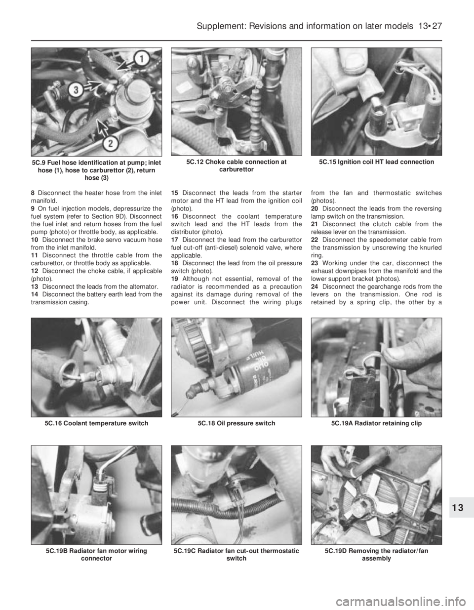
10Disconnect the brake servo vacuum hose
from the inlet manifold.
11Disconnect the throttle cable from the
carburettor, or throttle body as applicable.
12Disconnect the choke cable, if applicable
(photo).
13Disconnect the leads from the alternator.
14Disconnect the battery earth lead from the
transmission casing.15Disconnect the leads from the starter
motor and the HT lead from the ignition coil
(photo).
16Disconnect the coolant temperature
switch lead and the HT leads from the
distributor (photo).
17Disconnect the lead from the carburettor
fuel cut-off (anti-diesel) solenoid valve, where
applicable.
18Disconnect the lead from the oil pressure
switch (photo).
19Although not essential, removal of the
radiator is recommended as a precaution
against its damage during removal of the
power unit. Disconnect the wiring plugs from the fan and thermostatic switches
(photos).
20Disconnect the leads from the reversing
lamp switch on the transmission.
21Disconnect the clutch cable from the
release lever on the transmission.
22Disconnect the speedometer cable from
the transmission by unscrewing the knurled
ring.
23Working under the car, disconnect the
exhaust downpipes from the manifold and the
lower support bracket (photos).
24Disconnect the gearchange rods from the
levers on the transmission. One rod is
retained by a spring clip, the other by a
Supplement: Revisions and information on later models 13•27
5C.15 Ignition coil HT lead connection5C.12 Choke cable connection at
carburettor5C.9 Fuel hose identification at pump; inlet
hose (1), hose to carburettor (2), return
hose (3)
5C.19D Removing the radiator/fan
assembly5C.19C Radiator fan cut-out thermostatic
switch5C.19B Radiator fan motor wiring
connector
5C.19A Radiator retaining clip5C.18 Oil pressure switch5C.16 Coolant temperature switch
13
Page 158 of 303

32Fit the hot air collector plate for the air
cleaner (photo).
33Refer to Section 10 and fit the distributor.
34Bolt on the timing belt cover.
35Fit the camshaft cover, using a new
gasket unless the original one is in perfect
condition.
Engine/transmission -
reconnection and refitting#
36Locate the engine in an upright position
on wooden blocks to allow for the greater
depth of the transmission flywheel housing
when it is joined to the engine.
37Make sure that the clutch driven plate has
been centralised, offer the transmission to the
engine and locate the flywheel housing on the
single stud and dowels.
38Tighten the connecting bolts to specifiedtorque, having located the lifting eye (photo).
39Bolt on the starter motor.
40Refit the cover plate to the flywheel
housing, but do not insert the lower bolts at
this stage as they retain the support bracket
for the gearchange rod.
41The engine and transmission are now
ready for refitting. The operations are a direct
reversal of the operations described earlier,
but observe the following points.
42Have the engine/transmission perfectly
horizontal and suspended on the hoist.
43Lower it into position very slowly until it is
possible to engage the driveshaft inboard
joints with the transmission.
44Continue lowering until the driveshafts
can be fully engaged and the mountings
reconnected. Remove the hoist.
45Tighten all nuts and bolts to the specifiedtorque. Note the method shown for
connecting the gearchange rod ball socket
using pliers (photo).
46Refill the engine with oil and coolant and
replenish the transmission oil.
Initial start-up after major
overhaul
47Refer to Chapter 1, Section 45.
6 Engine-
1301 cc Turbo ie
PART A: GENERAL
Description
1This engine is similar in design to the
1301 cc engine described in Chapter 1, but
the fuel and ignition systems are different, and
a turbocharger, oil cooler and intercooler are
fitted.
2Many dimensions and tolerances have
been altered for this engine, and reference
should be made to the Specifications at the
beginning of this Supplement.
3Operations which differ from those
described in Chapter 1 are given in the
following sub-Sections.
Lubrication system - description
4The lubrication system differs from the
non-Turbo 1301 cc engine in the following
respects.
5An oil cooler is fitted, which comprises a
matrix with inlet and outlet hoses connected
to the oil filter cartridge mounting base.
6A thermostatic control switch is fitted,
which diverts the oil flow through the matrix
only at oil temperatures above 84ºC (183ºF).
Note that a faulty switch will require renewal
of the complete oil filter mounting base.
7Special oil spray nozzles are located in the
crankcase main bearing webs, to cool the
underside of the pistons.
8The ball-type valves in the nozzles open
when the engine oil pressure reaches 1.2 bars
(17.4 lbf/in
2).
9An oil pressure sender unit is screwed into
Supplement: Revisions and information on later models 13•33
5D.45 Connecting ball socket type
gearchange rod5D.38 Lifting eye on flywheel housing
flange5D.32 Air cleaner hot air collector plate
Fig. 13.10 Cutaway view of the 1301 cc Turbo ie engine (Sec 6A)
13