1983 FIAT UNO check engine
[x] Cancel search: check enginePage 214 of 303
Ignition unit
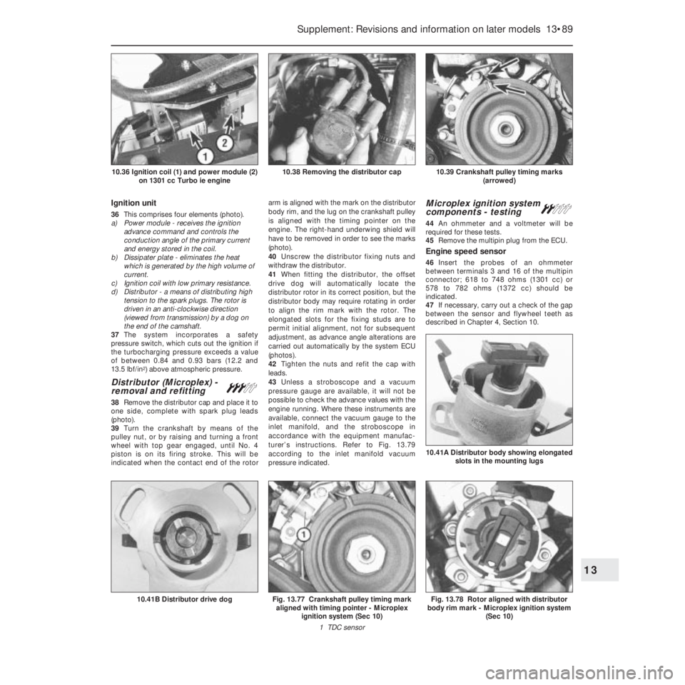
36This comprises four elements (photo).
a) Power module - receives the ignition
advance command and controls the
conduction angle of the primary current
and energy stored in the coil.
b) Dissipater plate - eliminates the heat
which is generated by the high volume of
current.
c) Ignition coil with low primary resistance.
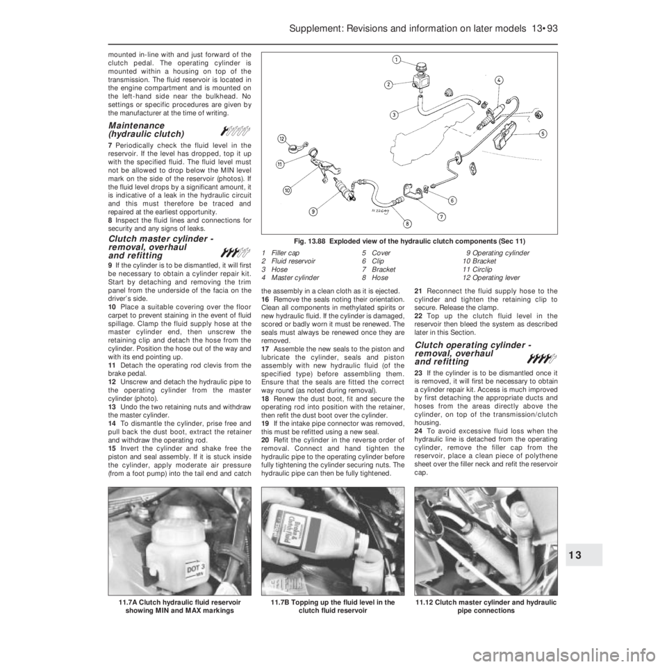
d) Distributor - a means of distributing high
tension to the spark plugs. The rotor is
driven in an anti-clockwise direction
(viewed from transmission) by a dog on
the end of the camshaft.
37The system incorporates a safety
pressure switch, which cuts out the ignition if
the turbocharging pressure exceeds a value
of between 0.84 and 0.93 bars (12.2 and
13.5 lbf/in
2) above atmospheric pressure.
Distributor (Microplex) -
removal and refitting#
38Remove the distributor cap and place it to
one side, complete with spark plug leads
(photo).
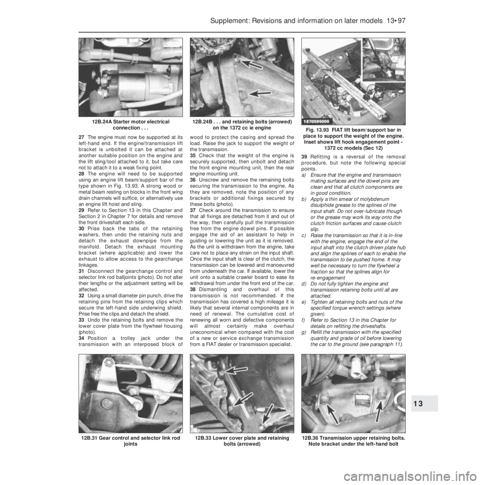
39Turn the crankshaft by means of the
pulley nut, or by raising and turning a front
wheel with top gear engaged, until No. 4
piston is on its firing stroke. This will be
indicated when the contact end of the rotorarm is aligned with the mark on the distributor
body rim, and the lug on the crankshaft pulley
is aligned with the timing pointer on the
engine. The right-hand underwing shield will
have to be removed in order to see the marks
(photo).
40Unscrew the distributor fixing nuts and
withdraw the distributor.
41When fitting the distributor, the offset
drive dog will automatically locate the
distributor rotor in its correct position, but the
distributor body may require rotating in order
to align the rim mark with the rotor. The
elongated slots for the fixing studs are to
permit initial alignment, not for subsequent
adjustment, as advance angle alterations are
carried out automatically by the system ECU
(photos).
42Tighten the nuts and refit the cap with
leads.
43Unless a stroboscope and a vacuum
pressure gauge are available, it will not be
possible to check the advance values with the
engine running. Where these instruments are
available, connect the vacuum gauge to the
inlet manifold, and the stroboscope in
accordance with the equipment manufac-
turer’s instructions. Refer to Fig. 13.79
according to the inlet manifold vacuum
pressure indicated.
Microplex ignition system
components - testing ª
44An ohmmeter and a voltmeter will be
required for these tests.
45Remove the multipin plug from the ECU.
Engine speed sensor
46Insert the probes of an ohmmeter
between terminals 3 and 16 of the multipin
connector; 618 to 748 ohms (1301 cc) or
578 to 782 ohms (1372 cc) should be
indicated.
47If necessary, carry out a check of the gap
between the sensor and flywheel teeth as
described in Chapter 4, Section 10.
Supplement: Revisions and information on later models 13•89
10.39 Crankshaft pulley timing marks
(arrowed)10.38 Removing the distributor cap10.36 Ignition coil (1) and power module (2)
on 1301 cc Turbo ie engine
Fig. 13.78 Rotor aligned with distributor
body rim mark - Microplex ignition system
(Sec 10)
10.41A Distributor body showing elongated
slots in the mounting lugs
Fig. 13.77 Crankshaft pulley timing mark
aligned with timing pointer - Microplex
ignition system (Sec 10)
1 TDC sensor10.41B Distributor drive dog
13
Page 215 of 303

TDC sensor
48Insert the probes of the ohmmeter
between terminals 1 and 2 of the multipin
connector; 618 to 748 ohms (1301 cc) or 578
to 782 ohms (1372 cc) should be indicated.
49If necessary, carry out a check of the gap
between the sensor and the crankshaft pulley,
as described in Chapter 4, Section 10.
ECU supply
50Switch on the ignition, and then insert the
probes of a voltmeter between terminals 13
and 11 of the multipin connector. Battery
voltage should be indicated. If not, check the
battery earth, ignition switch or intermediate
connector plug for security.
Power module supply (1301 cc)
51Pull the multipin plug from the powermodule, and connect the probes of a
voltmeter between terminal 4 of the connector
and earth. If the reading is less than battery
voltage, check the security of all connections
between the ignition switch and terminal + 15
of the ignition coil.
52Reconnect the multipin connector to the
ECU, but have the one from the power
module disconnected, and then switch on the
ignition.
53Connect the voltmeter between terminals
4 and 2 of the power module multipin
connector. If the indicated voltage is less than
battery voltage, check the security of all
connections between the ignition switch and
terminal + 15 of the ignition coil, and the
battery earth. If all are satisfactory, check for
continuity between terminals 11 and 12. If
continuity is broken, renew the ECU.
Power module (1372 cc)
54Proceed as described in paragraph 53.
Anti-knock sensor
55If “pinking” occurs, or loss of power is
noticed, test the sensor by substitution of a
new one.
Ignition coil
56Disconnect the leads from terminals 1
and 15 on the coil before testing.
57Using the ohmmeter, check the resistance
of the primary winding. This should be
between 0.31 and 0.37 ohms (1301 cc) or
0.40 to 0.49 ohms (1372 cc), at an ambient
temperature of 20ºC (68ºF).
58The secondary winding resistance should
be between 3330 and 4070 ohms (1301 cc) or
4320 to 5280 ohms (1372 cc), at an ambient
temperature of 20ºC (68ºF).
Distributor
59Check the resistance of the rotor arm,
which should be between 800 and
1200 ohms.
60Where all the foregoing tests have proved
satisfactory, then any problem must be due to
a fault in either the power module or the ECU.
These components can only be checked by
the substitution of a new unit - power module
first, then the ECU.
Safety pressure switch
61The device protects the engine from
excessive turbocharging pressure, cutting off
the ignition by earthing the Microplex ECU.
Testing is not possible without a special
pressure pump, so the easiest way to check a
suspected fault is to fit a new unit.
Digiplex 2 ignition system -
description
62This system operates in a similar manner
to that of the earlier type described in Chap-
ter 4, but the circuit layout differs to suit the
Mono Jetronic fuel injection system. In
operation, the main difference is that the
Digiplex 2 system has a greater number of
13•90 Supplement: Revisions and information on later models
Fig. 13.81 Microplex ignition system
control unit connection (Sec 10)
For colour code, see main wiring diagramsFig. 13.80 Microplex ignition system ECU multipin connector (Sec 10)
For colour code, see main wiring diagrams
Fig. 13.79 Ignition advance curves - Microplex ignition system on the 1301 cc Turbo ie
(Sec 10)
Page 216 of 303

advance points than the earlier system.
Comparison of Fig. 13.82 with Fig. 4.2
illustrates the difference in layout. Note that
the distributor is mounted on the rear end of
the cylinder head and is driven by the
camshaft.
63When working on the Digiplex 2 ignition
system or associated components, the
precautionary notes outlined in Section 9 of
Chapter 4 must be adhered to.
64As with the earlier system, test
procedures possible on the Digiplex 2 system
are restricted due to the need for specialised
testing equipment. The following checks are
possible, however, using a conventional test
meter.
Ignition coil check
65To check the resistance of the coil’s
primary windings, connect the probes of an
ohmmeter between the positive terminal and
the negative terminal as shown in Fig. 13.83,
and check that the resistance reading at 18 to
28ºC is 0.45 ohms ± 10% (photo).66To check the resistance of the coil’s
secondary windings, connect the probes of an
ohmmeter between the positive terminal and
the HT lead terminal as shown in Fig. 13.84.
Check that the resistance reading at 18 to
28ºC (64 to 82ºF) is 4800 ohms ± 10%.
Ignition timing check
67Refer to paragraph 2 in this Section.
Engine speed and TDC sensor check
68To check the resistance between the
sensor and the ECU, detach the wiring
connector (photo). Connect the probes of an
ohmmeter to the connector terminals and
check that the resistance reading is between
600 and 760 ohms at 20ºC (68ºF). If the
reading is not as specified, the sensor must
be renewed.
69The gap between the sensor and the pins
on the rear face of the flywheel must be
between 0.2 and 0.8 mm. Any deviation
outside of this clearance will be due to
mechanical damage to the sensor andnecessitates its renewal. The sensor is
accurately positioned during manufacture and
secured with tamperproof screws; it does not
require any adjustment during servicing. If it is
necessary to renew the sensor, a special gap
setting tool is required and the task is
therefore best entrusted to a FIAT dealer.
Supplement: Revisions and information on later models 13•91
Fig. 13.82 Digiplex 2 ignition system wiring circuits and components (Sec 10)
10.68 ECU location on the 1372 cc ie
engine10.65 Ignition coil and connections on the
1372 cc ie engineFig. 13.84 Test connections for ignition
coil secondary windings check - Digiplex 2
ignition system (Sec 10)
Fig. 13.83 Test connections for ignition
coil primary windings check - Digiplex 2
ignition system (Sec 10)
13
1 Connection point (lines connected to
the intake manifold)
2 ECU
3 Ignition coil
4 Distributor
5 Engine flywheel (with
five pins)
6 On/off switch (if fitted)
for advance reduction
7 On/off switch 2 (if fitted)
for curves
8 Battery
9 Spark plugs
10 Tachometer
11 Diagnostic socket
12 Engine speed and TDC sensor
13 To check actuator idle speed
14 To terminal no. 1 of injection control unit
(rpm signal)
Page 218 of 303
mounted in-line with and just forward of the
clutch pedal. The operating cylinder is
mounted within a housing on top of the
transmission. The fluid reservoir is located in
the engine compartment and is mounted on
the left-hand side near the bulkhead. No
settings or specific procedures are given by
the manufacturer at the time of writing.
Maintenance
(hydraulic clutch)Á
7Periodically check the fluid level in the
reservoir. If the level has dropped, top it up
with the specified fluid. The fluid level must
not be allowed to drop below the MIN level
mark on the side of the reservoir (photos). If
the fluid level drops by a significant amount, it
is indicative of a leak in the hydraulic circuit
and this must therefore be traced and
repaired at the earliest opportunity.
8Inspect the fluid lines and connections for
security and any signs of leaks.
Clutch master cylinder -
removal, overhaul
and refitting
#
9If the cylinder is to be dismantled, it will first
be necessary to obtain a cylinder repair kit.
Start by detaching and removing the trim
panel from the underside of the facia on the
driver’s side.
10Place a suitable covering over the floor
carpet to prevent staining in the event of fluid
spillage. Clamp the fluid supply hose at the
master cylinder end, then unscrew the
retaining clip and detach the hose from the
cylinder. Position the hose out of the way and
with its end pointing up.
11Detach the operating rod clevis from the
brake pedal.
12Unscrew and detach the hydraulic pipe to
the operating cylinder from the master
cylinder (photo).
13Undo the two retaining nuts and withdraw
the master cylinder.
14To dismantle the cylinder, prise free and
pull back the dust boot, extract the retainer
and withdraw the operating rod.
15Invert the cylinder and shake free the
piston and seal assembly. If it is stuck inside
the cylinder, apply moderate air pressure
(from a foot pump) into the tail end and catchthe assembly in a clean cloth as it is ejected.
16Remove the seals noting their orientation.
Clean all components in methylated spirits or
new hydraulic fluid. If the cylinder is damaged,
scored or badly worn it must be renewed. The
seals must always be renewed once they are
removed.
17Assemble the new seals to the piston and
lubricate the cylinder, seals and piston
assembly with new hydraulic fluid (of the
specified type) before assembling them.
Ensure that the seals are fitted the correct
way round (as noted during removal).
18Renew the dust boot, fit and secure the
operating rod into position with the retainer,
then refit the dust boot over the cylinder.
19If the intake pipe connector was removed,
this must be refitted using a new seal.
20Refit the cylinder in the reverse order of
removal. Connect and hand tighten the
hydraulic pipe to the operating cylinder before
fully tightening the cylinder securing nuts. The
hydraulic pipe can then be fully tightened.21Reconnect the fluid supply hose to the
cylinder and tighten the retaining clip to
secure. Release the clamp.
22Top up the clutch fluid level in the
reservoir then bleed the system as described
later in this Section.
Clutch operating cylinder -
removal, overhaul
and refitting
¢
23If the cylinder is to be dismantled once it
is removed, it will first be necessary to obtain
a cylinder repair kit. Access is much improved
by first detaching the appropriate ducts and
hoses from the areas directly above the
cylinder, on top of the transmission/clutch
housing.
24To avoid excessive fluid loss when the
hydraulic line is detached from the operating
cylinder, remove the filler cap from the
reservoir, place a clean piece of polythene
sheet over the filler neck and refit the reservoir
cap.
Supplement: Revisions and information on later models 13•93
Fig. 13.88 Exploded view of the hydraulic clutch components (Sec 11)
1 Filler cap
2 Fluid reservoir
3 Hose
4 Master cylinder5 Cover
6 Clip
7 Bracket
8 Hose9 Operating cylinder
10 Bracket
11 Circlip
12 Operating lever
11.12 Clutch master cylinder and hydraulic
pipe connections11.7B Topping up the fluid level in the
clutch fluid reservoir11.7A Clutch hydraulic fluid reservoir
showing MIN and MAX markings
13
Page 222 of 303
27The engine must now be supported at its
left-hand end. If the engine/transmission lift
bracket is unbolted it can be attached at
another suitable position on the engine and
the lift sling/tool attached to it, but take care
not to attach it to a weak fixing point.
28The engine will need to be supported
using an engine lift beam/support bar of the
type shown in Fig. 13.93. A strong wood or
metal beam resting on blocks in the front wing
drain channels will suffice, or alternatively use
an engine lift hoist and sling.
29Refer to Section 13 in this Chapter and
Section 2 in Chapter 7 for details and remove
the front driveshaft each side.
30Prise back the tabs of the retaining
washers, then undo the retaining nuts and
detach the exhaust downpipe from the
manifold. Detach the exhaust mounting
bracket (where applicable) and lower the
exhaust to allow access to the gearchange
linkages.
31Disconnect the gearchange control and
selector link rod balljoints (photo). Do not alter
their lengths or the adjustment setting will be
affected.
32Using a small diameter pin punch, drive the
retaining pins from the retaining clips which
secure the left-hand side underwing shield.
Prise free the clips and detach the shield.
33Undo the retaining bolts and remove the
lower cover plate from the flywheel housing
(photo).
34Position a trolley jack under the
transmission with an interposed block ofwood to protect the casing and spread the
load. Raise the jack to support the weight of
the transmission.
35Check that the weight of the engine is
securely supported, then unbolt and detach
the front engine mounting unit, then the rear
engine mounting unit.
36Unscrew and remove the remaining bolts
securing the transmission to the engine. As
they are removed, note the position of any
brackets or additional fixings secured by
these bolts (photo).
37Check around the transmission to ensure
that all fixings are detached from it and out of
the way, then carefully pull the transmission
free from the engine dowel pins. If possible
engage the aid of an assistant to help in
guiding or lowering the unit as it is removed.
As the unit is withdrawn from the engine, take
care not to place any strain on the input shaft.
Once the input shaft is clear of the clutch, the
transmission can be lowered and manoeuvred
from underneath the car. If available, lower the
unit onto a suitable crawler board to ease its
withdrawal from under the front end of the car.
38Dismantling and overhaul of this
transmission is not recommended. If the
transmission has covered a high mileage it is
likely that several internal components are in
need of renewal. The cumulative cost of
renewing all worn and defective components
will almost certainly make overhaul
uneconomical when compared with the cost
of a new or service exchange transmission
from a FIAT dealer or transmission specialist.39Refitting is a reversal of the removal
procedure, but note the following special
points.
a) Ensure that the engine and transmission
mating surfaces and the dowel pins are
clean and that all clutch components are
in good condition.
b) Apply a thin smear of molybdenum
disulphide grease to the splines of the
input shaft. Do not over-lubricate though
or the grease may work its way onto the
clutch friction surfaces and cause clutch
slip.
c) Raise the transmission so that it is in-line
with the engine, engage the end of the
input shaft into the clutch driven plate hub
and align the splines of each to enable the
transmission to be pushed home. It may
well be necessary to turn the flywheel a
fraction so that the splines align for
re-engagement
d) Do not fully tighten the engine and
transmission retaining bolts until all are
attached.
e) Tighten all retaining bolts and nuts of the
specified torque wrench settings (where
given).
f) Refer to Section 13 in this Chapter for
details on refitting the driveshafts.
g) Refill the transmission with the specified
quantity and grade of oil before lowering
the car to the ground (see paragraph 11).
Supplement: Revisions and information on later models 13•97
Fig. 13.93 FIAT lift beam/support bar in
place to support the weight of the engine.
Inset shows lift hook engagement point -
1372 cc models (Sec 12)
12B.24B . . . and retaining bolts (arrowed)
on the 1372 cc ie engine12B.24A Starter motor electrical
connection . . .
12B.36 Transmission upper retaining bolts.
Note bracket under the left-hand bolt12B.33 Lower cover plate and retaining
bolts (arrowed)12B.31 Gear control and selector link rod
joints
13
Page 227 of 303
14B.54 Master cylinder/vacuum servo
located next to the coolant expansion tank
(1301 cc Turbo ie model)
29Fit the new pads, complete with anti-rattle
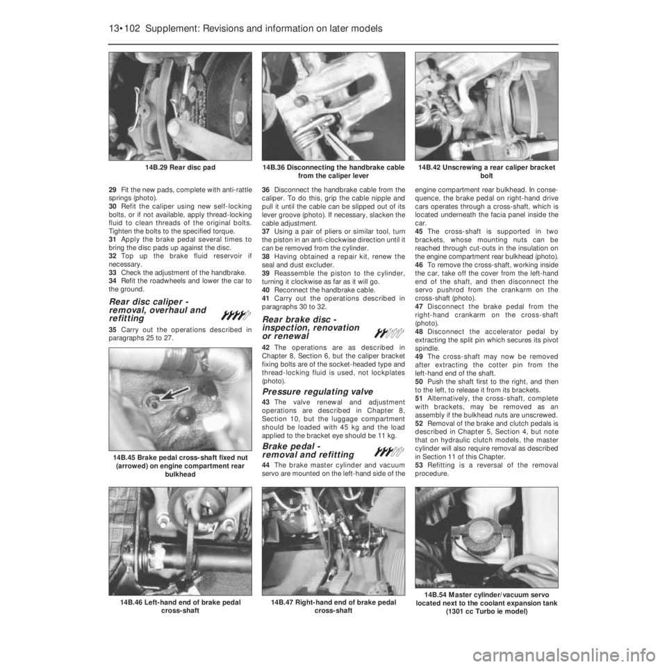
springs (photo).
30Refit the caliper using new self-locking
bolts, or if not available, apply thread-locking
fluid to clean threads of the original bolts.
Tighten the bolts to the specified torque.
31Apply the brake pedal several times to
bring the disc pads up against the disc.
32Top up the brake fluid reservoir if
necessary.
33Check the adjustment of the handbrake.
34Refit the roadwheels and lower the car to
the ground.
Rear disc caliper -
removal, overhaul and
refitting
¢
35Carry out the operations described in
paragraphs 25 to 27.36Disconnect the handbrake cable from the
caliper. To do this, grip the cable nipple and
pull it until the cable can be slipped out of its
lever groove (photo). If necessary, slacken the
cable adjustment.
37Using a pair of pliers or similar tool, turn
the piston in an anti-clockwise direction until it
can be removed from the cylinder.
38Having obtained a repair kit, renew the
seal and dust excluder.
39Reassemble the piston to the cylinder,
turning it clockwise as far as it will go.
40Reconnect the handbrake cable.
41Carry out the operations described in
paragraphs 30 to 32.
Rear brake disc -
inspection, renovation
or renewal
ª
42The operations are as described in
Chapter 8, Section 6, but the caliper bracket
fixing bolts are of the socket-headed type and
thread-locking fluid is used, not lockplates
(photo).
Pressure regulating valve
43The valve renewal and adjustment
operations are described in Chapter 8,
Section 10, but the luggage compartment
should be loaded with 45 kg and the load
applied to the bracket eye should be 11 kg.
Brake pedal -
removal and refitting#
44The brake master cylinder and vacuum
servo are mounted on the left-hand side of theengine compartment rear bulkhead. In conse-
quence, the brake pedal on right-hand drive
cars operates through a cross-shaft, which is
located underneath the facia panel inside the
car.
45The cross-shaft is supported in two
brackets, whose mounting nuts can be
reached through cut-outs in the insulation on
the engine compartment rear bulkhead (photo).
46To remove the cross-shaft, working inside
the car, take off the cover from the left-hand
end of the shaft, and then disconnect the
servo pushrod from the crankarm on the
cross-shaft (photo).
47Disconnect the brake pedal from the
right-hand crankarm on the cross-shaft
(photo).
48Disconnect the accelerator pedal by
extracting the split pin which secures its pivot
spindle.
49The cross-shaft may now be removed
after extracting the cotter pin from the
left-hand end of the shaft.
50Push the shaft first to the right, and then
to the left, to release it from its brackets.
51Alternatively, the cross-shaft, complete
with brackets, may be removed as an
assembly if the bulkhead nuts are unscrewed.
52Removal of the brake and clutch pedals is
described in Chapter 5, Section 4, but note
that on hydraulic clutch models, the master
cylinder will also require removal as described
in Section 11 of this Chapter.
53Refitting is a reversal of the removal
procedure.
13•102 Supplement: Revisions and information on later models
14B.47 Right-hand end of brake pedal
cross-shaft14B.46 Left-hand end of brake pedal
cross-shaft
14B.45 Brake pedal cross-shaft fixed nut
(arrowed) on engine compartment rear
bulkhead
14B.42 Unscrewing a rear caliper bracket
bolt14B.36 Disconnecting the handbrake cable
from the caliper lever14B.29 Rear disc pad
Page 228 of 303
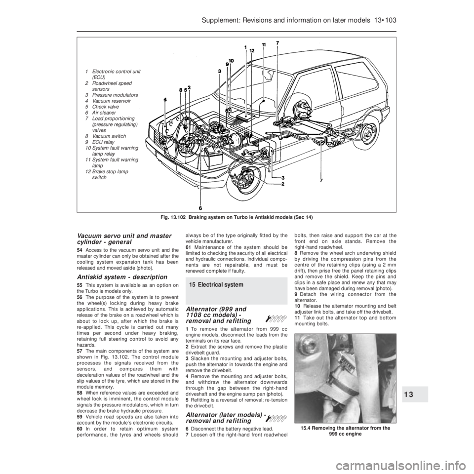
Vacuum servo unit and master
cylinder - general
54Access to the vacuum servo unit and the
master cylinder can only be obtained after the
cooling system expansion tank has been
released and moved aside (photo).
Antiskid system - description
55This system is available as an option on
the Turbo ie models only.
56The purpose of the system is to prevent
the wheel(s) locking during heavy brake
applications. This is achieved by automatic
release of the brake on a roadwheel which is
about to lock up, after which the brake is
re-applied. This cycle is carried out many
times per second under heavy braking,
retaining full steering control to avoid any
hazards.
57The main components of the system are
shown in Fig. 13.102. The control module
processes the signals received from the
sensors, and compares them with
deceleration values of the roadwheel and the
slip values of the tyre, which are stored in the
module memory.
58When reference values are exceeded and
wheel lock is imminent, the control module
signals the pressure modulators, which in turn
decrease the brake hydraulic pressure.
59Vehicle road speeds are also taken into
account by the module’s electronic circuits.
60In order to retain optimum system
performance, the tyres and wheels shouldalways be of the type originally fitted by the
vehicle manufacturer.
61Maintenance of the system should be
limited to checking the security of all electrical
and hydraulic connections. Individual compo-
nents are not repairable, and must be
renewed complete if faulty.15 Electrical system
Alternator (999 and
1108 cc models) -
removal and refitting
Á
1To remove the alternator from 999 cc
engine models, disconnect the leads from the
terminals on its rear face.
2Extract the screws and remove the plastic
drivebelt guard.
3Slacken the mounting and adjuster bolts,
push the alternator in towards the engine and
remove the drivebelt.
4Remove the mounting and adjuster bolts,
and withdraw the alternator downwards
through the gap between the right-hand
driveshaft and the engine sump pan (photo).
5Refitting is a reversal of removal; re-tension
the drivebelt.
Alternator (later models) -
removal and refitting Á
6Disconnect the battery negative lead.
7Loosen off the right-hand front roadwheelbolts, then raise and support the car at the
front end on axle stands. Remove the
right-hand roadwheel.
8Remove the wheel arch underwing shield
by driving the compression pins from the
centre of the retaining clips (using a 2 mm
drift), then prise free the panel retaining clips
and remove the shield. Keep the pins and
clips in a safe place and renew any that may
have been damaged during removal (photo).
9Detach the wiring connector from the
alternator.
10Release the alternator mounting and belt
adjuster link bolts, and take off the drivebelt.
11Take out the alternator top and bottom
mounting bolts.
Supplement: Revisions and information on later models 13•103
15.4 Removing the alternator from the
999 cc engine
Fig. 13.102 Braking system on Turbo ie Antiskid models (Sec 14)
13
1 Electronic control unit
(ECU)
2 Roadwheel speed
sensors
3 Pressure modulators
4 Vacuum reservoir
5 Check valve
6 Air cleaner
7 Load proportioning
(pressure regulating)
valves
8 Vacuum switch
9 ECU relay
10 System fault warning
lamp relay
11 System fault warning
lamp
12 Brake stop lamp
switch
Page 231 of 303

adjustment procedures are the same as those
outlined for the previous model units in
Chapter 9, but ensure that the load
compensation lever is turned to the “O”
(normal load setting) position before making
any adjustments.
Headlamp unit removal - later
models
32The removal and refitting procedures
described in Chapter 9 also apply to the later
headlamp type, but note that later units are
secured in position by three retaining screws.
Headlamp dim-dip system -
description
33On later models, the wiring circuit has
been modified to prevent the car being drivenon parking lamps only in built-up areas.
34Headlamp intensity is reduced by the
transformer located at the front of the engine
compartment (photo).
35Any attempt to start the car with parking
lamps only on will automatically cause the
headlamps to switch on with a low-intensity
dipped beam. Dipped and main beam
function normally.
36The headlamp dim-dip system is a legal
requirement for all UK models registered after
April 1st, 1987.
Front fog lamps - bulb/unit
removal and refitting
and beam adjustment
ª
37Ensure that the front fog lamps are
switched off, then unscrew the two retainingscrews and withdraw the lamp unit from the
underside of the front bumper (photos).
38Undo the retaining screw and remove the
access cover from the unit (photo).
39Disconnect the wiring connector from the
bulb, release the clips and withdraw the bulb
from the lamp (photo).
40Refit in the reverse order of removal.
Check the light for satisfactory operation and
if the beam requires resetting, turn the
adjustment screw in the required direction.
41To adjust the beam, position the car 5 m
from, and square on to, a wall or similar.
42Measure the height of the centre of the
lamp lens from the ground and mark the
position on the wall. Switch on the lamp. The
demarcation line (cut-off) of the light should
be below the mark on the wall by 50 mm plus
one-third of the ground-to-lamp centre
measurement. Adjust the beam as required
using the long centre screw.
Horn - relocation
43The single horn, on applicable models, is
now located behind the grille, bolted on a
bracket attached to the top rail (photo).
Steering column combination
switches (later models) -
removal and refitting
Á
44Disconnect the battery negative lead.
45Undo the retaining screws and remove
the steering column shrouds (photos).
46Remove the steering wheel as described
in Chapter 10.
13•106 Supplement: Revisions and information on later models
15.45B . . . then remove the upper . . .15.45A Undo the retaining screws . . .15.43 Horn location
15.39 . . . detach the wires, extract the bulb15.38 . . . remove the rear cover . . .
15.37B . . . and withdraw the front fog lamp
unit . . .15.37A Undo the retaining bolts . . .15.34 Headlamp dim-dip transformer