1983 FIAT UNO diagram
[x] Cancel search: diagramPage 3 of 303
REPAIRS & OVERHAUL
Engine and Associated Systems
Engine (also see Chapter 13)Page 1•1
Cooling and heating systems (also see Chapter 13)Page2•1
Fuel system (also see Chapter 13)Page 3•1
Ignition system (also see Chapter 13)Page4•1
Transmission
Clutch (also see Chapter 13)Page5•1
Transmission (also see Chapter 13)Page6•1
Driveshafts, hubs, roadwheels and tyres (also see Chapter 13)Page7•1
Brakes
Braking system(also see Chapter 13)Page 8•1
Electrical
Electrical system(also see Chapter 13)Page 9•1
Steering and suspension
SteeringPage 10•1
Suspension (also see Chapter 13)Page 11•1
Bodywork
Bodywork (also see Chapter 13)Page 12•1
Additional information
Supplement: Revisions and information on later models Page 13•1
Wiring DiagramsPage 14•1
REFERENCE
MOT Test Checks PageREF•1
Tools and Working Facilities Page REF•5
General Repair Procedures Page REF•8
Fault FindingPage REF•9
Buying Spare Parts & Vehicle Identification Numbers PageREF•12
Glossary of Technical Terms PageREF•13
IndexPage REF•17
Contents
Page 40 of 303
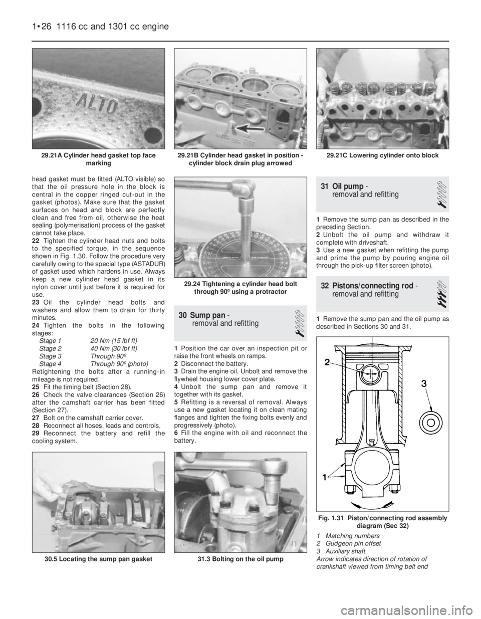
head gasket must be fitted (ALTO visible) so
that the oil pressure hole in the block is
central in the copper ringed cut-out in the
gasket (photos). Make sure that the gasket
surfaces on head and block are perfectly
clean and free from oil, otherwise the heat
sealing (polymerisation) process of the gasket
cannot take place.
22Tighten the cylinder head nuts and bolts
to the specified torque, in the sequence
shown in Fig. 1.30. Follow the procedure very
carefully owing to the special type (ASTADUR)
of gasket used which hardens in use. Always
keep a new cylinder head gasket in its
nylon cover until just before it is required for
use.
23Oil the cylinder head bolts and
washers and allow them to drain for thirty
minutes.
24Tighten the bolts in the following
stages:
Stage 1 20 Nm (15 lbf ft)
Stage 2 40 Nm (30 lbf ft)
Stage 3 Through 90º
Stage 4 Through 90º (photo)
Retightening the bolts after a running-in
mileage is not required.
25Fit the timing belt (Section 28).
26Check the valve clearances (Section 26)
after the camshaft carrier has been fitted
(Section 27).
27Bolt on the camshaft carrier cover.
28Reconnect all hoses, leads and controls.
29Reconnect the battery and refill the
cooling system.
30 Sump pan-
removal and refitting
1
1Position the car over an inspection pit or
raise the front wheels on ramps.
2Disconnect the battery.
3Drain the engine oil. Unbolt and remove the
flywheel housing lower cover plate.
4Unbolt the sump pan and remove it
together with its gasket.
5Refitting is a reversal of removal. Always
use a new gasket locating it on clean mating
flanges and tighten the fixing bolts evenly and
progressively (photo).
6Fill the engine with oil and reconnect the
battery.
31 Oil pump-
removal and refitting
1
1Remove the sump pan as described in the
preceding Section.
2Unbolt the oil pump and withdraw it
complete with driveshaft.
3Use a new gasket when refitting the pump
and prime the pump by pouring engine oil
through the pick-up filter screen (photo).
32 Pistons/connecting rod-
removal and refitting
3
1Remove the sump pan and the oil pump as
described in Sections 30 and 31.
1•26 1116 cc and 1301 cc engine
Fig. 1.31 Piston/connecting rod assembly
diagram (Sec 32)
1 Matching numbers
2 Gudgeon pin offset
3 Auxiliary shaft
Arrow indicates direction of rotation of
crankshaft viewed from timing belt end
29.24 Tightening a cylinder head bolt
through 90º using a protractor
31.3 Bolting on the oil pump30.5 Locating the sump pan gasket
29.21C Lowering cylinder onto block29.21B Cylinder head gasket in position -
cylinder block drain plug arrowed29.21A Cylinder head gasket top face
marking
Page 65 of 303
7 Carburettor idle speed and
mixture- adjustment
4
1All carburettors have their mixture
adjustment set in production. The screw is
fitted with a tamperproof cap.
2Under normal circumstances, only the idle
speed screw need be adjusted to set the
engine idle speed to the specified level.
3Before attempting to adjust the idle speed
or mixture, it is important to have the ignition
and valve clearances correctly set and the
engine at normal operating temperature with
the air cleaner fitted.
4Where the mixture must be adjusted, prise
out the tamperproof plug and turn the mixture
screw in to weaken or out to enrich the
mixture until the engine runs smoothly without
any tendency to “hunt”.
5Ideally an exhaust gas analyser should be
used to make sure that the CO level is within
the specified range.
6Once the mixture has been correctly set,
re-adjust the idle speed screw.
8 Carburettor-
removal and refitting
2
1Remove the air cleaner.
2Disconnect the flow and return fuel hoses
from the carburettor and plug them.3Disconnect the coolant hoses from the
carburettor throttle valve plate block.
Provided the cooling system is cold and not
under pressure there should be almost no loss
of coolant. Tie the hoses up as high as
possible with a piece of wire.
4Disconnect the vacuum and vent hoses
from the carburettor.
5Disconnect the throttle and choke controls
from the carburettor.
6Unscrew the mounting flange nuts and lift
the carburettor from the intake manifold
(photo).
7Refitting is a reversal of removal. Use a new
flange gasket and make sure that the fuel
return hose is routed above the air cleaner
intake.
9 Carburettor
(Weber 32 ICEV 50/250/1)-
servicing and adjustment
4
1The carburettor top cover with float may be
removed without the need to withdraw the
carburettor from the manifold. The other
adjustments described will require removal of
the carburettor.
2Unscrew the filter plug from the top cover,
clean the filter screen and refit it.
3Extract the top cover fixing screws, lift the
cover and tilt it to unhook it from the
diaphragm capsule link rod.
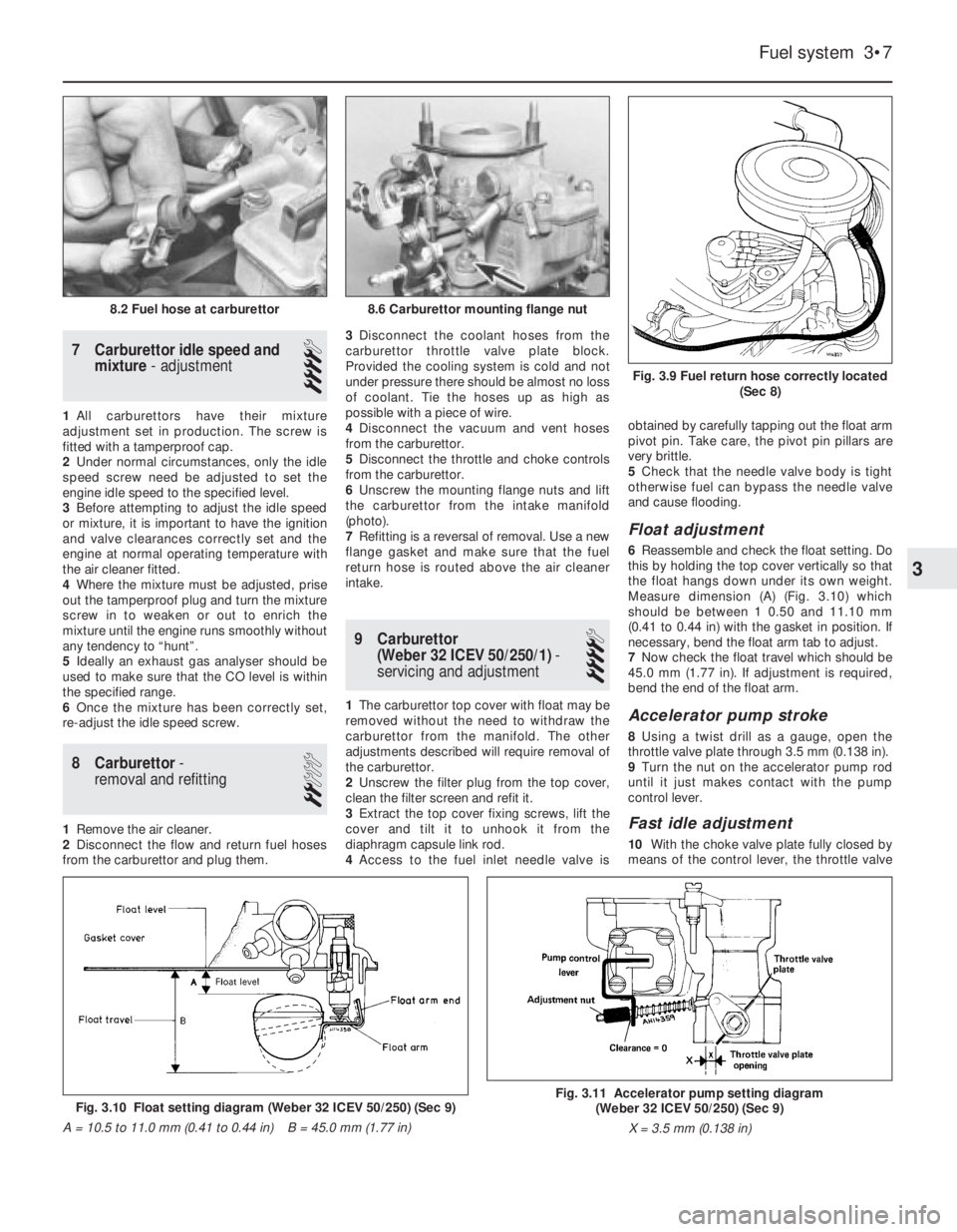
4Access to the fuel inlet needle valve isobtained by carefully tapping out the float arm
pivot pin. Take care, the pivot pin pillars are
very brittle.
5Check that the needle valve body is tight
otherwise fuel can bypass the needle valve
and cause flooding.
Float adjustment
6Reassemble and check the float setting. Do
this by holding the top cover vertically so that
the float hangs down under its own weight.
Measure dimension (A) (Fig. 3.10) which
should be between 1 0.50 and 11.10 mm
(0.41 to 0.44 in) with the gasket in position. If
necessary, bend the float arm tab to adjust.
7Now check the float travel which should be
45.0 mm (1.77 in). If adjustment is required,
bend the end of the float arm.
Accelerator pump stroke
8Using a twist drill as a gauge, open the
throttle valve plate through 3.5 mm (0.138 in).
9Turn the nut on the accelerator pump rod
until it just makes contact with the pump
control lever.
Fast idle adjustment
10With the choke valve plate fully closed by
means of the control lever, the throttle valve
Fuel system 3•7
Fig. 3.9 Fuel return hose correctly located
(Sec 8)
8.6 Carburettor mounting flange nut8.2 Fuel hose at carburettor
Fig. 3.10 Float setting diagram (Weber 32 ICEV 50/250) (Sec 9)
A = 10.5 to 11.0 mm (0.41 to 0.44 in) B = 45.0 mm (1.77 in)Fig. 3.11 Accelerator pump setting diagram
(Weber 32 ICEV 50/250) (Sec 9)
X = 3.5 mm (0.138 in)
3
Page 66 of 303
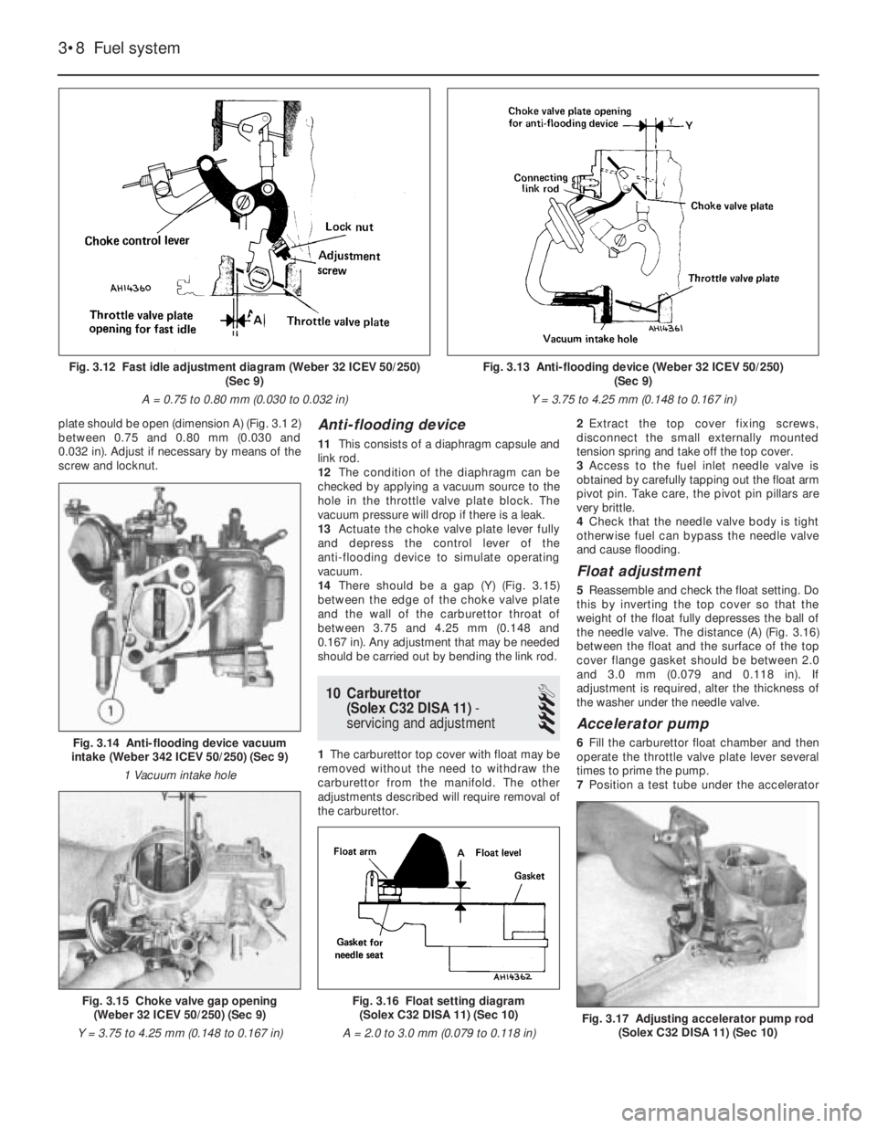
plate should be open (dimension A) (Fig. 3.1 2)
between 0.75 and 0.80 mm (0.030 and
0.032 in). Adjust if necessary by means of the
screw and locknut.Anti-flooding device
11This consists of a diaphragm capsule and
link rod.
12The condition of the diaphragm can be
checked by applying a vacuum source to the
hole in the throttle valve plate block. The
vacuum pressure will drop if there is a leak.
13Actuate the choke valve plate lever fully
and depress the control lever of the
anti-flooding device to simulate operating
vacuum.
14There should be a gap (Y) (Fig. 3.15)
between the edge of the choke valve plate
and the wall of the carburettor throat of
between 3.75 and 4.25 mm (0.148 and
0.167 in). Any adjustment that may be needed
should be carried out by bending the link rod.
10 Carburettor
(Solex C32 DISA 11)-
servicing and adjustment
4
1The carburettor top cover with float may be
removed without the need to withdraw the
carburettor from the manifold. The other
adjustments described will require removal of
the carburettor.2Extract the top cover fixing screws,
disconnect the small externally mounted
tension spring and take off the top cover.
3Access to the fuel inlet needle valve is
obtained by carefully tapping out the float arm
pivot pin. Take care, the pivot pin pillars are
very brittle.
4Check that the needle valve body is tight
otherwise fuel can bypass the needle valve
and cause flooding.
Float adjustment
5Reassemble and check the float setting. Do
this by inverting the top cover so that the
weight of the float fully depresses the ball of
the needle valve. The distance (A) (Fig. 3.16)
between the float and the surface of the top
cover flange gasket should be between 2.0
and 3.0 mm (0.079 and 0.118 in). If
adjustment is required, alter the thickness of
the washer under the needle valve.
Accelerator pump
6Fill the carburettor float chamber and then
operate the throttle valve plate lever several
times to prime the pump.
7Position a test tube under the accelerator
3•8 Fuel system
Fig. 3.16 Float setting diagram
(Solex C32 DISA 11) (Sec 10)
A = 2.0 to 3.0 mm (0.079 to 0.118 in)
Fig. 3.17 Adjusting accelerator pump rod
(Solex C32 DISA 11) (Sec 10)
Fig. 3.15 Choke valve gap opening
(Weber 32 ICEV 50/250) (Sec 9)
Y = 3.75 to 4.25 mm (0.148 to 0.167 in)
Fig. 3.14 Anti-flooding device vacuum
intake (Weber 342 ICEV 50/250) (Sec 9)
1 Vacuum intake hole
Fig. 3.12 Fast idle adjustment diagram (Weber 32 ICEV 50/250)
(Sec 9)
A = 0.75 to 0.80 mm (0.030 to 0.032 in)Fig. 3.13 Anti-flooding device (Weber 32 ICEV 50/250)
(Sec 9)
Y = 3.75 to 4.25 mm (0.148 to 0.167 in)
Page 67 of 303

pump jet and give ten full strokes of the
throttle lever, pausing between each stroke to
allow fuel to finish dripping.
8The total volume of fuel collected should be
between 2.5 and 4.5 cc. Adjust the nut on the
pump control and if necessary to increase or
decrease the volume of fuel ejected.
Fast idle adjustment
9With the choke valve plate fully closed, the
throttle valve plate should be open to give a
dimension (X) (Fig. 3.18) of between 0.90 and
1.0 mm (0.035 to 0.039 in). Use a twist drill of
suitable diameter to measure the gap. If
necessary, adjust by means of the screw and
locknut.
Anti-flooding device
10Close the choke valve plate by means of
the control lever. At the same time, push the
lean out valve rod towards the valve.
11There should be a gap (X) (Fig. 3.19)
between the edge of the choke valve plateand the carburettor throat of between 4.75
and 5.25 mm (0.187 to 0.207 in). Adjust if
necessary by means of the screw and locknut
on the lean out valve.
11 Carburettors (Weber 32 ICEE/
250 and Solex C32 DISA 14)-
description and adjustment
4
1One of these carburettors is used on
903 cc ES engines. They are very similar to
the Weber 32 ICEV 50/250 and Solex
C32 DISA 11 already described in this
Chapter except that a fuel cut-out solenoid
valve is fitted in association with the Digiplex
ignition system (see Chapters 4 and 9).
2The solenoid valve cuts off the supply of
fuel to the carburettor whenever the
accelerator pedal is released during overrun
conditions.
3A fuel cut-out device control unit receives
information regarding engine speed from the
static ignition control unit.
4A throttle butterfly switch relays informationthat the accelerator pedal is in the released
state.
5At certain minimum idle speeds during
deceleration, the fuel cut-out solenoid valve is
re-energised so that engine idling is
maintained without the tendency to cut out.
6The Solex type control unit varies the fuel
cut-out point according to the deceleration
value.Fault testing
7Should a fault develop, connect a test lamp
between the fuel cut-out solenoid switch and
a good earth.
8Connect a reliable tachometer to the engine
in accordance with the maker’s instructions.
9Start the engine and raise its speed to
between 3000 and 4000 rev/min, then fully
release the accelerator pedal.
10The test lamp should only go out during
the period when the accelerator pedal is
released. Should the test lamp remain on all
the time, or never come on, check the throttle
switch earth and the solenoid switch
connections.
11Disconnect the multi-plug from the control
unit. Switch on the ignition and check that a
test lamp connected between contact 7 of the
multi-plug and earth will illuminate. If it does
not, there is an open circuit from connection
15/54 of the fuel cut-off switch.
12Switch off the ignition and check for
continuity between contact 3 of the multiplug
and earth. An ohmmeter will be required for
this test.
13If there is no continuity (ohmmeter shows
infinity), check all the system earth
connections. Also check that the wiring plug
under the control unit is properly connected.
14Finally, check the engine speed signal. To
do this, a tachometer must be connected to
the single socket under the control unit within
the engine compartment.
15If the tachometer registers correctly then
this confirms that the electronic ignition
Fuel system 3•9
Fig. 3.18 Fast idle adjustment diagram (Solex C32 DISA 11)
(Sec 10)
X = 0.90 to 1.0 mm (0.035 to 0.039 in)Fig. 3.19 Anti-flooding device adjustment diagram
(Solex C32 DISA 11) (Sec 10)
X = 4.75 to 5.25 mm (0.187 to 0.207 in)
Fig. 3.21 Sectional view of fuel cut-off
switch (Solex C32 DISA 14) (Sec 11)
Fig. 3.20 Moving lean out valve rod
(Solex C32 DISA 11) (Sec 10)
X = 4.75 to 5.25 mm (0.187 to 0.207 in)
3
Page 68 of 303
control unit is functioning, if the tachometer
does not register, renew the ignition control
unit.
16If a replacement carburettor is to be fitted,
only fit the Solex assembly including the
control module, even if a Weber was originally
fitted.
12 Carburettor
(Weber 32 ICEV 51/250)-
servicing and adjustment
4
1This carburettor, fitted to 1116 cc engines,
is very similar to the unit described in Sec-
tion 9.
2The fast idle adjustment procedure is
identical, but note that dimension (A) (Fig.
3.12) should be between 0.85 and 0.90 mm
(0.033 and 0.035 in).
3The choke valve plate gap (Y) (Fig. 3.13)
should be between 5.5 and 6.5 mm (0.22 and
0.26 in) and if adjustment is required, bend
the stop on the control lever.
13 Carburettor
(Solex C32 DISA 12)-
servicing and adjustment
4
1This carburettor is an alternative to the
Weber fitted to 1116 cc engines.
2The adjustments described in Section 9
apply.
14 Carburettor
(Weber 30/32 DMTR 90/250)
- servicing and adjustment
4
1The carburettor top cover with float may be
removed without the need to withdraw the
carburettor from the manifold. The other
adjustments described in this Section will
require removal of the carburettor.
2Extract the top cover fixing screws and lift
away the top cover with float. Access to the
fuel inlet needle valve is as described in
Section 9 paragraphs 4 and 5.
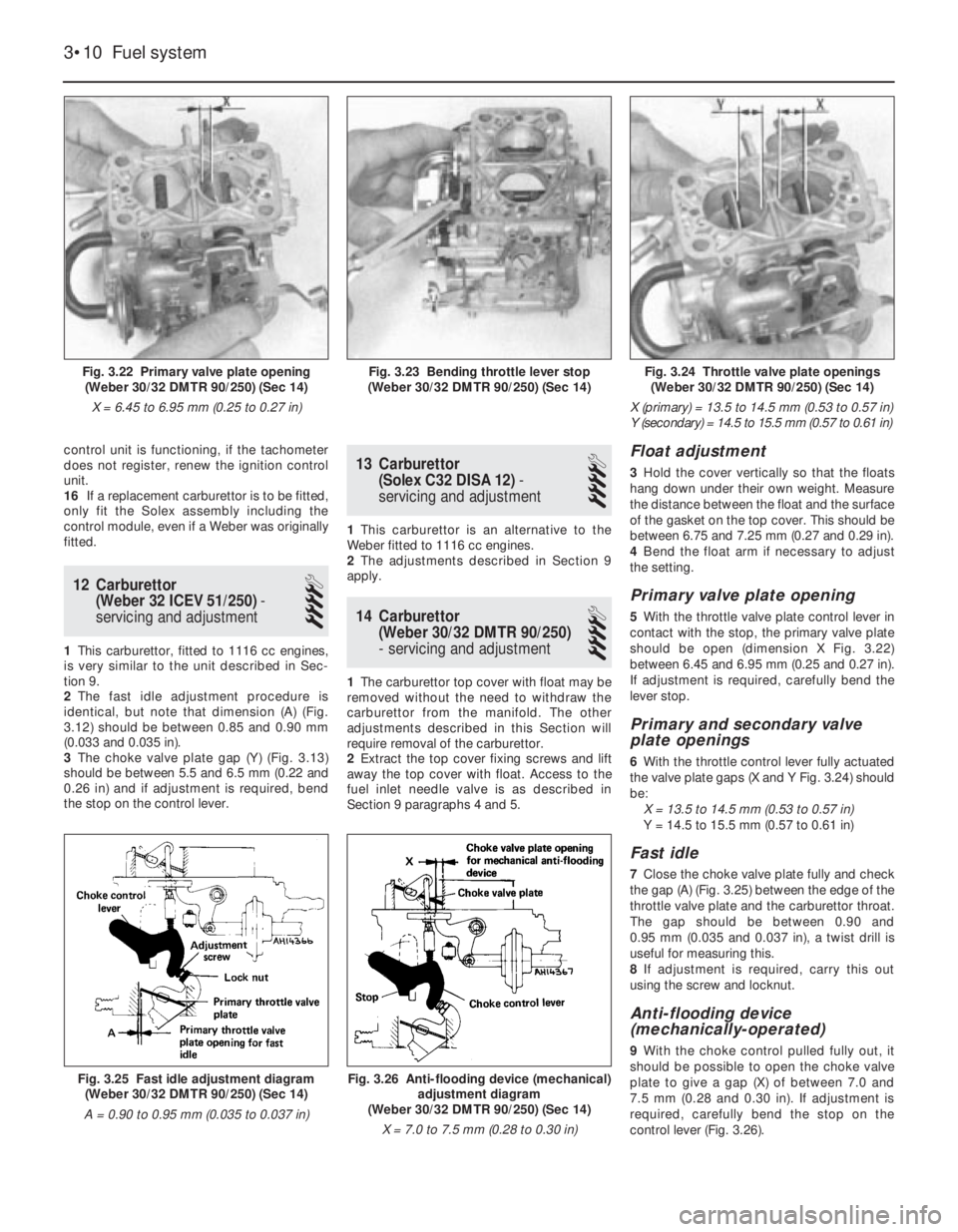
Float adjustment
3Hold the cover vertically so that the floats
hang down under their own weight. Measure
the distance between the float and the surface
of the gasket on the top cover. This should be
between 6.75 and 7.25 mm (0.27 and 0.29 in).
4Bend the float arm if necessary to adjust
the setting.
Primary valve plate opening
5With the throttle valve plate control lever in
contact with the stop, the primary valve plate
should be open (dimension X Fig. 3.22)
between 6.45 and 6.95 mm (0.25 and 0.27 in).
If adjustment is required, carefully bend the
lever stop.
Primary and secondary valve
plate openings
6With the throttle control lever fully actuated
the valve plate gaps (X and Y Fig. 3.24) should
be:
X = 13.5 to 14.5 mm (0.53 to 0.57 in)
Y = 14.5 to 15.5 mm (0.57 to 0.61 in)
Fast idle
7Close the choke valve plate fully and check
the gap (A) (Fig. 3.25) between the edge of the
throttle valve plate and the carburettor throat.
The gap should be between 0.90 and
0.95 mm (0.035 and 0.037 in), a twist drill is
useful for measuring this.
8If adjustment is required, carry this out
using the screw and locknut.
Anti-flooding device
(mechanically-operated)
9With the choke control pulled fully out, it
should be possible to open the choke valve
plate to give a gap (X) of between 7.0 and
7.5 mm (0.28 and 0.30 in). If adjustment is
required, carefully bend the stop on the
control lever (Fig. 3.26).
3•10 Fuel system
Fig. 3.26 Anti-flooding device (mechanical)
adjustment diagram
(Weber 30/32 DMTR 90/250) (Sec 14)
X = 7.0 to 7.5 mm (0.28 to 0.30 in)Fig. 3.25 Fast idle adjustment diagram
(Weber 30/32 DMTR 90/250) (Sec 14)
A = 0.90 to 0.95 mm (0.035 to 0.037 in)
Fig. 3.24 Throttle valve plate openings
(Weber 30/32 DMTR 90/250) (Sec 14)
X (primary) = 13.5 to 14.5 mm (0.53 to 0.57 in)
Y (secondary) = 14.5 to 15.5 mm (0.57 to 0.61 in)Fig. 3.23 Bending throttle lever stop
(Weber 30/32 DMTR 90/250) (Sec 14)Fig. 3.22 Primary valve plate opening
(Weber 30/32 DMTR 90/250) (Sec 14)
X = 6.45 to 6.95 mm (0.25 to 0.27 in)
Page 69 of 303

Anti-flooding device (automatic)
10Pull the choke control fully out and hold the
control lever, on the anti-flooding device,
depressed. There should be a gap (Y)
(Fig. 3.27) between the edge of the choke valve
plate and the carburettor wall of between 3.75
and 4.25 mm (0.15 and 0.17 in). If adjustment is
required, turn the adjuster screw provided.
15 Carburettor
(Solex C30-32 (CIC/1)-
servicing and adjustment
4
1The carburettor top cover with float may be
removed without the need to withdraw the
carburettor from the manifold.
2The other adjustments described in this
Section will require removal of the carburettor.
3Extract the top cover fixing screws and lift
away the top cover with float.
4Refer to Section 9 paragraphs 4 and 5 for
details of removal of the fuel inlet needle
valve.
Float adjustment
5Invert the carburettor cover so that theweight of the floats depresses the ball of the
needle valve.
6Measure the distance between the float and
the surface of the cover gasket. This should
be between 6.5 and 7.5 mm (0.26 and 0.30 in).
If adjustment is required, change the
thickness of the needle valve washer or
carefully bend the float arm.
Accelerator pump
7Refer to Section 10, paragraphs 6 and 7.
The total volume of fuel collected should be
between 7.5 and 9.5 cc. If the volume of fuel
is incorrect, release the locknut and turn the
adjuster screw on the pump lever then re-test
the volume ejected.
Fast idle
8Operate the choke control lever to close the
choke valve plate. The gap between the edge
of the primary throttle valve plate and the
venturi wall should be between 0.90 and
1.00 mm (0.035 and 0.039 in). If adjustment is
required, turn the nut on the fast idle rod.
Automatic anti-flooding device
9The vacuum system of the device can be
checked for leaks by applying a vacuum to
the drilling in the carburettor throttle valve
block. If vacuum cannot be maintained, renew
the diaphragm.
Choke valve plate automatic
opening
10Move the choke control lever to fully close
the choke valve plate and then press the lean
out valve rod. There should now be a gap (X)
(Fig. 3.32) between the edge of the choke
valve plate and the wall of the carburettor
throat of between 4.75 and 5.25 mm (0.187
and 0.207 in).
11Where adjustment is required, release the
locknut and turn the screw on the lean out
valve.
16 Economy meter
1This device is fitted to ES (energy saving)
models. It is essentially a vacuum gauge to
advise the driver with regard to economical
throttle opening related to engine and road
speed. The point of change to a higher gear
can also be deduced from this gauge. The
latter facility is provided by an LED (light
emitting diode).
2Fault testing of the system is described in
Chapter 9.
Fuel system 3•11
Fig. 3.29 Adjusting accelerator pump
stroke (Solex C30-32 CIC/1) (Sec 15)Fig. 3.28 Float setting diagram
(Solex C30-32 CIC/1) (Sec 14)
A = 6.7 to 7.5 mm (0.26 to 0.30 in)
Fig. 3.32 Choke valve plate setting
(Solex C30-32 CIC/1) (Sec 15)
X = 4.75 to 5.25 mm (0.187 to 0.207 in)Fig. 3.30 Fast idle screw on
Solex C30-32 CIC/1 (Sec 15)
A Choke control lever C Lean out valve
B Fast idle adjustmentFig. 3.31 Vacuum drilling for automatic
anti-flooding device (Solex C30-32 CIC/1)
(Sec 15)
3
Fig. 3.27 Anti-flooding device (automatic)
adjustment diagram
(Weber 30/32 DMTR 90/250) (Sec 14)
Y = 3.75 to 4.25 mm (0.148 to 0.167 in)
Page 107 of 303
Note: Before diagnosing steering faults, be
sure that trouble is not due to incorrect or
uneven tyre pressures, inappropriate tyre
combinations, or braking system or
suspension defects.
Car pulls to one side
m mIncorrect steering geometry
m mCollision damage
Vibration at steering wheel
m
mRoadwheels out of balance or loose
m mTyre damage
m mLoose driveshaft-to-hub nuts
Car wanders
m
mPlay in steering gear
m mWear in steering balljoints
Heavy or stiff steering
m
mLack of lubricant in steering gear or balljoints
m mIncorrect steering geometry
m mCollision damage
Play at steering wheel
m
mWear in steering rack or balljoints
m mLoose steering shaft coupling pinch-bolt or
worn splines
m mWorn steering column/shaft universal joints
Rattles from steering
m
mSteering damper defective or in need of
adjustment
m mLoose steering column mounting bolts
m mLoose steering column/shaft coupling
pinch-bolts
m mLoose steering rack housing mounting bolts
m mWorn steering shaft bushes
Excessive or uneven tyre wear
m
mIncorrect steering geometry
m mWorn steering components
m mCollision damage wear. Before considering the steering angles,
check that the tyres are correctly inflated, that
the front wheels are not buckled, the hub
bearings are not worn or incorrectly adjusted
and that the steering linkage is in good order,
without slackness or wear at the joints.
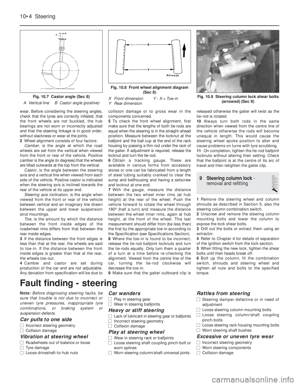
2Wheel alignment consists of four factors:
Camber, is the angle at which the road
wheels are set from the vertical when viewed
from the front or rear of the vehicle. Positive
camber is the angle (in degrees) that the wheels
are tilted outwards at the top from the vertical.
Castor, is the angle between the steering
axis and a vertical line when viewed from each
side of the vehicle. Positive castor is indicated
when the steering axis is inclined towards the
rear of the vehicle at its upper end.
Steering axis inclination, is the angle when
viewed from the front or rear of the vehicle
between vertical and an imaginary line drawn
between the upper and lower suspension
strut mountings.
Toe,is the amount by which the distance
between the front inside edges of the
roadwheel rims differs from that between the
rear inside edges.
3If the distance between the front edges is
less than that at the rear, the wheels are said
to toe-in. If the distance between the front
inside edges is greater than that at the rear,
the wheels toe-out.
4Camber and castor are set during
production of the car and are not adjustable.
Any deviation from specification will be due tocollision damage or to gross wear in the
components concerned.
5To check the front wheel alignment, first
make sure that the lengths of both tie-rods are
equal when the steering is in the straight-ahead
position. Measure between the locknut at the
balljoint and the ball cup at the end of the rack
housing by passing a thin rod under the rack of
the gaiter. If adjustment is required, release the
locknut and turn the tie-rod.
6Obtain a tracking gauge. These are
available in various forms from accessory
stores or one can be fabricated from a length
of steel tubing suitably cranked to clear the
sump and bellhousing and having a setscrew
and locknut at one end.
7With the gauge, measure the distance
between the two wheel inner rims (at hub
height) at the rear of the wheel. Push the
vehicle forward to rotate the wheel through
180º (half a turn) and measure the distance
between the wheel inner rims, again at hub
height, at the front of the wheel. This last
measurement should differ from (be less than)
the first by the appropriate toe-in according to
the Specification (see Specifications Section).
8Where the toe-in is found to be incorrect,
release the tie-rod balljoint locknuts and turn
the tie-rods equally. Only turn them a quarter
of a turn at a time before re-checking the
alignment. Viewed from the centre line of the
car, turning the tie-rod clockwise will
decrease the toe-in.
9Make sure that the gaiter outboard clip isreleased otherwise the gaiter will twist as the
tie-rod is rotated.
10Always turn both rods in the same
direction when viewed from the centre line of
the vehicle otherwise the rods will become
unequal in length. This would cause the
steering wheel spoke position to alter and
cause problems on turns with tyre scrubbing.
11On completion, tighten the tie-rod balljoint
locknuts without altering their setting. Check
that the balljoint is at the centre of its arc of
travel and then retighten the gaiter clip.
9 Steering column lock-
removal and refitting
1
1Remove the steering wheel and column
shrouds as described in Section 5, also the
steering column combination switch.
2Unscrew and remove the steering column
mounting bolts and lower the column to
expose the lock shear bolts.
3Drill out the bolts or extract them using an
extractor.
4Refer to Chapter 4 for details of separation
of the ignition switch from the lock section.
5When fitting the new lock, tighten the shear
bolts until their heads break off.
6Bolt up the column, fit the combination
switch, shrouds and steering wheel and
tighten all nuts and bolts to the specified
torque.
10•4 Steering
Fig. 10.9 Steering column lock shear bolts
(arrowed) (Sec 9)
Fig. 10.8 Front wheel alignment diagram
(Sec 8)
X Front dimension Y - X = Toe-in
Y Rear dimension
Fig. 10.7 Castor angle (Sec 8)
A Vertical line B Castor angle (positive)
Fault finding - steering