1982 VOLVO 960 length
[x] Cancel search: lengthPage 7 of 168

(
70019401960 Specifications
Section
0 General
E
A
c B
132410
Dime ns io n s 7401760 780 944 /964 945/965
mm in mm in mm in mm in
A. Wheelbase .............................. . ...... . 2770 109 2770 109 2770
109 2770 109
B. Overall
length ................................... . 4785 188.4 4794
189 4871 191.8 4844 190.7
C. Overall width .................................... .
1760
69.3
1770 69.7
1750 68.9 1750 68.9
D. Track,
front ..................................... . 14701
) 57.9 1470 57.9 1471 57.9 1471 57.9
rear
................. ..................... . 14602
) 57.5 14602
) 57.5 1460 57.5 1460 57.5
E
. Overall height3
) ...... .........................•.•. 1410 55.5 1400 55.1 1410 55.5 1440 56.7
1) _ Dec. 1984: wheelbase = 1460 mm. 2) 760/960 4-door, 780 1988-Track
rear 1520 mm 59.9 in 3) Depending on type of tyre.
Weight 740
760 780
Approximate weight of car without occupants, fuWfuel tank 1270-1460 kg 1330-1500 kg 1500 kg
(2798-3120Ib) (2930-33051b) (3305 Ib)
944 945 964 965
1327-1463 1363-1496 1484-1576 1438-1527
,-(2924-3223Ib) (3003-3296Ib) (3270-3472lb) (3168-3364Ib)
The weight varies depending on variant and equipment
Fuel tank .................................... .
760/780 -1987,740, standard, 944/945/965 ........... .
increased-capacity
............... .
760 4 -door ., 780 1988-, 964
Litres
60
82
80
US. gal
15.8
21.6
21.1
5
I
Page 18 of 168
70019401960 Specifications
Section 2 B 19, 823 Engines
Group 21 Engine block
Cylinder head
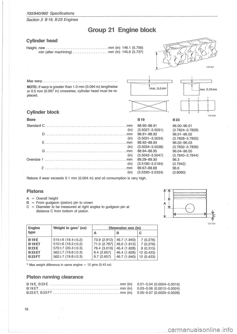
Height, new ................................... mm (in) 146.1 (5.756)
min (after machining)
.................... mm (in) 145.6 (5.737)
Max warp ..
.. ..................................... . .
NOTE: If warp is greater than 1 .0 mm (0.094 in) lengthwise
or 0 .5 mm (0.097 in) crosswise, cylinder head must be re
placed.
Cylinder block
Bore 819 823
Standard C ............................................ .. mm
(in)
D .............................................. mm (in)
E .............................................. mm
(in)
G ........................................... . .. mm
(in)
Oversize 1
...................................... .... .... mm
(in)
2 ..... . -:-......................... ....... ....... mm
(in) 88.9D-88
.
91
(3.5027-3 .5031 )
88 .
91-88.92
(3.5031-3.5034)
88.92 -88.93
(3.5034-3.5038)
88.94-88.95
(3.5042-3.5047)
89 .29-89.30
(3.518D-3 .5184)
89.67-89.68
(3. 533D-3 .5334)
96 .0D-96.01
(3.7824-3. 7828)
96 .01-96.02
(3.7828-3.7832)
96 .02-96.03
(3.7832-3.7836)
96 .04-96.05
(3.7 84D-3 .7844)
96.3
(3.7 942)
96 .6
(3.8060)
Rebore if wear exceeds 0.1 mm (0.004 in) and oil consumption is very high.
Pistons
A = Overall height
8
= From gudgeon (piston) pin to crown
C = Diameter to be measured at right angles to gudgeon pin at
distance
C from bottom of piston.
Engine Weight in gms1 (oz) Dimension mm (in)
type A 8
8 19 E
515±6 (18.4±0.2)
73.9 (2.912) 46.7 (1.840)
8 19
ET 510±6 (18.2±0.2) 71.0 (2.797) 46.0 (1.812)
823E 570±7 (20.4±0.3) 76.4 (3.010) 46.4 (1.828)
823ET 562±7 (19.8 ±0.3) 8.4 (2.657)
46.4 (1.828)
823FT 562±7 (19.8±0.3) 8.7 (2.657)
46.7 (1.840)
1) Max weight difference in same engine = 12 gms (0.43 oz)
Piston running clearance
819 E, 823 E ........................................ mm (in)
819ET .............................................. mm (in)
823 ET, 823 FT ...................................... mm (in)
16
C
7 (0.276)
7 (0.276)
8 (0.315)
12 (0.423)
12 (0.423)
0.01- 0 .04 (0.0004-0.0016)
0 .03- 0.06 (0.0012-0 .0024)
0 .05-0.07 (0.002D-0 .0028)
J
ma x o 25mm
129826
137551
Page 20 of 168
70019401960 Specifications
Section 2 B 19, B 23 Engines
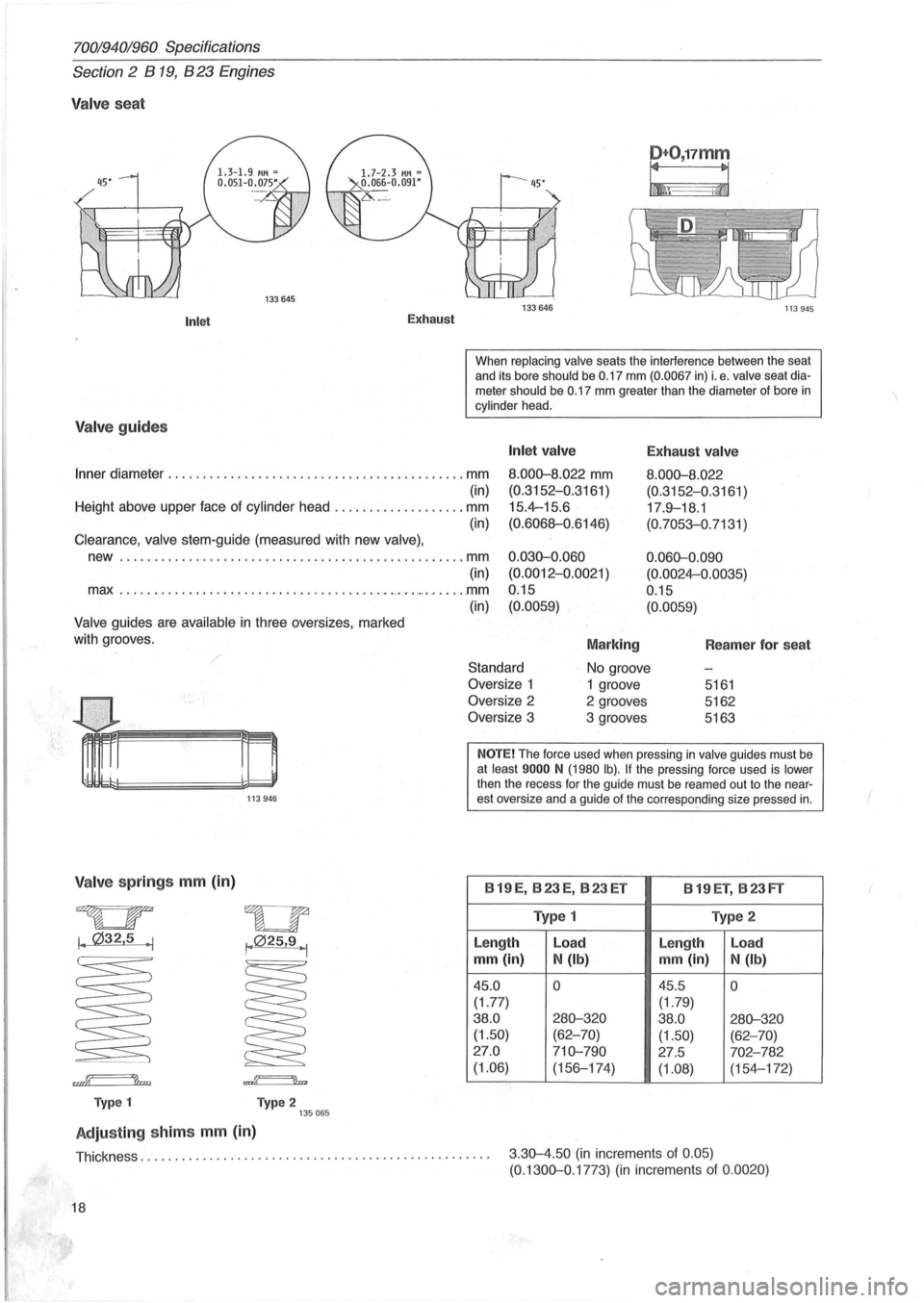
Valve seat
Inlet
Valve guides
Exhaust
D+O,17mm
~\ i~
133646 113945
When replacing valve seats the interference between the seat
and its bore should be 0.17 mm (0.0067 in) i. e . valve seat diameter should be 0.17 mm greater than the diameter of bore in cylinder head.
Inner diameter ........... . ..... ...... ....... ............. mm
Inlet valve
8.000-8.022 mm
(0.3152-0.3161 )
15.4-15.6
(0.6068-0.6146)
Exhaust valve
8.000-8. 022
(0.3152-0.3161 )
17 .
9-18.1
(0.7053-0.7131 )
(in)
Height above upper face of cylinder head ................... mm
(in)
Clearance , valve stem-guide (measured with new valve) ,
new .......... . ...................................... . mm
(in)
max .
................. ................ . ~ .. ,,~ ....... "" ....... mm
(in)
Valve guides are available in three oversizes, marked
with grooves .
0.030-0.060
(0.0012-0.0021
)
0 .15
(0.0059)
Marking
0.060-0.090
(0.0024-0.0035)
0.15
(0.0059)
Reamer for seat
Standard
No groove
V alv e springs mm (in)
~
I. 032,5 . 1
rn~
Typ e 1
113946
wu , .. 025,9 1 I •
..g======'lb
Type 2 135065
Adjusting shim s mm (in)
Oversize 1
1 groove 5161
Oversize 2 2 grooves 5162
Oversize 3 3 grooves 5163
NOTE! The force used when pressing in valve guides must be at least 9000 N (1980 Ib). If the pressing force used is lower
then the recess for the guide must be reamed out to the nearest oversize and a guide of the corresponding size pressed in.
B 19 E, B 23 E, B 23 ET
B 19 ET, B 23 FT
Type 1 Type 2
Length Load
Le
ngth Load
mm (in)
N (Ib) mm (in)
N (Ib)
45.0 0 45.5 0
(1.77)
(1.79)
38.0
280-320 38.0 280-320 (1.50) (62-70)
(1.50) (62-70)
27 .0
710-790 27 .5 702-782
(1.06)
(156-174)
(1.08) (154-172)
Thickness.
. . . . . . . . . . . . . . . . . . . . . . . . . . . . . . . . . . . . . . . . . . . . . . . . . . 3 .30-4.50 (in increments of 0.05) (0. 1300-0.1773) (in increments of 0.0020)
18
Page 22 of 168
70019401960 Specifications
Section 2 B
19, B 23 Engines
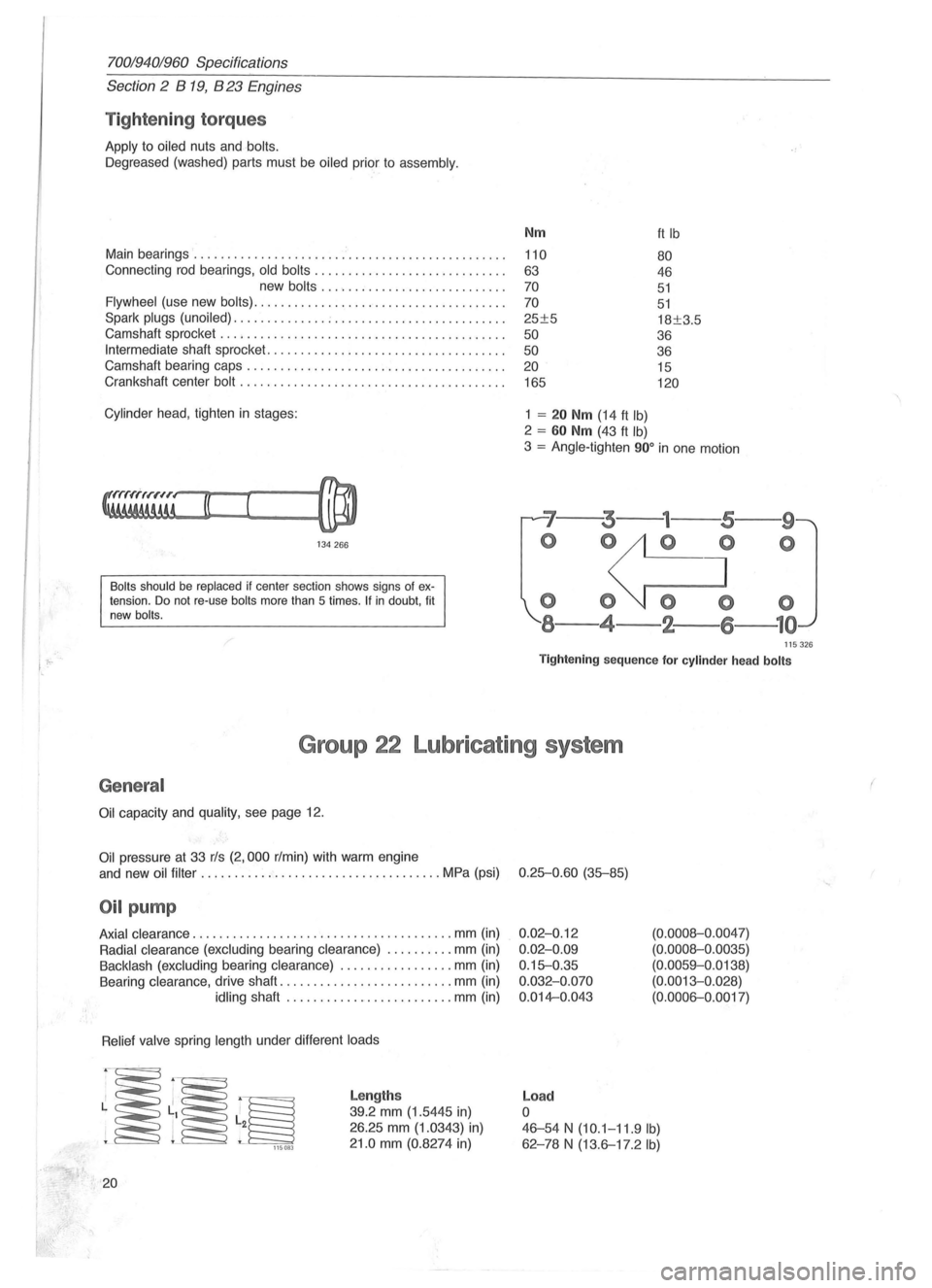
Tightening torques
Apply to oiled nuts and bolts.
Oegreased (washed) parts must be oiled prior to assembly.
Main bearings ....................... ' ....................... .
Connecting rod bearings,
old bolts ............................ .
new
bolts ......... .................. .
Flywheel (use new bolts) ..................................... .
Spark
plugs (unoiled) .............. ; ......................... .
Camshaft sprocket
............... ........................... .
Intermediate shaft sprocket ................................. .. .
Camshaft bearing caps .
............................ ......... .
Crankshaft center
bolt ....................................... .
Cylinder head , tighten in stages:
134266
Bolts should be replaced if center section shows signs of extension. Do not re-use bolts more than 5 times . If in doubt, fit
new bolts.
Nm
110
63
70
70
25±5
50
50 20
165
1 = 20 Nm (14 ft Ib)
2 = 60 Nm (43 ft Ib)
ft Ib
80
46
51
51
18±3.5
36
36 15
120
3 = Angle-tighten 900 in one motion
'7--3---
o 0
000
8-4-2-
--9
o
115326
Tightening sequence for cylinder head bolts
Group 22 Lubricating system
General
Oil capacity and quality, see page 12.
Oil pressure at 33 rls (2,000 r/min) with warm engine
and new
oil filter ...... .............................. MPa (psi) 0.25-0.60 (35-85)
Oil pump
Axial clearance .................. ..................... mm (in)
Radial clearance (excluding bearing clearance) .......... mm (in)
Backlash (excluding bearing clearance) ................. mm (in)
Bearing clearance, drive shaft
.......................... mm (in)
idling shaft ..... ........... .......... mm (in)
Relief valve spring length under different loads
~~~ 115083
20
Lengths
39.2 mm (1.5445 in)
26.25 mm (1.0343) in)
21.0 mm (0.8274 in)
0.02-0.12
0.02-0.09
0.15-0.35
0.032-0.070
0.014-0.043
Load
o
(0.0008-0 .0047)
(0.0008-0.0035)
(0.0059-0.0138)
(0.0013-0. 028)
(0.0006-0.0017)
46-54 N (10.1-11.9 Ib)
62 -78 N (13.6-17.2 Ib)
(
Page 31 of 168
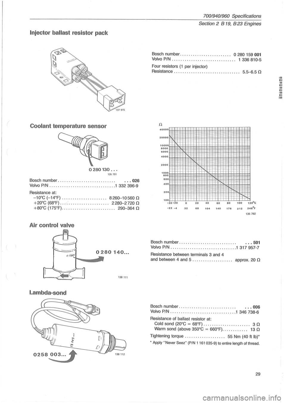
Injector ballast resistor pack
Coolant temperature sensor
0280130 ... 135791
Bosch number. . . . . . . . . . . . . . . . . . . . . . . . . . . . .. 026
Volvo PIN ....................... ........ 1 332 396-9
Resistance
at:
-10°C ( - 14°F) .................... . 8260-10560 n
+20°C (68°F) ....................... 2280-2720 n
+80°C (175 °F) ......................... 290-364 n
A ir control valve
Lambda-sond
0258~3 ... '
70019401960 Specifications
Section
2 B 19, B 23 Engines
Bosch number ...................... " 0 280 159 001
Volvo PIN. . . . . . . . . . . . . . . . . . . . . . . . . . . . .. 1 336 810-5
Four resistors
(1 per injector)
Resistance . . . . . . . . . . . . . . . . . . . . . . . . . . . . .
.. 5.5-6.5 n
40000
20000
10000 8000 6000
4000
2000
1000 800 600 400
200
100
--
il
-30 -20 0 20 40 60 80 100 120°C
-22 -4 32 68 104 140 176 212 248°F
135792
Bosch number. . . . . . . . . . . . . . . . . . . . . . . . . . . . .• 501
Volvo PIN ................. " ..... ....... 1 317957-7
Resistance between terminals 3 and 4
and between 4 and 5 . . . . . . . . . . . . . . . . .
.. approx. 20 n
Bosch number. . . . . . . . . . . . . . . . . . . . . . . . . . . . .. 006
Volvo PIN ............................... 1 346 738-6
Resistance of
ballast resistor at:
Cold sond (20°C = 68°F) . . . . . . . . . . . . . . . . . . . . .. 3 n
Warm sond (above 350°C = 660°F) ............ 13 n
Tightening torque. . . . . . . . . . . . . . . . . .. 55 Nm (40 ft Ib)*
• Apply "Never Seez" (PIN 1161 035-9) to entire length of thread .
29
III
IN III ·11 III
III
III III
Page 33 of 168
70019401960 Specifications
Section 2 B 19, B 23 Engines
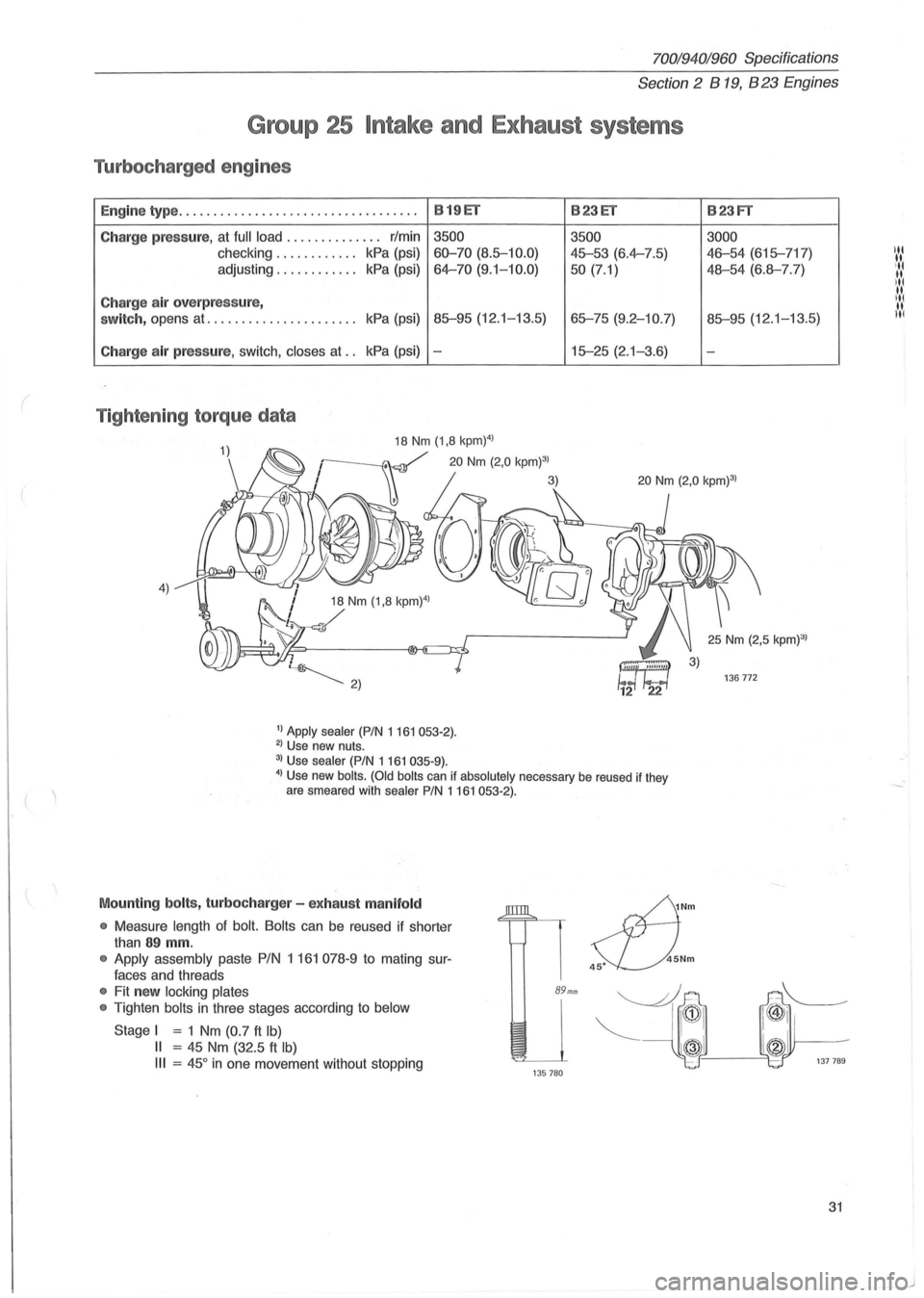
Group 25 Intake and Exhaust systems
Turbocharged engines
En gin e type ................................... B 19ET B23ET
C harge pressure, at full load .............. rlmin 3500
3500
checking ............ kPa (psi) 60-70 (8.5-10.0) 45-53 (6.4-7.5)
adjusting ............ kPa (psi) 64-70 (9. 1-10.0)
50 (7.1)
Charge air overpressure,
switch, opens at ...................... kPa (psi) 85-95 (12.1-13.5) 65-75 (9.2-10.7)
Charge air pressure, switch, closes at .. kPa (psi) -15-25 (2.1-3.6)
Tighten ing torque data
4)
1) Apply sealer (PIN 1161053-2). 2) Use new nuts.
3) Use sealer (PIN 1 161 035-9).
4) Use new bolts . (Old bolts can if absolutely necessary be reused if they
are smeared with sealer PIN 1161053·2).
Mounting bolts, turbocharg er - ex hau st m anifold
•
Measure length of bolt. Bolts can be reused if shorter
than
89 mm.
• Apply assembly paste PIN 1 161 078-9 to mating sur
faces and threads
• Fit new locking plates
•
Tighten bolts in three stages according to below
Stage I = 1 Nm (0.7 ft Ib)
II = 45 Nm (32.5 ft Ib)
III = 45 ° in one movement without stopping
89mm
135780
sfJ
Nm
45Nm 45·
B23FT
3000
46-54 (615-717)
48-54 (6.8-7.7)
85-95 (12.1-13.5)
-
31
Page 39 of 168
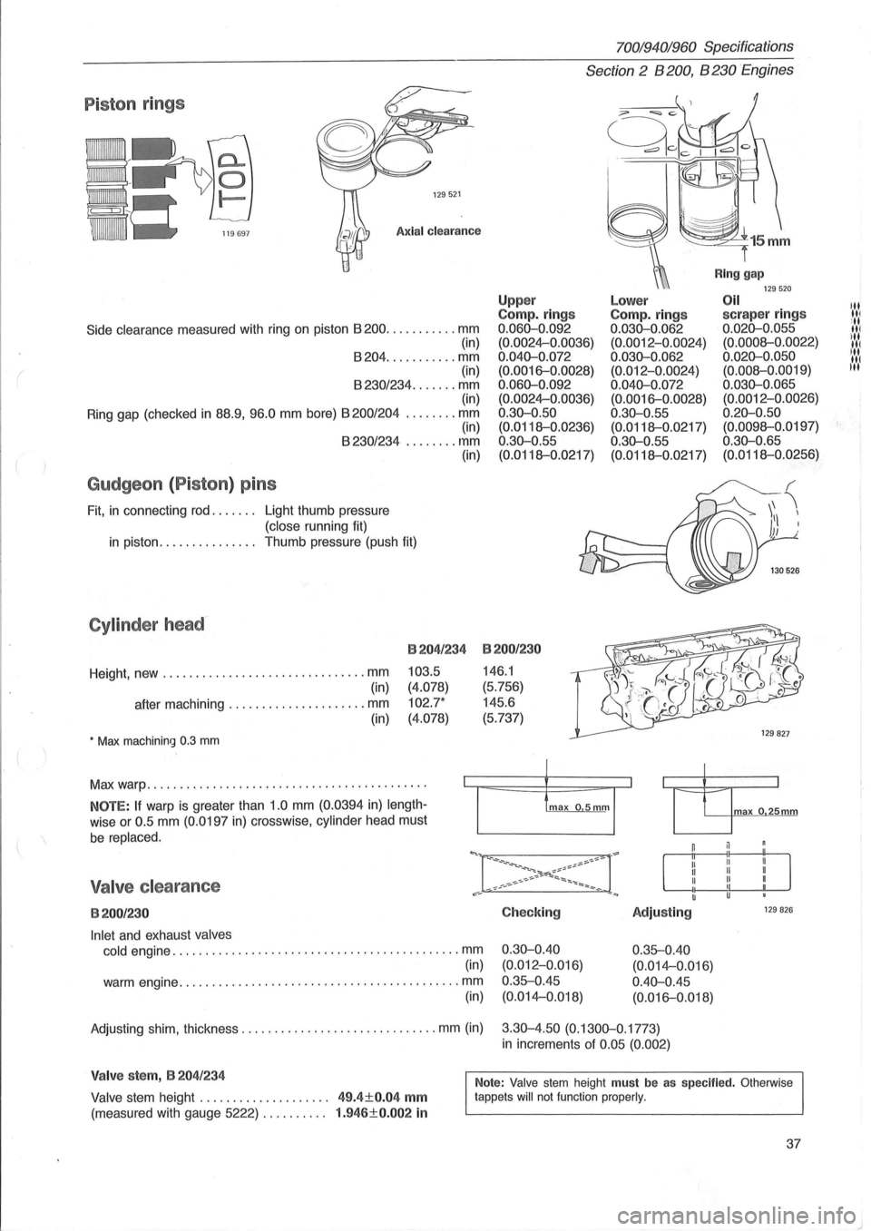
Piston rings
129521
Axial clearance
Side clearance measured with ring on piston 8200 ........... mm
(in)
8204 ........... mm
(in)
8230/234 ....... mm (in)
Ring gap (checked
in 88.9, 96.0 mm bore) 8200/204 ........ mm (in) 8230/234 ........ mm
Gudgeon (Piston) pins
Fit, in connecting rod. . . . . .. Light thumb pressure
(close running fit) (in)
in piston.
. . . . . . . . . . . . .. Thumb pressure (push fit)
Cylinder head-
Height, new ............................... mm
(in)
after machining
..................... mm
(in)
• Max machining 0.3 mm
B204/234
103.5
(4.078)
102.7*
(4.078)
Max warp .......................................... .
NOTE: If warp is greater than 1.0 mm (0.0394 in) length
wise or 0.5 mm (0.0197 in) crosswise, cylinder head must
be replaced.
Valve clearance
B200/230
Inlet and exhaust valves
cold
engine ............................................ mm
(in)
warm engine
........................................... mm
(in)
70019401960 Specifications
Section 2 B 200, B 230 Engines
Upp er Compo rings 0.060-0.092
(0.0024-0.0036)
0.040-0.072 (0.0016-0.0028)
0.060-0.092 (0.0024-0.0036)
0.30-0.50
(0.0118--0.0236)
0.30-0.55
(0.0118--0.0217)
B200/230
146.1
(5.756)
145.6
(5.737)
Checking
0.30-0.40 (0.012-0.Q16)
0.35--0.45 (0.014-0.018)
Lower Compo rings 0.030-0.062 (0.0012-0.0024)
0.030-0.062 (0.012-0.0024)
0.040-0.072 (0.0016-0.0028)
0 .30-0.55
(0.0118--0.0217)
0.30-0.55
(0.0118--0.0217)
Adjusting
0.35--0.40
(0.014-0.016)
0.40-0.45 (0.016-0.018)
Ring gap 129520 Oil scraper rings 0.020-0.055
(0.0008--0.0022)
0.020-0.050 (0.008--0.0019)
0.030-0.065 (0.0012-0.0026)
0.20-0.50 (0.0098--0.0197)
0.30-0.65 (0.0118--0.0256)
max o 25mm
129 826
Adjusting shim, thickness .............................. mm (in) 3.30-4.50 (0.1300-0.1773)
in increments of 0.05 (0.002)
Valve stem, B 204/234
Valve stem height . . . . . . . . . . . . . . . . . . .. 49.4±0.04 mm
(measured with gauge 5222) . . . . . . . . .. 1.946±0.002 in
Note: Valve stem height must be as specified. Otherwise
tappets will not function properly.
37
III III
ill III ill
IN liN
t·
Page 42 of 168
70019401960 Specifications
Section 2 B 200, B 230 Engines
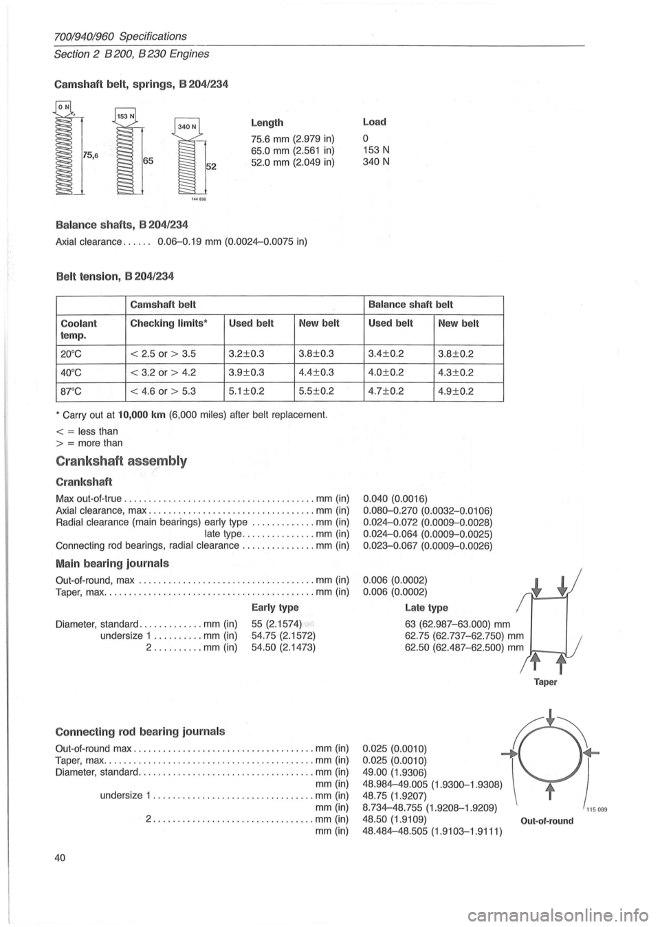
Camshaft belt, sp ring s, B 204/234
144B!Hi
Balanc e shaf ts , B 204 /234
Length
75.6 mm (2.979 in)
65.0 mm (2.561 in)
52.0 mm (2.049 in)
Axial clearance. . . . .. 0.06-0.19 mm (0.0024-0.0075 in)
Belt tension, B 204/ 234
Camshaft belt
Coolant
Checking limits ' Used belt New belt
temp.
20°C < 2 .5 or > 3.5 3.2±0.3 3.8±0.3
40°C < 3.2 or > 4.2 3.9±0.3 4.4±0.3
8rC < 4.6 or > 5.3 5
.1 ±0.2 5 .5±0.2
• Carry out at 10,000 km (6,000 miles) after belt replacement.
< = less than
> = more than
Crankshaft assembly ,/
Cranksh aft
Max out-at -true .................................. ..... mm (in)
Axial clearance, max .................................. mm (in)
Radial clearance (main bearings) early type ............. mm (in)
late type ............... mm (in)
Connecting rod bearings, radial clearance ............... mm (in)
Main bearing journals
Out-at-round , max ................................ .... mm (in)
Taper, max
........................................... mm (in)
Early type
Diameter , standard ............. mm (in) 55 (2.1574)
54.75 (2.1572)
54.50 (2. 1473)
undersize
1
.......... mm (in)
2 .......... mm (in)
Connecting rod bearing journa ls
Out-at-round max ..................................... mm (in)
Taper, max .
.......................................... mm (in)
Diameter, standard .
............ , ...................... mm (in)
mm (in)
40
undersize 1 ................................. mm (in)
mm (in)
2 ................. ................ mm (in)
mm (in)
Load
o
153 N
340 N
Balance shaft belt
Used belt New belt
3.4±0.2 3.8±0.2
4.0±0.2 4.3±0.2
4.7±0.2 4.9±0.2
0 .040 (0.0016)
0.080-0 .270 (0.0032-0.0106)
0 .
024-0.072 (0.0009--0 .0028)
0.024-0.064 (0.0009--0.0025)
0.023-0.067
(0. 0009--0.0026)
0.006 (0.0002)
0.006 (0.0002)
Late type
63 (62.987-63 .000) mm
62.75 (62.737-62.750) mm
62.50 (62.487-62.500) mm
t
Taper
0.025(0.0010) f ~
0.025 (0.0010) ) 49.00 (1.9306)
48.984-49.005
(1.9300-1.9308)
48.75 (1.9207)
8.734-48.755 (1.9208-1.9209)
115 089
48.50 (1.9109) Out-ot-round
48.484-48.505 (1.9103-1.9111)