1982 VOLVO 960 clutch
[x] Cancel search: clutchPage 9 of 168
(
Carburettor
Fuel pump
Clutch
Alternator ,
Steering box
SU
Pierburg
Solex Pierburg
Bosch
AC- oelco
Sofabex
Fichtel & Sachs
Verto/Valeo
Bosch
Cam Gear
Zahnrad Fabrik (ZF)
~
'?' .'" ... .
.
---
" .. u.·.. ,
2
3
5
2
3
4
5
2
3
1
2
3
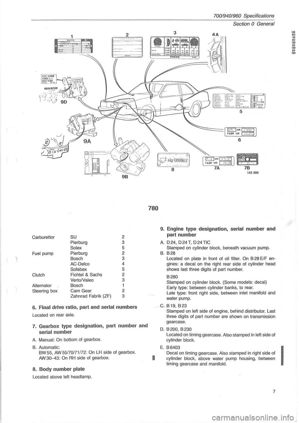
6 . Fina l drive ratio , part and seria l numbers
Located on rear axle .
7. Gearbox type des ig nation, part numbe r and
serial num ber
A. Manual : On bottom of gearbox .
B. Automatic:
BW 55,
AW 55/70171 /72: On LH side of gearbox.
AW3Q-43:
On RH side of gearbox.
8 . Body number pla te
Located above left head lamp.
780
70019401960 Specifications
Section
0 General
3
6
8
7 B 143980
9. Engine type des ig nation, serial number an d
part number
A. 024, o24T, o24TIC
Stamped on cylinder block, beneath vacuum pump.
B. B28
Located on plate in front of oil filter . On B 28 ElF en
gines: a
decal on the right rear side of cylinder head
shows
last three digits of part number.
B280
Stamped on cylinder block. (Some models: decal)
Early
type : between cylinder banks, to rear.
Late type: front right side, between
inlet manifold and
water pump.
__ -G.-819, B 23
I
Stamped on left side of engine, behind distributor. Last
three digits of part number are shown
on transmission
gearcase.
O. B 200, B 230
Located on timing gearcase . Also stamped in left side of
cylinder block.
E. B6403
Decal
on timing gearcase. Also stamped in right side of
cylinder block, above water pump housing , between
timing gearcase and
manifold.
7
I
J
Page 137 of 168
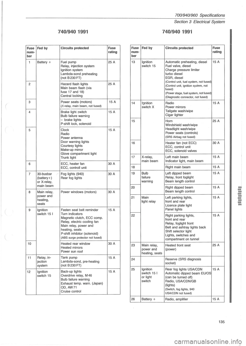
740/940 1991
Fuse Fed
by Circuits
protected Fuse Fuse
num- rating num-
ber ber
1
Battery + Fuel pump 25 A 13 Relay, injection
system Ignition system
Lambda-sond preheating
(not B
230 FT) f-----2 Hazard flash
lights 25 A
Main beam flash (via
fuse 17 and 18)
Central locking f-----
( 3 Power seats (motors) 15 A (X-relay, main beam , not fused) 14
r----4 Brake lighi switch
15 A Bulb failure warning
- brake lights f-----15 P-shift lock, solenoid f-----5 Clock 15 A
Radio
Power antenna -Door warning lights 16
Courtesy lights Make-up mirror Glove compartment light Trunk light 17 f-----6 ECC,
heater fan 30 A
-
ECC, controll unit 18
7 30-busbar
Fog
lights (940) 30 A 19
(battery+ ) Rear fog lights or X-relay, main beam -20
8 Main relay, Power windows
(motors) 30 A
power and
heating,
21
seats
9
Ignition Fasten seat belt reminder 15 A
switch 15 I Turn indicators
Magnetic clutch, ECC comp o
-
22
Relay, electric cooling fan Main relay, power and
heating, seats
P-shift inhibitor (solenoid) (ABS surge protector not fused) I----(
10 Heated rear window 30 A
Heated mirrors 23
Power sun
roof
11 Relay , in- Tank pump
15 A
jection Lambda-sond,
pre-heating 24
system (not
B
230 FT)
12
Ignition Back-up lights 15 A 25
switch 15 Overdrive relay, M
46 Bulb failure warning
Exhaust temp. warn. (Japan)
OD, AW71
Cruise control
26
Fed by
Ignition switch 15
Ignition
switch X
X-relay, main beam
Bulb
failure
warning
Main
light relay
Main relay, power and
heating, seats
Ignition switch 15 I or light switch
Battery +
70019401960 Specifications
Section 3 Electrical System
740/940 199 1
Circuits protected Fuse
rating
Automatic preheating, diesel 15 A Fuel valve, diesel Charge pressure limiter turbo diesel EGR, diesel (Control unit, fuel system, not fused) (Control unit, ignition system, not
fused)
(Power stage , fuel system, not fused)
(Diagnostic connector, not fused)
Radio 15
A Power mirrors
Tailgate wash/wipe
Cigar
lighter
Horn 25
A Windshield wash/wipe Headlight wash/wipe Power seats (controls) (SRS Airbag not fused)
Heater fan (not ECC) 30 A
ECC , control unit
ECC, solenoid valves
Left main beam 15
A Indicator light, main beam
Right main beam 15
A
Left dipped beam 15
A
Relay, front foglight Beam length control
Right dipped beam 15
A
Beam length control
Left parking lights, 15 A
front and rear
Licence
plate light
Panel lights
Right parking lights, 15 A
front and rear
Relay, foglight front Belt and ashtray lights back
Shift selector light Lights, switches and
compartment on tunnel
Heated front seat 25
A
(power)
Reserve
(SRS diagnosis
socket)
Rear
fog lights USA/CDN 15 A
Automatic dipped beam EU/OS (can be turned off)
Radio, USA/CDN/GB
(lights) (Switch, fog lights, 940 USNCDN not fused)
Radio, amplifier 15 A
135
I
Itl Itll
,It I Iltl ·ltl 1111 III
'", II.
Page 140 of 168
70019401960 Specifications
Section
4 Power Transmission
Section 4 Power Transmission
Group 41 Clutch ...... . . . . . . . . . . . . . . . . . . . . . . . .. 138
Group 43
Manual transmission. . . . . . . . . . . . . . . . . .. 138
Group 43 Automatic transmission BW 55 . . . . . . . . . .
140 AW70171/72 ..... 142
AW 30-43 LE. . .. 146
ZF 4HP 22 ...... 149
Group 45
Universal joint. . . . . . . . . . . . . . . . . . . . . . . .. 151
Group 46 Rear axle ............................. 151
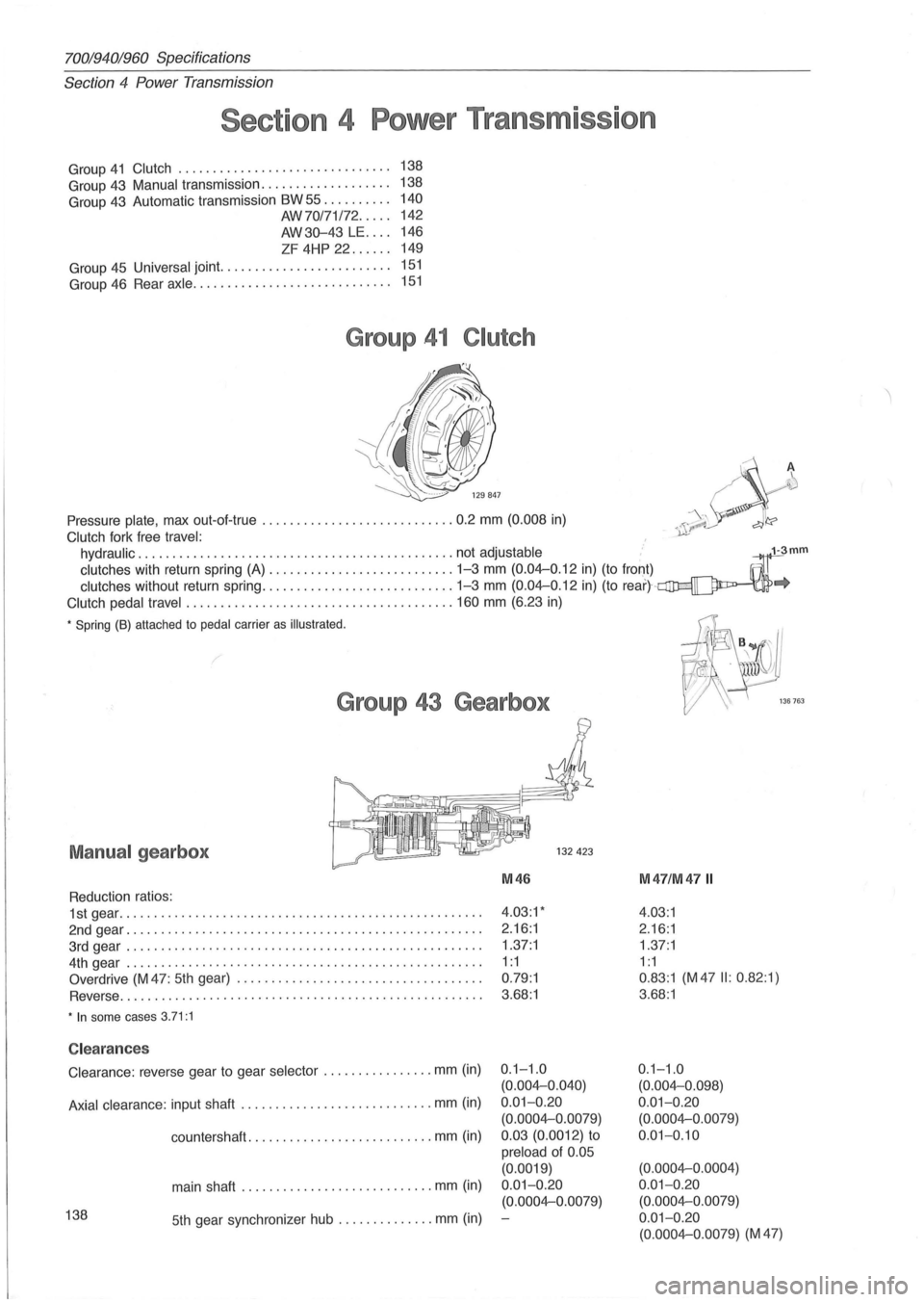
Group 41 Clutch
~
~" A ~
-\ . 'I Pressure plate, max out-of-true ............................ 0.2 mm (0.008 in) /\'~\ dl'?
Clutch fork free travel: , ~-
hydraulic ... ", ........................................ not adjustable ... ~mm
clutches w!th return spring. (A) ............... , ........... 1:3 mm (0.04-0.12 !n) (to fro!:),t) . ~ . IllJ
clutches without return sprlng ............................ 1 3 mm (0.04-0.12 In) (to rear)-~"
Clutch pedal travel ............ ........................... 160 mm (6.23 in)
• Spring (8) attached to pedal carrier as illustrated . 1
-if. B .. ru~'
Group 43 Gearbox
Manual gearbox
Reduction ratios:
1st gear
................................................... , .
2nd gear .
............................... ................... .
3rd gear
................................................... .
4th gear
......................... ........... ............... .
Overdrive
(M 47 : 5th gear) ................................... .
Reverse ..
.......................................... ........ .
• In some cases 3.71:1
Clearances
Clearance: reverse gear to gear selector ................ mm (in)
Axial clearance : input shaft ............................ mm (in)
countershaft.
........... ............... mm (in)
main shaft ............................ mm (in)
138 5th gear synchronizer hub .............. mm (in)
M46
4.03:1'
2.16 :1
1.37 :1
1
:1
0.79 :1
3 .
68:1
0.1-1 .0
(0.004-0.040)
0.01-0 .20
(0.0004-0.0079)
0.03 (0.0012)
to
preload of 0.05
(0.0019)
0.01-0 .
20
(0.0004-0 .0079)
I@ ' " '..,,~ W 7 '\. /_-
\ 136763
M47/M47 II
4 .03:1
2 .16 :1
1 .
37:1
1: 1
0 .83:1 (M 47 II: 0.82 :1)
3.68:1
0 .1-1.0
(0.004-0.098)
0 .
01-0.20
(0.0004-0 .0079)
0 .01-0.10
(0.0004-0 .0004)
0.01-0.20 (0.0004-0.0079)
0 .
01- 0.20
(0.0004-0.0079) (M 47)
Page 142 of 168
70019401960 Specifications
Section 4 Power Transmission
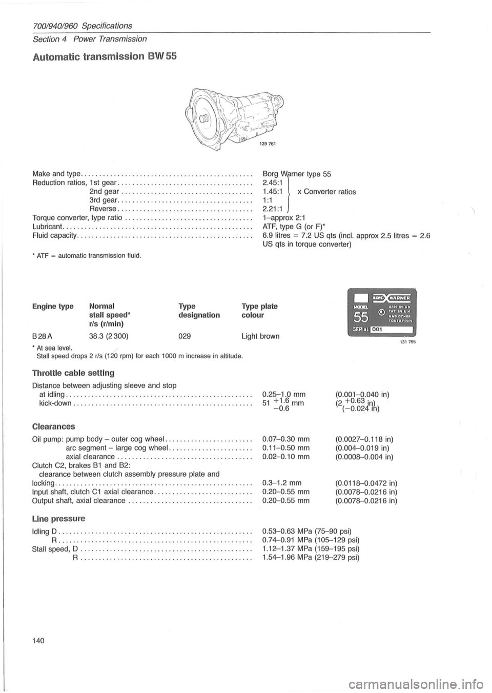
Automat ic transmission BW 55
Make and type .. ............................................ .
Reduction ratios, 1 st gear ..
................. ................. .
2nd gear
................................... .
3rd gear
................... ................. .
Reverse
.................................... .
Torque converter, type ratio
................................ .. .
Lubricant.
........................... ....................... .
Fluid capacity .................... ........................... .
* ATF = automatic transmission fluid.
1.45:1 x Converter ratios
Borg
Wirner type
55
2.45 :1
1 : 1
2.21 : 1
1-approx 2:1
ATF, type G (or F)*
6.9
litres = 7.2 US qts (inc!. approx 2.5 litres = 2 .6
US qts in torque converter)
.~ Engine type Normal
stall speed*
rls (r/min)
Type
designation
Type plate
colour
....... WAOIIHUH
55 e:> ~~D ~~~I~ f'"OUTUTAUS
B28A 38.3 (2300) 029 SERIAl~ Light brown 131755 * At sea level.
Stall speed drops 2 rls (120 rpm) for each 1000 m increase in altitude .
Throttle cable setting
Distance between adjusting sleeve and stop
at idling .................................................. .
kick -down
........................ ........................ .
C leara nces
Oil pump: pump body -outer cog wheel ....................... .
arc segment -
large cog wheel ...................... .
axial clearance .................................... .
Clutch C2, brakes B1 and B2:
clearance between
clutch assembly pressure plate and
locking ..................................................... .
Input shaft, clutch C1 axial clearance .......................... .
Output shaft,
axial clearance ................................. .
Line pressure
Idling D .................................................... .
R ..................... .... ........................... .
Stall speed, D .................. .............. ...... ........ .
R .............................................. .
140 0.25-1
.0
mm 51 +1.6mm -0.6
0.07-0.30 mm
0.11-0 .50 mm
0.02-0.10 mm
0.3-1 .2 mm
0.20-0 .55 mm
0.20-0.55 mm
(0.001-0.040 in) (2 +0.63 in) (-0.024Ih)
(0.0027-0.118 in)
(0.004-0 .019 in)
(0.0008-0.004 in)
(0.0118-0 .0472 in)
(0.0078-0.0216 in)
(0.0078-0.0216 in)
0.53-0.63 MPa (75-90 psi)
0.74-0.91 MPa (105-129 psi)
1 .12 -1.37
MPa (159-195 psi)
1.54-1.96
MPa (219-279 psi)
Page 145 of 168
(
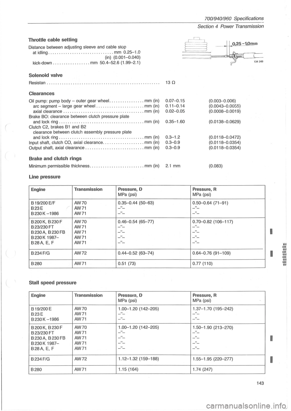
Throttl e cable se tting
Distance between adjusting sleeve and cable stop
at idling .............................. mm 0.25-i.O
(in) (0. 001-0.040)
kick-down ............. .... mm 50.4-52.6 (1.99-2.1)
Sol e n o id va lv e
Resistan . . . . . . . . . . . . . . . . . . . . . . . . . . . . . . . . . . . . . . . . . . . . . . . . . . . . 13 0
C lea ra n ces
Oil pump : pump body -outer gear wheel. ............... mm (in)
arc segment -large gear wheel ...................... mm (in)
axial clearance ................................ ..... mm (in)
Brake BO: clearance between clutch pressure plate
and lock ring ....................................... mm (in)
Clutch C2, brakes B1 and B2
clearance between clutch assembly pressure plate
and lock ring ....................................... mm (in)
Input shaft, clutch CO, axial clearance ........... ... ..... mm (in)
Output shaft, axial clearance ................. .......... mm (in)
B ra ke a nd clutch ring s
0.07-0.15
0 .
11-0.14
0 .
02-0.05
0.35-1.60
0.3--1.2
0 .
3--0.9
0.3--0 .9
Minimum permissible thickness ..................... .... mm (in) 2.1 mm
Line pr ess ure
Engine Tra nsmi ssion Press ure, 0
MPa (psi)
B
19/200 ElF AW70 0.35-0.44
(50--63)
B23E AW71 "
B230K -1986 AW71 "
B200K, B230F AW70 0.46-0.54 (65-77)
B23/230FT AW71 "
B 230 A
, B 230 FB AW71 "
B230K 1987-AW71 "
B28A, E, F AW71 "
B234 FIG AW72 0.44-0
.52 (63--74)
B280
AW71 0.51 (73)
S tall spee d press ure
Engine T
ra n smi ssion Press ure, 0
MPa (psi)
B
19/200 E AW70 1.00--1.20 (142-205)
B23E AW71 "
B230K -1986 AW71 "
B 200 K, B 230 F AW70 1.00--1.20 (142-205)
B23/230 FT AW71 "
B 230 A, B 230 FB AW71 "
B230K 1987-AW71 "
B28A, E, F AW71 "
B234 FIG AW72 1.12
-1.32 (159-188)
B280 AW71 1
.15 (164)
7001940 1960 Specifications
Section
4 Power Transmission
025-10mm
(0.003 -0 .006)
(0.0043--0 .0055)
(0.0008-0.0019)
(0.0138-0.0629)
(0.0118-0.0472)
(0.0118-0.0354)
(0.0118-0 .0354)
(0.083)
Pres sur e, R
MPa (psi)
0.50--0 .64 (71-91)
"
"
0.70--0.82 (106-117)
"
"
"
"
0.64-0.76 (91-109)
0 .
77 (110)
Press ure, R
MPa (psi)
1.37-1.70 (195-242) "
"
1.50--1.90 (213-270)
- -
"
"
"
1 .55-1.95 (220--277)
1 .
74 (247)
-
143
I
I
I
I
Page 163 of 168
(
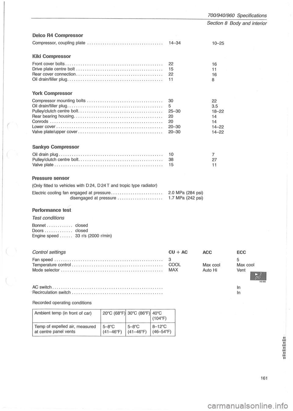
Delco R4 Compressor
Compressor, coupling plate ................................... 14-34
Kiki Compressor
Front cover bolts. . . . . . . . . . . . . . . . . . . . . . . . . . . . . . . . . . . . . . . . . . . . . 22
Drive
plate centre bolt . . . . . . . . . . . . . . . . . . . . . . . . . . . . . . . . . . . . . . . . 15
Rear cover connection. . . . . . . . . . . . . . . . . . . . . . . . . . . . . . . . . . . . . . . .
22
Oil drain/filler plug. . . . . . . . . . . . . . . . . . . . . . . . . . . . . . . . . . . . . . . . . . . . 11
York Compressor
Compressor mounting bolts ........................ .......... .
Oil drain/filler plug ........................................... .
Pulley/clutch centre bolt. ..................................... .
Rear bearing housing
.................................. ...... .
Con rods .
.................................................. .
Lower cover
........................................ .. ...... .
Valve plate/upper cover ...................................... .
Sankyo Compressor
30
5
25-30
20
20
20-30
20-30
Oil drain plug. . . . . . . . . . . . . . . . . . . . . . . . . . . . . . . . . . . . . . . . . . . . . . . . 10
Pulley/clutch
centre bolt. . . . . . . . . . . . . . . . . . . . . . . . . . . . . . . . . . . . . . . 38
Valve plate. . . . . . . . . . . . . . . . . . . . . . . . . . . . . . . . . . . . . . . . . . . . . . . . . . 15
Pressure sensor
(Only fitted to vehicles with D 24, D 24 T and tropic type radiator)
70019401960 Specifications
Section 8 Body and interior
10-25
16
11
16
8
22
3.5
18-22
14
14
14-22
14-22
7
27
11
Electric cooling fan engaged at pressure ....................... .
disengaged at pressure
.................... .
2.0 MPa (284 psi)
1 .7 MPa (242 psi)
Performance test
Test conditions
Bonnet . . . . . . . . . . .. closed
Doors . . . . . . . . . . . .. closed
Engine
speed. . . . .. 33 r/s (2000 r/min)
Control settings
Fan speed ........................... ...................... .
Temperature
control . ................................. ....... .
Mode
selector . ............................................. .
AC switch ............. ..................................... .
.
Recirculation switch ......................................... .
Recorded operating conditions
Ambient temp
(in front of car) 20°C (68°F) 30°C (86°F)
40°C
(104 °
F)
Temp of expelled air, measured 5-8°C 5-8°C 8-12°C
CU + AC
3
COOL
MAX
at centre panel vents
(41-46°F) (41-46 °F) (46-54°F)
ACC
Max cool
Auto Hi
ECC
5
Max cool
Vent
-In
In
143985
161
·11 lit ·11 lit ·11 lit ·11 III II