1982 VOLVO 960 suspension
[x] Cancel search: suspensionPage 3 of 168
(
)
Contents
General
Lubrication B 19, B 23 Engines
B200, B230, B204, B234 Engines
B28 Engine
B280 Engine
B
6304 Engine
024, 024 T , 024 TIC Engines
Electrical System
Power Transmission
Brakes
Suspension and steering
Springs , dampers and
wheels
Body and interior
Revisions and changes to the previous edition are indicated by
a
line in the margin.
Order No. TP 30518/10
Supersedes TP 30518/9
70019401960 Specifications
'., ..
SAN DIEGO ~OLVO
tI5384
2
12
15
35
69 86
98
108
118
138
153 155
159
160
We reserve the right to make alterations without prior notification.
11111 1 1111 1111 IIII! 1111
11111 1111 1111 ·1111 1111 11111 1111 11111 1111 11111 1111 1111 1111
;::::::: 1111 1,1 ..... 1111 II,' ....
~:,:,:,: 1111 , ...... 1
1,' .... 1
1 ...... 1 1111 ·11" 1111 ,II', 1111 III'
I:':':':
'"' '"' ~ .... ,'. 1111 , .... " 1 III' 1111
:I:':',~ ·11 11,1
,"' 1111 III'
'" 1111 ...... 1 ,11' "'1 ,II'
"" I .... I~ III
"' "' ·111 1111 ,III
"' I II I
'" 1111
"' 1111
·11' 1111 I II 1 III III 11 .... 1 III 111/ ,II til. '"I III 1111 .'.'111 ,III 111/ ,II
11.'.'1
Itt'.'1
' llt
lit 'II It.'I'1 It.'.'1 III IItl 'II~ III III til "'1 " " , .... 11
'~I~'~
Page 8 of 168
I
70019401960 Specifications
Section 0 General
1
~-
'''''~''''.' .. ~. . . , .... -. . .~. ," _. , . ..... ,. . . . . VOLV o . '
VOLVO _._N
C I, c , ,. .. , . I
4 C 3
r--8280 9A 150 873
740,760 ,940 ,960
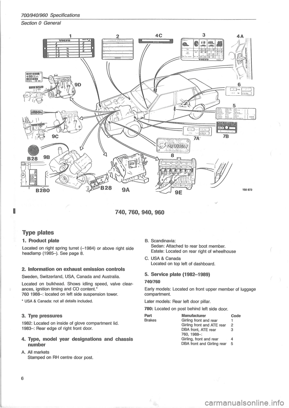
T ype p lates
1. P roduc t p la te
Located on right spring turret (-1984) or above right side
headlamp (1985-). See page 8.
2 . Inf ormation on exhau st emissio n co ntr ols
Sweden , Switzerland, USA, Canada and Australia.
Located on bulkhead. Shows idling speed, valve clear
ances, ignition timing and CO content. '
760 1988-: located on left side suspension tower.
* USA & Canada: not all details included .
3. Tyre p ress ures
1982 : Located on inside of glove compartment lid.
1983-: Rear edge of right front door.
4. Type, m ode l year des ig nat io ns a nd c hass is
numbe r
A. All markets
Stamped
on RH centre door post.
6
B. Scandinavia:
Sedan: Attached to rear boot member .
Estate: Located on rear right of
wheelhouse
C. USA & Canada
Located on top
left of dashboard.
5. Service pla te (1982-1 989 )
74 01760
Early models : Located on front upper member of luggage
compartment.
Later
models: Rear left door pillar.
780: Located on post behind left side door.
Part Brakes Manufactur er Girling front and rear Girling front and ATE rear
DBA front, ATE rear 760,1988-:
Code 1 2 3
Girling, front and rear 4
DBA front and Girling rear 5
(
Page 157 of 168
(
70019401960 Specifications
Section
6 Suspension and steering
Section 6 Front end and steering
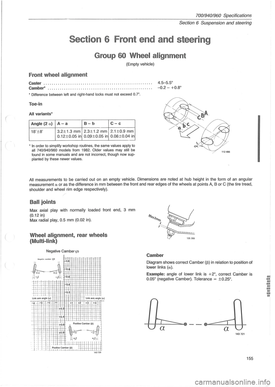
Group 60 Wheel alignment
(Empty vehicle)
Front wheel alignment
Caster ..................................................... 4.5-5.5°
Cambe r*
... ................................... ........ ..... -0.2 -+0.8 °
• Difference between left and right-hand locks must not exceed o.r.
Toe-in
All variant s*
Angle (2 (X) A-a 8-b C-c
18'±8' 3.2±1
.3 mm 2.3±1.2 mm 2 .1 ±0.9 mm
0 .12±0.05 in 0.0 .9±0.05 in 0.08±0.04 in .-
• In order to simplify workshop routines, the same values apply to all 740/940/960 models from 1982. Older values may still be
found in some manuals and are not incorrect, though now supplanted by these newer values.
All measurements to be carried out on an empty vehicle. Dimensions are noted at hub height in the form of an angular
measurement a or as the difference in mm between the front and rear edges of the wheels at points A, B or C (the tire tread,
shoulder and wheel rim edge respective ly).
Ball joints
Max axial play with normally loaded front end, 3 mm
(0.12 in)
Max radial play, 0.5 mm (0.02 in).
Wheel alignment, rear wheels
(
Multi -link )
Negative Camber IfJl
'legall. umb .. 113' -1.0
;l
+
a +a ~ -0.
r;-~ -0.6
P--I I
ii I-i . IT -'. ! . -.1-Un k arm angle (n)
-0
-0
.
Un k a~ angle (a)
-4 -'.-3 "';-2 1 +i +2 + +4 1-
-~~ u ~ 1"'--H---. 1-i-J:-L
_. f-L -\-;-_1_ i-'-1.L?.4 h-
"Lllft~~~~
L.l. f:l+ ~:; +fJ~ .
: I : . : . ill I I I I I m t I " " "! i _ J . ,. . I Positive Camber I~) H 1-1 I I II II ~ t ,I. L LLLu....L1 143 720
Camber
Diagram shows correct Camber (fj) in relation to position of
lower links (a).
Examp le: angle of lower link is +2°, correct Camber is
0 .05 ° (negative Camber). Tolerance = ±0.25°.
143721
155
·ltl III ·ltl It •. ·ltl III ·ltl 'It ·It '
Page 158 of 168
70019401960 Specifications
Section
6 Suspension and steering
A
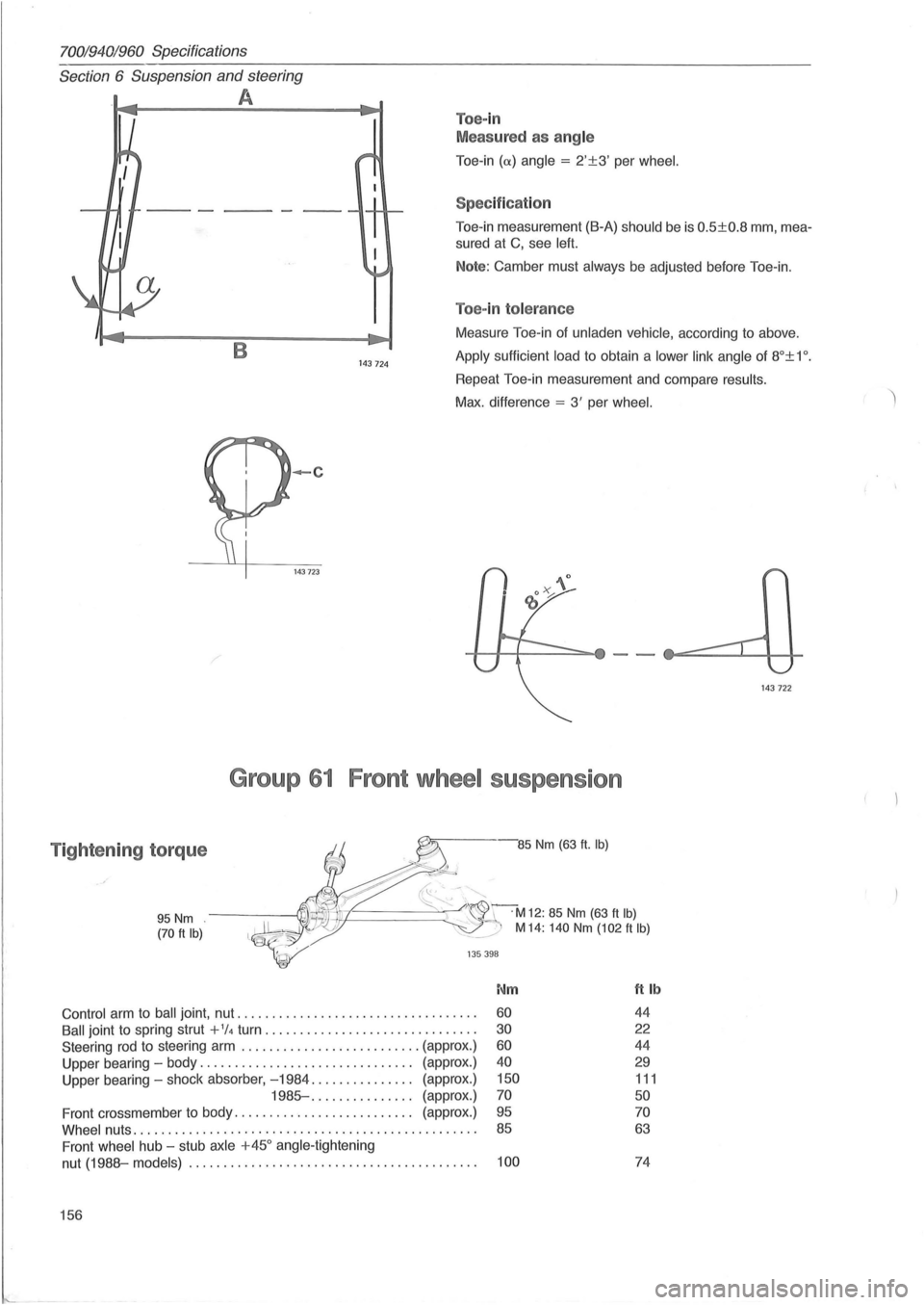
Toe-in
Meas ured as ang le
Toe -in (
Toe-in measurement (B-A) should be is 0.5±0.8 mm, mea
sured at C, see left.
Note: Camber must always be adjusted before Toe-in.
Toe-in tolerance
B 143 724
Measure Toe-in of unladen vehicle, according to above .
Apply sufficient load to obtain a lower link angle of 8°± 1 o .
Repeat Toe-in measurement and compare results.
Max. difference = 3' per wheel.
-c
143723
Group 61 Front wheel suspension
Tightening torque -85 Nm (63 ft. Ib)
95 Nm (70 ft Ib)
~~-.'"
~~======~~C r~M12: 85 Nm (63 ft Ib) ~:./ M 14: 140 Nm (102 ft Ib)
135 398
Nm ft Ib
Control arm to ball joint , nut .................................. . 60 44
Ball joint to spring strut + 1/4 turn .............. ................ . 30 22
Steering rod to steering arm .......................... (approx.) 60 44
Upper bearing -body ............................... (approx.) 40 29
Upper bearing -shock absorber, -1984 ............... (approx .) 150 111
1985- .... ........... (approx.) 70 50
Front crossmember to body. . . . . . . . . . . . . . . . . . . . . . . . . . (approx.) 95 70
Whee l nuts ......... .. ................................ .. ... . . 85 63
Front wheel hub -stub axle +450 angle -tightening
nut
(1988-models) ................................. . ....... . 100 74
156
143 722
Page 159 of 168
(
70019401960 Specifications
Section 6 Suspension and steering
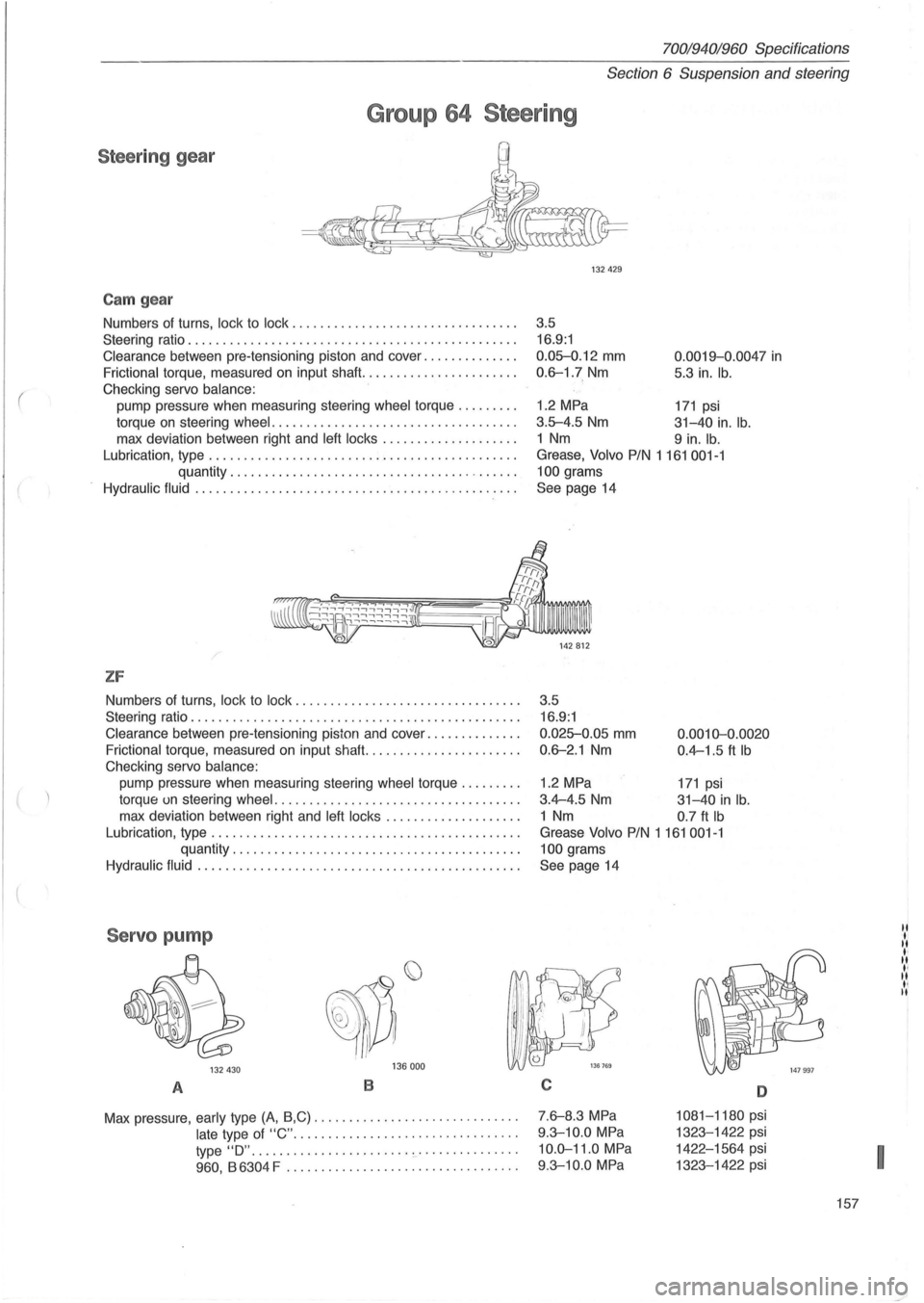
Group 64 Steering
Steeri ng gear
Cam gear
Numbers of turns, lock to lock ...................... .......... .
Steering ratio .
.............................................. .
Clearance between pre-tensioning piston and cover ............. .
Frictional torque, measured on input shaft ...................... .
Checking servo
balance:
pump pressure when measuring steering wheel torque ........ .
torque
on steering wheel . ............................. ..... .
max deviation between right and
left locks ................... .
Lubrication, type
............................................ .
quantity .
........................................ .
Hydraulic fluid ..... .... ..................................... .
/
ZF
Numbers of turns, lock to lock ................................ .
Steering ratio
............................................... .
Clearance between pre-tensioning piston and cover ............. .
Frictional torque, measured on input shafl. ..................... .
Checking servo
balance:
pump pressure when measuring steering wheel torque ........ .
torque un steering
wheel ................................... .
max deviation between right and
left locks ................... .
Lubrication, type
............................................ .
quantity
........................... .............. .
Hydraulic fluid .............................................. .
Servo pump
132 430 136 000
A B
Max
pressure, early type (A, B,C) ............................ . .
late type of "C" ....... .... ..................... .
type
"0" ................... .... 0-' .•• •••••.••...
960 , B 6304 F ................................. .
132429
3 .5
16.9:1
0.0~.12 mm
0.6-1.7 Nm
0 .0019-0.0047 in
5.3 in. lb.
1.2 MPa 171 psi
3 .5-4.5 Nm 31-40 in. lb.
1 Nm 9 in. lb.
Grease, Volvo PIN 1161001-1
100
grams
See page 14
3.5 16.9:1
0.025-0.05 mm
0.6-2.1 Nm
0.0010-0.0020
0.4-1.5 ft Ib
1.2 MPa 171 psi
3.4-4.5 Nm 31-40 in lb .
1 Nm 0.7 ft Ib
Grease Volvo PIN 1 161 001-1
100
grams
See page 14
C
7 .6-8.3 MPa
9 .3-10.0 MPa
10 .0-11.0 MPa
9.3-10.0 MPa
D
1081-1180 psi
1323-1422 psi
1422-1564 psi
1323-1422 psi
157
I
Page 160 of 168
70019401960 Specificatidns
Section
6 Rear wheel suspension
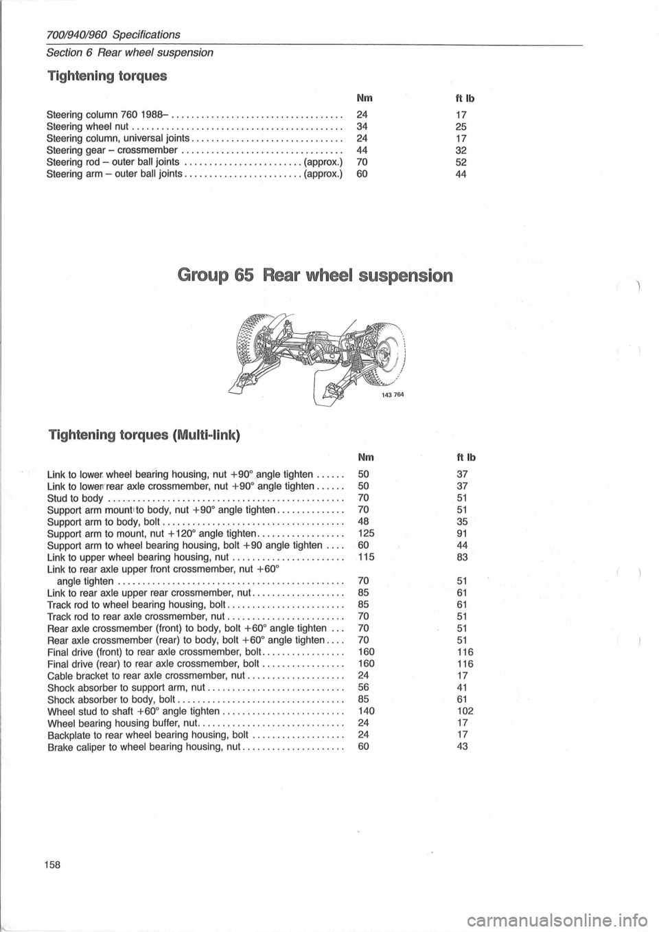
Tightening torques
Nm ftlb
Steering column 760 1988-............................. .. ... .
24 17
Steering wheel nut .
........ ................................. . 34
25
Steering column, universal joints
.............................. .
24 17
Steering gear -
cr
44 32
Steering
rod - outer ' ball joints ........................ (approx .) 70 52
Steering arm -outer
ball joints ........................ (approx.) 60 44
Group 65 Rear wheel suspens ion
Tightening torques (Multi-link)
Nm ft Ib
Link to lower , wheel beBring housing, nut +900~ngle tighten ..... . 50 37
Link to
lowen'rear axle crossmember, nut +900 angle tighten ..... . 50 37
Stud to body ................................................ .. . 70 51
Support arm mount lto body, nut +900 angle tighten ............. . 70 51
Support arm to body, bolt .................................... . 48 35
Support arm to mount, nut + 1200 angle
tighten ................. . 125 91
Support
arm to wheel bearing housing, bolt +90 angle tighten ... . 60 44
Link to upper wheel bearing housing, nut ...... ................ . 115 83
Link
to rear axle upper front crossmember, nut +600
angle tighten ............................................. . 70 51
Link to rear axle upper rear crossmember, nut .................. . 85 61
Track rod to wheel bearing housing, bolt ..................... .. . 85 61
Track rod to rear axle crossmember, nut ....................... . 70 51
Rear axle crossmember (front) to body, bolt +600 angle tighten .. . 70 51
Rear axle crossmember (rear) to body, bolt +600 angle tighten ... . 70 51
Final drive (front) to rear axle crossmember, bolt ................ . 160 116
Final drive (rear) to rear axle crossmember, bolt
................ . 160 116
Cable bracket to rear axle cross member, nut
................... . 24
17
Shock absorber to support arm, nut ........................... . 56 41
Shock absorber to body, bolt ................................. . 85 61
Wheel stud to shaft +600 angle tighten ........................ . 140 102
Wheel
bearing housing buffer, nut. ............................ . 24 17
Backplate to rear wheel bearing housing, bolt
.................. . 24
17
Brake caliper to wheel bearing housing, nut ..
.................. . 60 43
158