1982 VOLVO 960 alternator
[x] Cancel search: alternatorPage 9 of 168
(
Carburettor
Fuel pump
Clutch
Alternator ,
Steering box
SU
Pierburg
Solex Pierburg
Bosch
AC- oelco
Sofabex
Fichtel & Sachs
Verto/Valeo
Bosch
Cam Gear
Zahnrad Fabrik (ZF)
~
'?' .'" ... .
.
---
" .. u.·.. ,
2
3
5
2
3
4
5
2
3
1
2
3
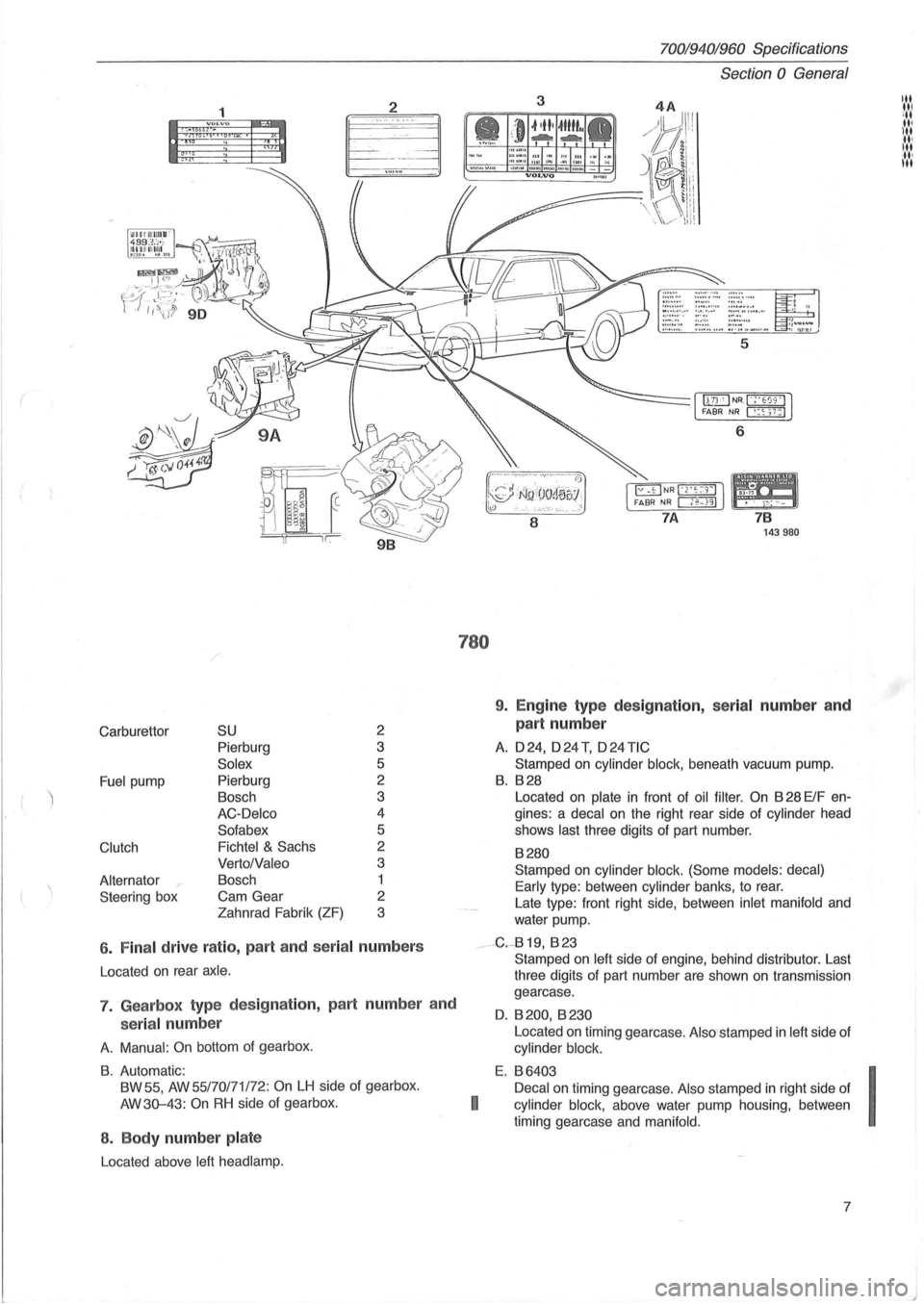
6 . Fina l drive ratio , part and seria l numbers
Located on rear axle .
7. Gearbox type des ig nation, part numbe r and
serial num ber
A. Manual : On bottom of gearbox .
B. Automatic:
BW 55,
AW 55/70171 /72: On LH side of gearbox.
AW3Q-43:
On RH side of gearbox.
8 . Body number pla te
Located above left head lamp.
780
70019401960 Specifications
Section
0 General
3
6
8
7 B 143980
9. Engine type des ig nation, serial number an d
part number
A. 024, o24T, o24TIC
Stamped on cylinder block, beneath vacuum pump.
B. B28
Located on plate in front of oil filter . On B 28 ElF en
gines: a
decal on the right rear side of cylinder head
shows
last three digits of part number.
B280
Stamped on cylinder block. (Some models: decal)
Early
type : between cylinder banks, to rear.
Late type: front right side, between
inlet manifold and
water pump.
__ -G.-819, B 23
I
Stamped on left side of engine, behind distributor. Last
three digits of part number are shown
on transmission
gearcase.
O. B 200, B 230
Located on timing gearcase . Also stamped in left side of
cylinder block.
E. B6403
Decal
on timing gearcase. Also stamped in right side of
cylinder block, above water pump housing , between
timing gearcase and
manifold.
7
I
J
Page 110 of 168
70019401960 Specifications
Section 2 024, 024 T, 024 TIC Engines
Section 2 D 24, D 24 T, D 24 TIC Engines
Group 20 General. . . . . . . . . . . . . . . . . . . . . . . . . . . . .. 108
Group 21 Engine..... ...................... .... 109
Group 22 Lubricating system . . . . . . . . . . . . . . . . . . . . 114
Group 23
Fuel system . . . . . . . . . . . . . . . . . . . . . . . . . . 114
Group 25
Intake and exhaust systems. . . . . . . . . . .. 116
Group 26
Cooling system .. . . . . . . . . . . . . . . . . . . . .. 117
Group 20 Genera l
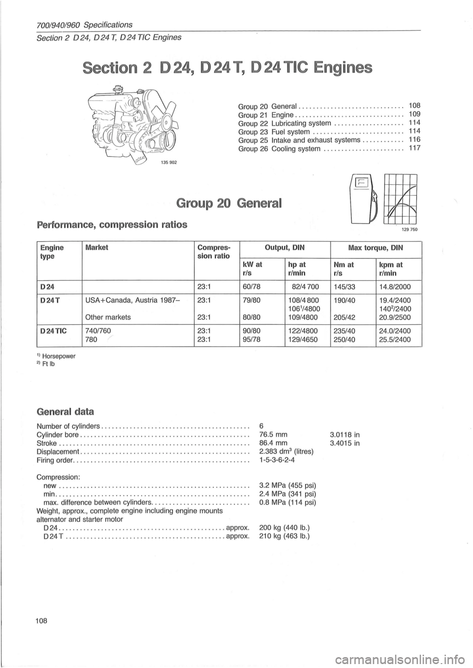
Performance , co mpress io n r atios
Engine Market Compre
s-Output, DIN
type sion
ra tio
kWat hp at
r/s r/min
024 23:1 60/78 8214700
024T USA+Canada, Austria 1987-23:1 79/80 108/4800
106'/4800
Other
markets 23:1 80/80 109/4800
024TIC 740/760 23:1 90/80 12214800
780
23:1 95/78 129/4650
1) Horsepower 2) Ft Ib
Ge ne ra l da ta
Number of cylinders .. ............... ........................ .
Cylinder bore .................... ...................... ..... .
Stroke ..
............................ ............. ... ....... .
Displacement ........ ....................................... .
Firing order ..
............................................... .
Compression: new
..................................................... .
min
....................... ............................... .
max. difference between
cylinders ........................... .
Weight, approx.,
complete engine including engine mounts
alternator and starter motor
D 24 ....
.............. ... ............ ... ........... approx .
D 24 T
............................................. approx.
108
6
76.5 mm
86.4 mm
2.383 dm
3 (Iitres)
1-5-3-6-2 -4
3.2
MPa (455 psi)
2.4
MPa (341 psi)
0.8 MPa (114 psi)
200 kg (440 lb.)
210
kg (463 lb .)
,/1-'"
It
t1 '
'29750
Max torque, DIN
Nm at
r/s
145/33
190/40
205/42
235/40
250/40
3.0118
in
3.4015 in
kpm at
r/min
14.8/2000
19.4/2400
140
2/2400
20.9/2500
24 .0/2400
25 .5/2400
Page 119 of 168
(
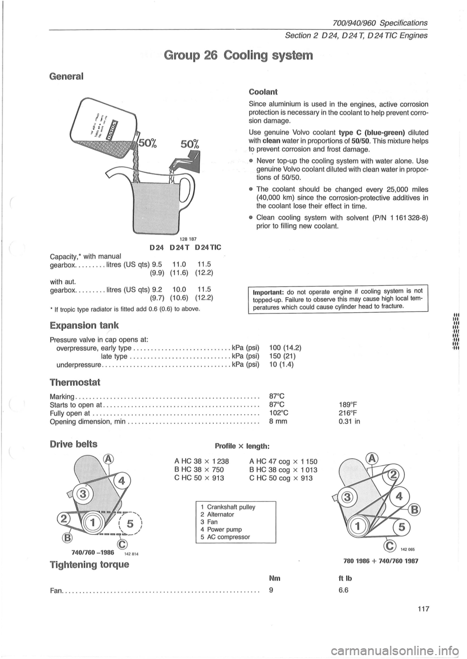
General
024
Capacity: with manual
gearbox ......... litres (US qts) 9.5
(9.9)
with
aut.
gearbox ......... litres (US qts) 9.2
(9.7)
70019401960 Specifications
Section 2 024, 024 T, 024 TIC Engines
Group 26 Cooling system
128187
024T 024TIC
11.0 11.5
(11.6) (12
.
2)
10.0 11.5
(10.6) (12.2)
Coolant
Since aluminium is used in the engines, active corrosion
protection is necessary in the
coolant to help prevent corro
sion damage.
Use genuine Volvo coolant type C (blue-green) diluted
with clean water in proportions of 50/50. This mixture helps
to prevent corrosion and frost damage.
• Never top-up the cooling system with water alone . Use
genuine
Volvo coolant diluted with clean water in propor
tions of 50/50.
•
The coolant should be changed every 25,000 miles
(40,000
km) since the corrosion-protective additives in
the coolant lose their effect in time.
• Clean cooling system with solvent (P/N 1 161 328-8)
prior to
filling new coolant.
• If tropic type radiator is filled add 0.6 (0.6) to above.
Important: do not operate engine if cooling system is not topped-up. Failure to observe this may cause high local temperatures which could cause cylinder head to fracture .
Expansion tank /
Pressure valve in cap opens at:
overpressure, early type ............................ kPa (psi)
late type ............................. kPa (psi)
underpressure
............... ...................... kPa (psi)
Thermostat
Marking ..................................................... .
Starts to open
at ............................................ .
Fully open
at ............................................... .
Opening dimension, min ..................................... .
Drive belts Profile x length:
100 (14.2)
150 (21)
10(1.4)
87°C
87 °C
102°C
8 mm
A HC 38 x 1238
B HC 38 x 750
C HC
50 x 913
A HC 47 cog x 1 150
B HC 38 cog x 1 013
C
HC 50 cog x 913
--, / , I 5 I 1 I
--~_/
7401760 -1986 142814
Tightening torque
1 Crankshaft pulley 2 Alternator 3 Fan 4 Power pump
5 AC compressor
Nm
Fan.......................... ............................... 9
189°F
216 °F
0 .
31 in
780 1986 + 7401760 1987
ftlb
6.6
117
lit til' lit ,", ·111 11,1 ·111 1111 ,11'
--'
Page 120 of 168
70019401960 Specifications
Section 3 Electrical system
Section 3 Electrical system
Group 31 Battery............................... 118
Group 32 Alternator. . . . . . . . . . . . . . . . . . . . . . . . . . . .. 118
Group 33 Starter motor . . . . . . . . . . . . . . . . . . . . . . .
.. 123
Group 35 Lighting......... . . . . . . . . . . . . . . . . . . . .. 127
Group
37 Fuses.... . . . . . . . . . . . . . . . . . . . . . . . . . . .. 128
Group 38 Instrumentation . . . . . . . . . . . . . . . . . . . . . .. 137
Group 31 Battery
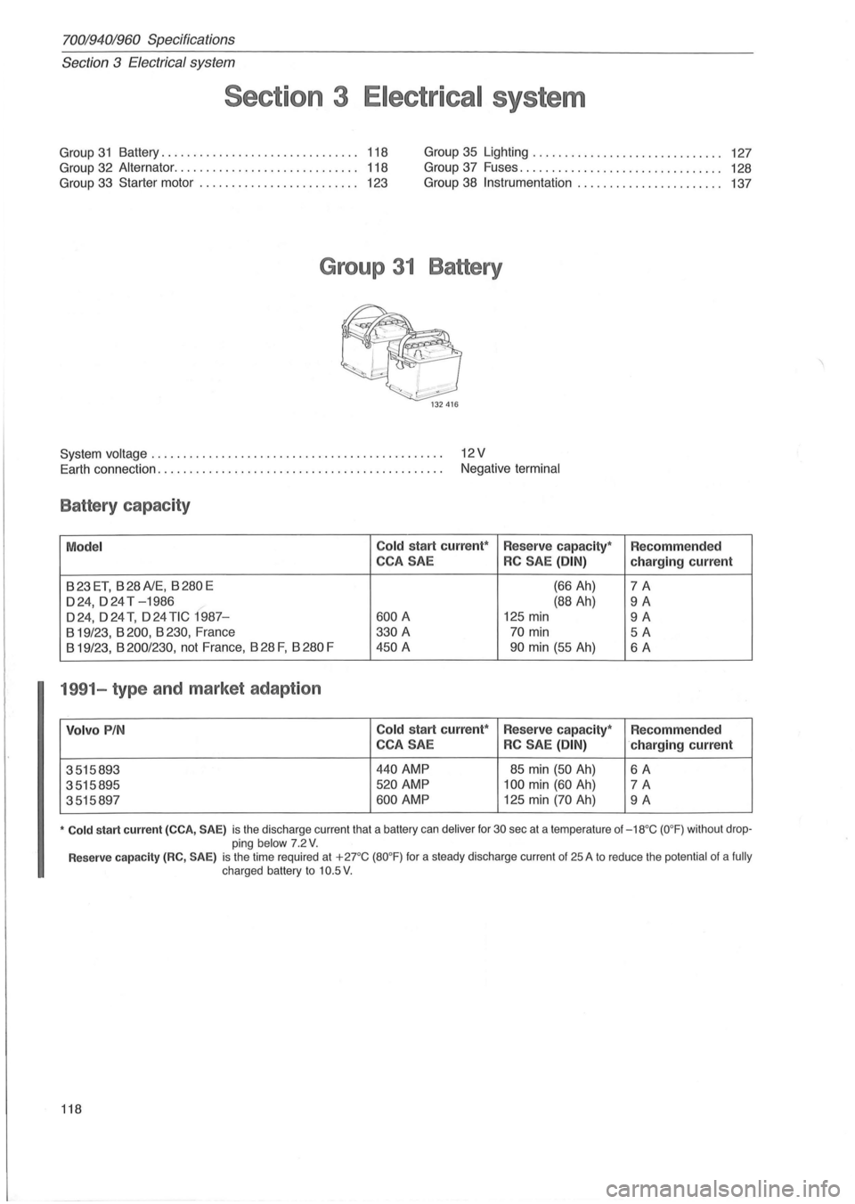
System voltage . . . . . . . . . . . . . . . . . . . . . . . . . . . . . . . . . . . . . . . . . . . . . . 12 V
Earth connection. . . . . . . . . . . . . . . . . . . . . . . . . . . . . . . . . . . . . . . . . . . . . Negative terminal
Battery capacity
Model Co
ld start current*
Reserve capacity* Recommended
CCA SAE
RC SAE (DIN) charging current
B23ET, B28A1E, B280E (66 Ah) 7A
024, 0 24 T -1986 (88 Ah) 9A
024,024 T, 024 TIC 1987-600 A 125 min 9A
B 19/23, B 200, B 230, France 330
A 70 min 5A
B 19/23, B 200/230, not France, B 28 F, B 280 F 450 A 90 min (55 Ah) 6A
1991-type and market adaption
Volvo PIN Cold start current*
Reserve capacity*
Recommended
CCA SAE
RC SAE (DIN) ·charging current
3515893
440 AMP 85 min (50 Ah) 6A
3515895 520 AMP 100 min (60 Ah) 7A
3515897 600 AMP 125 min (70 Ah) 9A
• Cold start current (CCA, SAE) is the discharge current that a battery can deliver for 30 sec at a temperature of -18°C (O°F) without drop
ping below 7 .2 V.
Reserve capacity (RC, SAE) is the time required at + 2rC (80°F) for a steady discharge current of 25 A to reduce the potential of a fully charged battery to 10.5 V .
118
Page 121 of 168
(
70019401960 Specifications
Section
3 Electrical system
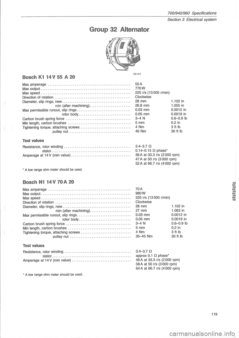
Group 32 Alternator
Bosch K1 14 V 55 A 20
Max amperage ............................................. .
Max output ................................................. .
Max speed ................................................. .
Direction of rotation .
........................................ .
Diameter,
slip rings, new ..................................... .
min (after machining) ...................... .
Max permissible runout, slip rings ............................. .
rotor body
............................ .
Carbon brush spring force
............... .................... .
Min length, carbon brushes .................................. .
Tightening torque, attaching screws
........................... .
pulley nut ................................. .
Test values
Resistance, rotor winding .................................... .
stator
..... ...................................... .
Amperage
at 14 V (min value) ................................ .
, A low range ohm meIer should be used.
Bosch N1 14 V 70 A 20
Max amperage ............................................. .
Max output
................................................. .
Max speed
...................... .. ......................... .
Direction of rotation
......................................... .
Diameter,
slip rings, new ..................................... .
min (after machining)
...................... .
Max permissible runout,
slip rings ............................. .
rotor body
............................ .
Carbon brush spring force
................................... .
Min length, carbon brushes .................................. .
Tightening torque, attaching screws .
.......................... .
pulley nut ................................. .
Test values
Resistance, rotor winding .................................... .
stator
......................................... .. .
Amperage
at 14 V (min value) ................................ .
, A low range ohm meter should be used.
132417
55A
770W
225 rls (13500 r/min)
Clockwise
28 mm
26.8
mm
0.03 mm
0.05 mm
3-4N
5 mm
4 Nm
40 Nm
3.4-3.70
0.14-0.15 0 phase'
1.102 in
1.055 in
0.0012 in
0.0019 in
0.6-0.9Ib
0.2 in
3 ft Ib
30 ft Ib
36 A at 33.3 rls (2000 rpm)
47 A at 50 rls (3000 rpm)
52A at 66.7 rls (4000 rpm)
70A
980W
225 rls (13500 r/min)
Clockwise
28 mm
27 mm
0.03 mm
0.05 mm
3-4N
5 mm
4 Nm
35-45 Nm
3.4-3.70
approx 0.1 0 phase'
1.102 in
1.063 in
0.0012 in
0.0019 in
0.6-0.9Ib
0.2 in
3 ft Ib
30 ft Ib
46 A at 33.3 rls (2000 rpm)
58 A at 50 rls (3000 rpm)
64A at 66.7 rls (4000 rpm)
119
HI Itli til III ·111 III ·tli III ,til
Page 124 of 168
70019401960 Specifications
Section
3 E lectrical system
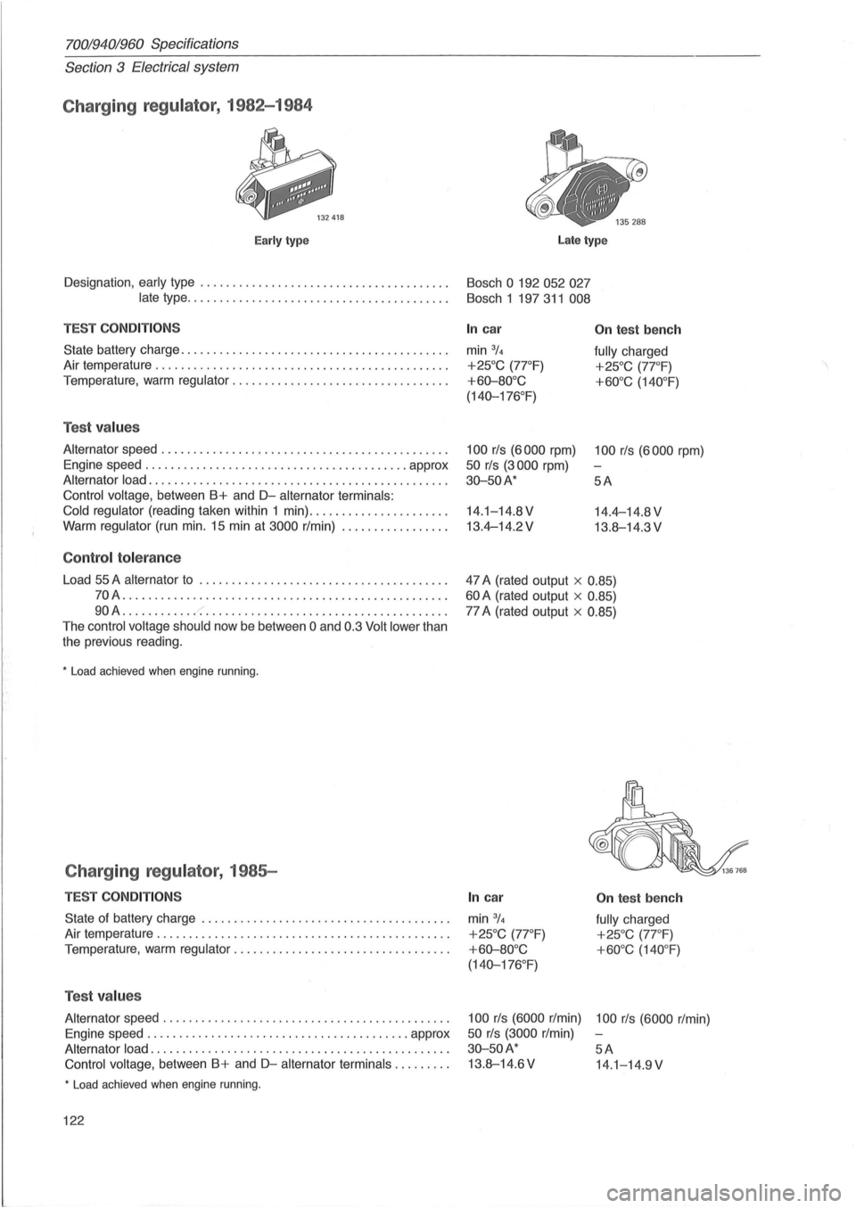
Charging regulator , 1982-1984
Early type Late type
Designation , early type . . . . . . . . . . . . . . . . . . . . . . . . . . . . . . . . . . . . . . . Bosch 0 192 052 027
late
type . . . . . . . . . . . . . . . . . . . . . . . . . . . . . . . . . . . . . . . . . Bosch 1 197 311 008
TEST COND IT IO NS
State battery charge ........................... ............ .. .
Air temperature
.......................... ................... .
Temperature ,
warm regulator ............................. .... .
Tes t values
Alternator speed ...... ...................................... .
Engine speed ..
..... .................................. approx
Alternator load ............ .............................. .... .
Control voltage, between B+ and D-alternator terminals:
Cold regulator
(reading taken within 1 min) .. ................... .
Warm regulator (run min. 15 min at 3000 r/min) ................ .
Co ntrol to le ra n ce
Load 55 A alternator to ........ ........... ... ................ .
70A ................................ .................. .
90A ........ .................................. ........ .
The
control voltage should now be between 0 and 0.3 Volt lower than
the previous reading .
• Load achieved when engine running .
Charging regulator , 1985-
TES T CO NDITION S
State of battery charge ........................ ............ .. .
Air temperature
............................................. .
Temperature, warm
regulator ............... .................. .
Tes t values
Alternator speed ............... ............................. .
Engine speed
............................. ............ approx
Alternator load .................. ............................ .
Control voltage, between B+ and D-alternator terminals ........ .
• Load achieved when engine running .
122
In car
min 3/4
+25°C (7rF)
+60-80°C
(140-176 °
F)
100 rls (6000 rpm)
50 rls (3000 rpm)
30-50A*
14.1-14.8V
13.4-14.2V
On tes t b ench
fully charged
+25°C (7rF)
+60°C (140 °F)
100 rls (6000 rpm)
5A
14.4-14.8 V
13.8-14.3 V
47 A (rated output x
0.85)
60 A (rated output x 0.85)
77 A (rated output x 0.85)
In c ar
min 3/4
+25°C (77 °F)
+ 60-80°C
(140-176 °
F)
On tes t be nch
fully charged
+25°C (7rF)
+60°C (140 °F)
100 rls (6000 r/min) 100 rls (6000 r/min)
50 rls (3000 r/min)
30-50A* 5A
13.8-14.6V 14.1-14 .9V
Page 125 of 168
(
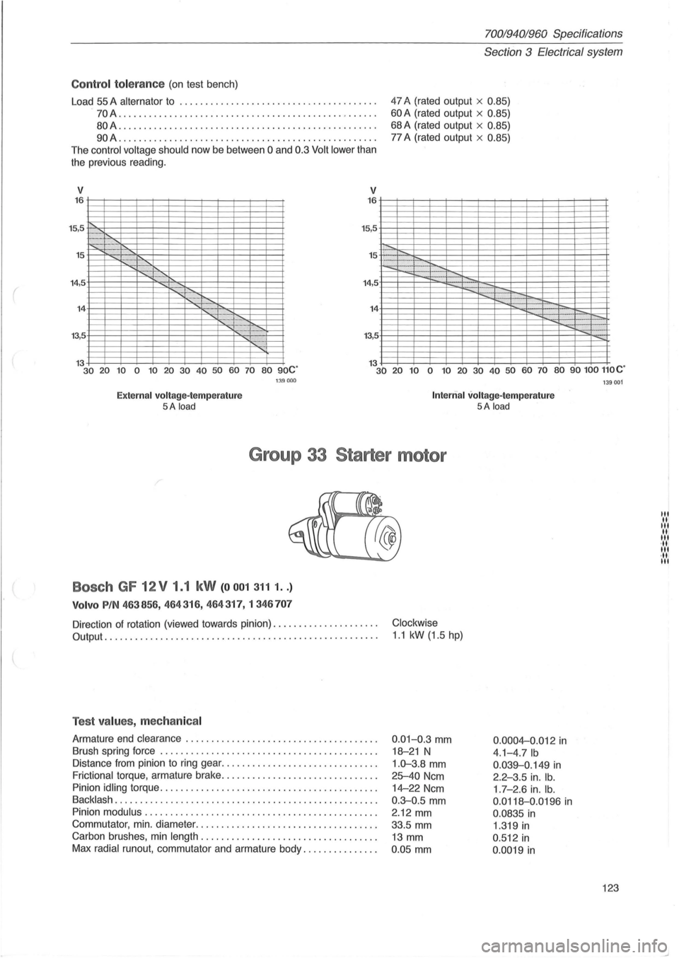
Control to le ra nce (on test bench)
Load
55 A alternator to ............... ............. ....... ... .
.
70A ...................... ........................... . .
80A .................. ...................... .......... .
90A ......... ......................................... .
The
control voltage should now be between 0 and 0.3 Volt lower than
the previous reading.
V 16
15,5 .
15
'"
v
15,5
15 .
14,5 14
13,5
70019401960 Specifications
Section 3 E lectrical system
47 A (rated output x 0.85)
60 A (rated output x 0.85)
68 A (rated output x 0.85)
77 A (rated output x 0.85)
13 30 20 10 0 10 20 30 40 50 60 70 80 90C' 13 30 20 10 0 10 20 30 40 50 60 70 80 90100 110C'
Exte rn al volt age- te m perature 5A load
1:l9000
Int erri al volt age- te mp erature 5A load
G ro up 33 S ta rt er m otor
Bosch GF 12V 1.1 kW (00013111 .. )
V olvo PIN 463856 , 464 316, 464317,1346 707
Direction of rotation (viewed towards pinion) ............... .... . .
Output . . ......................................... , ......... .
Test values , mechan ical
Armature end clearance ....... ................... .......... . .
Brush spring force
.......................................... .
Distance from pinion to ring gear ... .
.......................... .
Frictional torque, armature brake ............................ .. .
Pinion
idling torque ........... .. ...................... ..... .. .
Backlash ..................... .............................. .
Pinion
modulus . .. .............................. ............ .
Commutator , min . diameter
................................... .
Carbon brushes, min
length .. ............................ .... .
Max
radial runout, commutator and armature body ... ........... .
Clockwise
1 .1 kW (1.5 hp)
0.01-0.3 mm
18-21 N
1.0-3.8 mm
25-40 Ncm
14-22 Ncm
0 .
3-0.5 mm
2.12 mm
33.5 mm
13 mm
0 .
05 mm 0.000
4-0
.012 in
4.1-4.7Ib
0 .039-0.149 in
2.2-3.5 in. lb.
1 .7 - 2.6 in. lb.
0.0118-0.0196 in
0.0835 in
1 .319 in
0 .512 in
0 .0019 in
1 39001
123
III III III III III ,11, III ·111 III