1982 VOLVO 960 seats
[x] Cancel search: seatsPage 20 of 168
70019401960 Specifications
Section 2 B 19, B 23 Engines
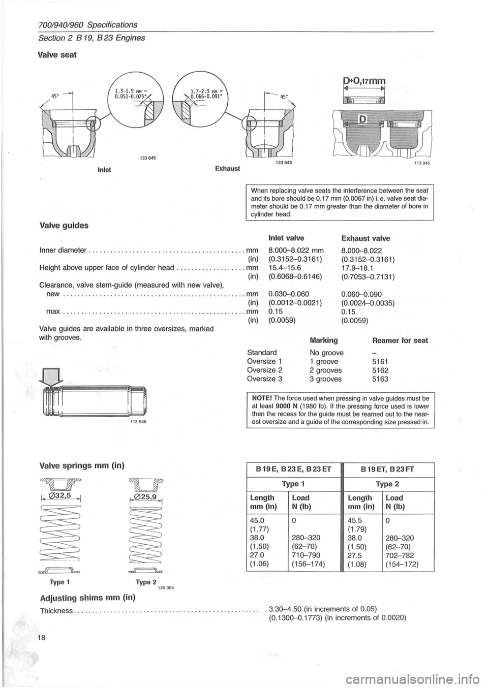
Valve seat
Inlet
Valve guides
Exhaust
D+O,17mm
~\ i~
133646 113945
When replacing valve seats the interference between the seat
and its bore should be 0.17 mm (0.0067 in) i. e . valve seat diameter should be 0.17 mm greater than the diameter of bore in cylinder head.
Inner diameter ........... . ..... ...... ....... ............. mm
Inlet valve
8.000-8.022 mm
(0.3152-0.3161 )
15.4-15.6
(0.6068-0.6146)
Exhaust valve
8.000-8. 022
(0.3152-0.3161 )
17 .
9-18.1
(0.7053-0.7131 )
(in)
Height above upper face of cylinder head ................... mm
(in)
Clearance , valve stem-guide (measured with new valve) ,
new .......... . ...................................... . mm
(in)
max .
................. ................ . ~ .. ,,~ ....... "" ....... mm
(in)
Valve guides are available in three oversizes, marked
with grooves .
0.030-0.060
(0.0012-0.0021
)
0 .15
(0.0059)
Marking
0.060-0.090
(0.0024-0.0035)
0.15
(0.0059)
Reamer for seat
Standard
No groove
V alv e springs mm (in)
~
I. 032,5 . 1
rn~
Typ e 1
113946
wu , .. 025,9 1 I •
..g======'lb
Type 2 135065
Adjusting shim s mm (in)
Oversize 1
1 groove 5161
Oversize 2 2 grooves 5162
Oversize 3 3 grooves 5163
NOTE! The force used when pressing in valve guides must be at least 9000 N (1980 Ib). If the pressing force used is lower
then the recess for the guide must be reamed out to the nearest oversize and a guide of the corresponding size pressed in.
B 19 E, B 23 E, B 23 ET
B 19 ET, B 23 FT
Type 1 Type 2
Length Load
Le
ngth Load
mm (in)
N (Ib) mm (in)
N (Ib)
45.0 0 45.5 0
(1.77)
(1.79)
38.0
280-320 38.0 280-320 (1.50) (62-70)
(1.50) (62-70)
27 .0
710-790 27 .5 702-782
(1.06)
(156-174)
(1.08) (154-172)
Thickness.
. . . . . . . . . . . . . . . . . . . . . . . . . . . . . . . . . . . . . . . . . . . . . . . . . . 3 .30-4.50 (in increments of 0.05) (0. 1300-0.1773) (in increments of 0.0020)
18
Page 40 of 168
70019401960 Specifications
Section 2 B 200, B 230 Engines
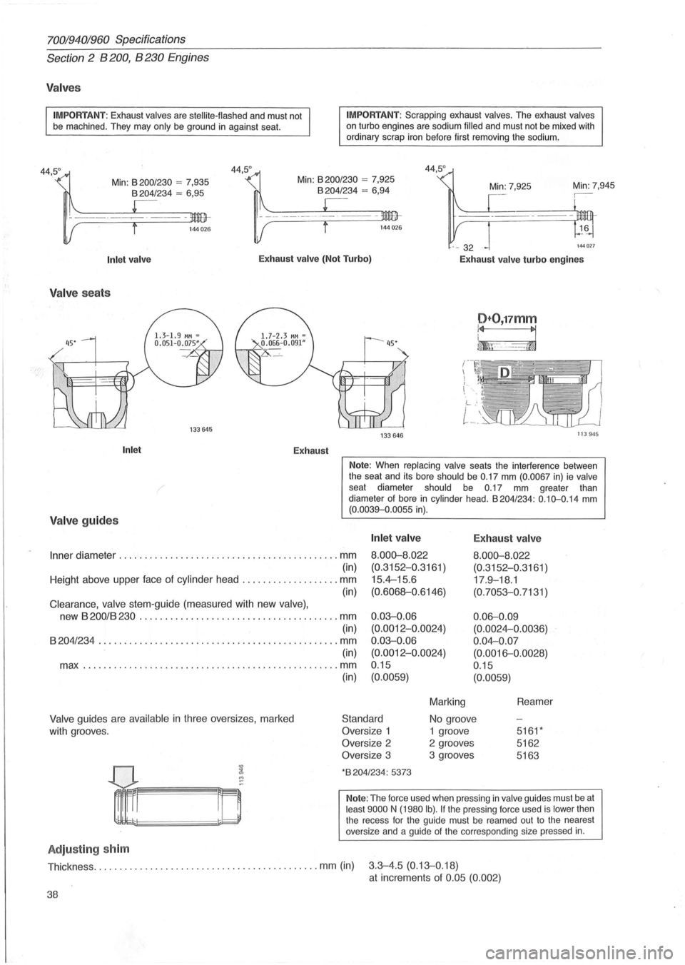
Valves
IMPORTANT: Exhaust valves are stellite-flashed and must not
be machined . They may only be ground in against seat.
Min:
8200/ 230 = 7,935 8204/234 = 6 ,95
IMPORTANT : Scrapping exhaust valves. The exhaust valves on turbo engines are sodium filled and must not be mixed with
ordinary scrap iron before first removing the sodium.
Min: 7,945
144 027
Inlet valve Exhaust valve (Not Turbo)
Exhaust valve turbo engines
Valv e sea ts
Inlet Exhaust
Valve guides
D+O,17mm
~F-~
133 646 113945
Note: When replacing valve seats the interference between
the seat and its bore should be 0.17 mm (0.0067 in) ie valve seat diameter should be 0.17 mm greater than
diameter of bore in cylinder head . 8204/234: 0.10-0.14 mm (0.0039-0 .0055 in).
Inner diameter ........................................... mm
Inlet valve
8.000-8.022
(0.3152-0.3161 )
15.4--15.6
(0.6068-0.6146)
E xhaust valve
8.000-8.022
(0.3152-0 .3161 )
17 .9-18.1
(0.7053-0. 7131 )
(in)
Height above upper face of cylinder head
................... mm
(in)
Clearance, valve stem-guide (measured with new valve),
new 8200/8230 ....................................... mm 0.03-0.06
(0.0012-0.0024)
0.03-0.06
(0.0012-0.0024)
0.15 0
.
06-0.09
(0.0024--0.0036)
0 .04--0 .07
(0.0016-0 .0028)
0.15
(in)
8204/234 ....... ........................................ mm
(in)
max
.............. .................................... mm
Valve guides are available in three oversizes , marked
with grooves.
Adju sting sh im
(in) (0.0059)
Standard
Oversize 1
Oversize 2
Oversize 3
*8204/234: 5373
(0.0059)
Marking
No groove
1 groove
2 grooves
3 grooves Reamer
5161 *
5162
5163
Note:
The force used when pressing in valve guides must be at least 9000 N (1980 Ib). If the pressing force used is lower then
the recess for the guide must be reamed out to the nearest
oversize and a guide
of the corresponding size pressed in.
Thickness ............................................ mm (in) 3.3-4.5 (0.13-0. 18)
at increments of 0.05 (0.002)
38
Page 73 of 168
(
70019401960 Specifications
Section
2 B 28 Engine
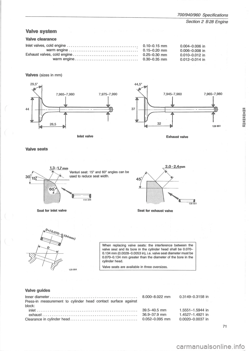
V alve s yste m
Valve clearance
Inlet valves, cold engine ................................. .... .
warm engine ...
................................. :
Exhaust valves, cold engine ..... ................ ............. .
warm engine
................................. .
V alves (sizes in mm)
0.10-0.15 mm
0.15-0.20 mm
0 .25-0.30 mm
0.30-0.35 mm
0 .004-0.006 in
0.006-0.008 in
0.010-0.012 in
0.012-0.014 in
7,975-7,990 7,965-7,980
44
Valve seats
Seat for inlet
valve Inlet
valve
Venturi seat: 15° and 60° angles can be
used to reduce seat width.
Exhaust valve
,
I:i~~' 13 0021
Seat for exhaust valve
When replacing valve seats: the interference between the valve seat and its bore in' the cylinder head shall be 0 .070-0.134 mm (0.0028-0.0053 in), i.e. valve seat diameter must be 0.070-0.134 mm greater than the diameter of the bore in the cylinder head.
Valve seats are available in three oversizes .
Valve guide s
Inner diameter ................. ............................. .
Press -in measurement to cylinder head contact surface against
block:
inlet
............................................... ...... .
exhaust ..
............... ................................. .
Clearance in cylinder head ............. ...................... .
8 .000-8.022 mm
39.5-40.5 mm
36.9-37.9 mm
0.052-0.095 mm
0 .3149-0.3158 in
1.5551-1 .5944 in
1.4527-1.4921 in
0.0020-0. 0037 in
129851
71
Page 90 of 168
70019401960 Specifications
Section 2 B 280 Engine
Valve system
Valve clearance
Inlet valves, cold engine ..................................... .
warm engine
................................... . .
Exhaust valves, cold engine
.................................. .
warm engine
................................. .
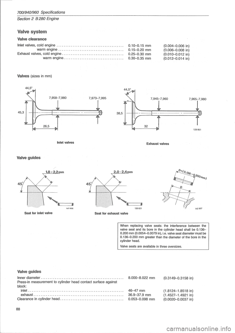
Valves (sizes in mm)
44,5°
0.10-0.15 mm
0.15-0.20 mm
0.25-0.30 mm
0.30-0.35 mm
(0.004-0.006 in)
(0.006-0.008 in)
(0.010-0.012 in)
(0.012-0.014 in)
7,973-7,995
7,965-7,980
45,3
129851
Inlet valves Exhaust valves
Valve guides
18-22mm 20-24mm
'·Il'I====JI, '·':1 ~:J' 141 RClfj 130021
Seat for Inlet valve
Seat for exhaust valve
When replacing valve seats: the interference between the valve seat and its bore in the cylinder head shall be 0.136-0.200 mm (0.0054-0.0079 in), i.e. valve seat diameter must be 0.136-0.200 mm greater than the diameter of the bore in the cylinder head .
Valve seats are available in three oversizes .
Valve guides
Inner diameter .............................................. .
Press-in measurement to cylinder head contact surface against
block: inlet .
.................................................... .
exhaust
........................... ....................... .
Clearance
in cylinder head ................................... .
88
8.000-8.022 mm
46-47 mm
36.9-37.9 mm
0.053-0.098 mm
(0.3149-0.3158 in)
(1.8124-1.8518 in)
(1.4527-1.4921 in)
(0.0020-0 .0037 in)
Page 101 of 168

(
Cylinder block
Bore
Standard (marked C)
........................... ....... mm (in)
(marked
D) ........... ....................... mm (in)
(marked
E) .................................. mm (in)
(marked
G) ................... . .............. mm (in)
Rebore if wear exceeds 0.1 mm and oil consumption is abnormally high.
Pistons
Piston diameter
Diameter to be measured at right
angles to gudgeon pin and
16 mm from bottom of piston.
Standard (marked C)
.................................. mm (in)
(marked
D): ................................ . mm (in)
(marked
E) .. , ........................ ....... mm (in)
(marked
G) ............ ...................... mm (in)
Piston weight
.......................................... g (oz)
Max weight difference between pistons in same engine
......... g
Piston rings
Axial clearance in piston groove ............................ mm
in
Ring gap (measured in cylinder, bore 83.00 mm) ............. mm ? in
Gudgeon (P iston ) pins
Fit in connecting rod ......................................... .
in piston
................................................ .
Valve system
Hydraulic
Valves
Length inlet ...... .................................... mm (in)
exhaust
.............. ......................... mm (in)
Matching surface
angle .................................. .... 0
Edge height, new valve ................................ mm (in)
min after machining .
...................... mm (in)
Max machining of
valve stem ................ ........... mm (in)
Valve Seats
Diameter standard .................................... mm (in)
oversize
.... ................................ mm (in)
Matching surface
angle .......................... ............ 0
Reduction angle, upper ...................................... 0
lower ................. ....... .............. 0
Width ...................................... ... ...... mm (in)
70019401960 Specifications
Section 2 B 6304 Engine
83.00-83.01
83.01-83 .02
83.02-83.03
83.04-83.05
82.98--82.99
82.99--83.00
83.00-83.01
83.02 -83.03
350
± 5
10
(3.2677-3 .2681 )
(3.2681-3.2685)
(3.2685-3 .2689)
(3.2693-3.2697)
(3.2669--3.26 7
3)
(3.2673-3.2677)
(3.2677-3.
2681 )
(3.2685-3.2689)
(12.5 ±
0.2)
(0.4)
Upper
camp. rings
0.05-0.085
0.0020-0.0033
0.2-0.4
0.008--0.016
Lower
camp. rings
0.03-0.065
0.0012-0.0026
0.2-0.4
0.008--0.016
Oil scraper
ring s
0.02-0.055
0.0008 -0.0022
0.25-0.5
0.009--0 .020
Light thumb pressure (close running fit)
Thumb pressure (push fit)
104.05±0.18
103.30±0.18
45.5
1.5
1.2
0 .4 (4
.
096±0.007)
(4.067±0. 007)
(0.059)
(0.047)
(0.016)
inl et exhaust
32.61 (1.284) 28.61 (1.126)
33.11
(1.304) 29 .11 (1.146)
45.25 45.25
20.25 15.25
60.25 60.25
1.4-1.8 (0.055-0.071) 1.8--2.2 (0.071-0.087)
99
Itl
It
Itl
.... 1 '11 Itl ... Itl
Page 113 of 168
(
70019401960 Specifications
Section 2
024, 024 T, 024 TIC Engines
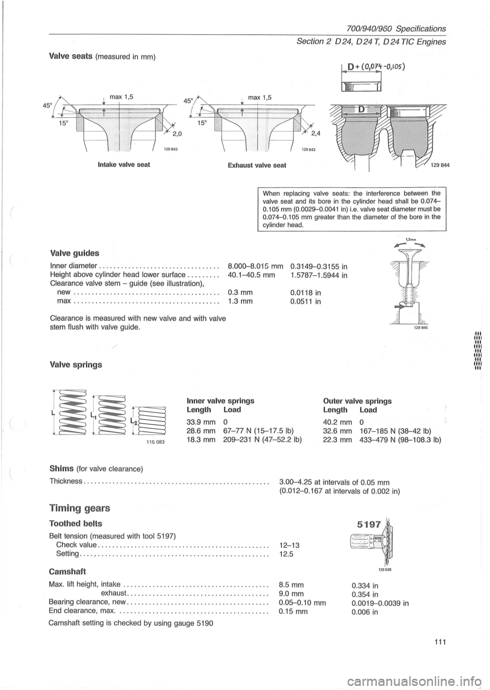
Valve seats (measured in mm)
I!+ (O'O~rIOS)
I max 1,5
129843
Intak e valve sea t
Exhaust valv e seat
When
replacing valve seats: the interference between the valve seat and its bore in the cylinder head shall be 0.074-
0.105 mm (0.0029-0 .0041 in) i.e. valve seat diameter must be 0.074-0.105 mm greater than the diameter of the bore in the cylinder head .
Valve guides
Inner diameter ............... ................. .
Height above cylinder head
lower sur1ace ........ .
8.000-8.015 mm 0 .3149-0.3155 in
40.1-40.5 mm 1 .5787-1.5944 in Clearance valve stem -guide (see illustration),
new........................................ 0.3 mm
max.. ...................................... 1.3 mm
Clearance is measured with new valve and with valve
stem flush with valve guide.
/
Valve springs
Inner va lv e spring s
Length Load
33.9 mm 0 0.0118
in
0.0511 in
Outer
valve springs
Length Load
40.2 mm 0
1,3mm '-.~
115083
28.6 mm 67-77 N (15-17 .5 Ib)
18.3 mm 209-231 N (47-52.2 Ib)
32.6 mm 167-185 N (38-42 Ib)
22.3 mm 433-479N (98-108.3 Ib)
S him s (for valve clearance)
Thickness. . . . . . . . . . . . . . . . . . . . . . . . . . . . . . . . . . . . . . . . . . . . . . . . . . .
3.00-4.25 at intervals of 0.05 mm
(0.012-0 .167 at intervals of 0 .002 in)
Timing gears
Toothed belts
Belt tension (measured with tool 5197)
Check
value. . . . . . . . . . . . . . . . . . . . . . . . . . . . . . . . . . . . . . . . . . . . . . . 12-13
Setting
... . , . . . . . . . . . . . . . . . . . . . . . . . . . . . . . . . . . . . . . . . . . . . . . . . 12.5
Camshaft
Max. lift height , intake ....................................... .
exhaust
...................................... .
Bearing clearance, new .
..................................... .
End clearance , max. . ....................................... .
Camshaft setting
is checked by using gauge 5190
8.5 mm
9.0 mm
0.05-0.10 mm
0 .15 mm
133536
0.334 in
0.354 in
0.0019-0.0039 in
0.006 in
111
·111 1111 ·111 1111 ·111 1111 11 .... 1 III
Page 130 of 168
7001940;'960 Specifications
Section 3 Electrical System
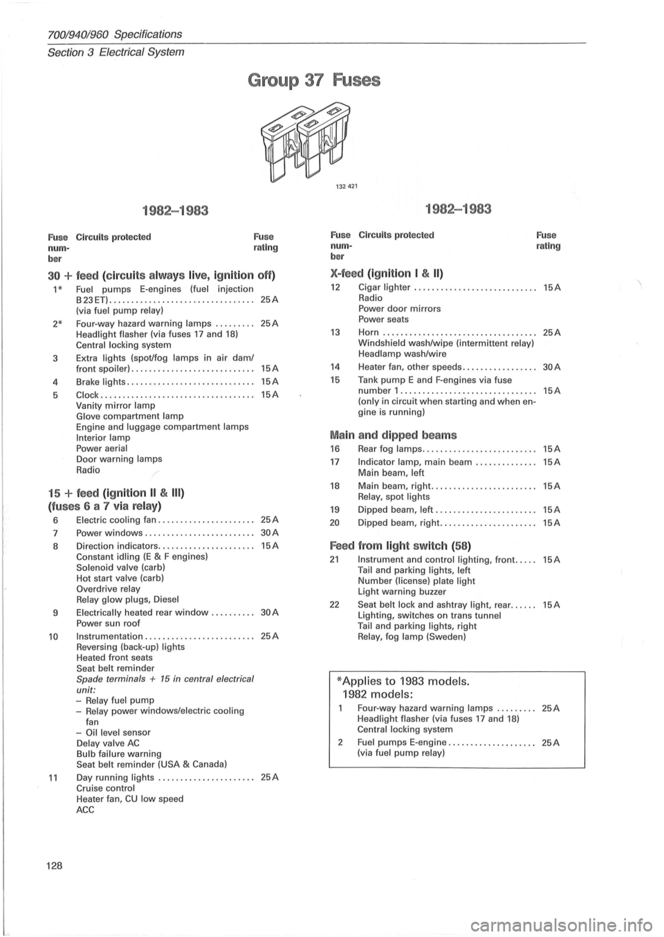
Group 37 Fuses
1982-1983
Fu se Circuits protected
num -
ber Fuse
rating
30 + feed (c ir cu its alw ays live, ig nition off)
1 * Fuel pumps E-engines (fuel injection
B23ET) ........................... ...... 25A (via fuel pump relay)
2* Four-way hazard warning lamps ........ . 25A Headlight flasher (via fuses 17 and 18) Central locking system
3 Extra
lights (spot/fog lamps in air dam/
4
5
front spoiler) ............................ 15A
Brake lights ............. ................ 15A
Clock .......................... ......... 15A Vanity mirror lamp
Glove compartment lamp Engine and luggage compartment lamps
Interior lamp
Power aerial Door warning lamps
Radio
15 + feed (ignition II & III)
(fu ses 6 a 7 via relay)
6 Electric cooling fan ...................... 25A
7 Power windows .................. ....... 30A
8 Direction indicators ...................... 15A Constant idling (E & F engines) Solenoid valve (carb)
Hot start valve (carb)
Overdrive relay
Relay glow plugs , Diesel
9 Electrically heated rear window. . . . . . . . .. 30 A
Power sun roof
10 Instrumentation ...................... , .. 25A Reversing (back-up) lights Heated front seats
Seat belt reminder Spade terminals + 15 in central electrical
unit:
-Relay fuel pump -Relay power windows/electric cooling
fan
-Oil level sensor Delay valve AC Bulb failure warning
Seat belt reminder (USA & Canada)
11 Day running lights ...................... 25A Cruise control
128
Heater fan, CU low speed
ACC
1982-1983
Fuse Circuits protected
num -
ber
X-feed (ign ition I & II)
Fuse rating
12 Cigar lighter ... ......................... 15A Radio
Power door mirrors
Power seats
13 Horn ................................ ... 25A Windshield wash/wipe (intermittent relay)
Headlamp wash/wire
14 Heater fan, other speeds. . . . . . . . . . . . . . . .. 30 A
15 Tank pump E and F-engines via fuse number 1 .............................. . (only in circuit when starting and when engine is running)
Ma in and dipped beams
16 Rear fog lamps ......... .................
17 Indicator lamp, main beam .............. Main beam, left
18 Main beam, right. ....................... Relay, spot lights
19 Dipped beam, left .......................
20 Dipped beam, right ......................
Feed from light switch (58 )
15A
15A
15A
15A
15A
15A
21 Instrument and control lighting, front ..... 15A Tail and parking lights, left Number (license) plate light Light warning buzzer
22 Seat belt lock and ashtray light, rear ...... 15A Lighting, switches on trans tunnel
Tail and parking lights, right Relay, fog lamp (Sweden)
* Applies to 1983 models.
1982 models:
Four-way hazard warning lamps ......... 25A Headlight flasher (via fuses 17 and 18) Central locking system
2
Fuel pumps E-engine .................... 25A (via fuel pump relay)
Page 131 of 168
(
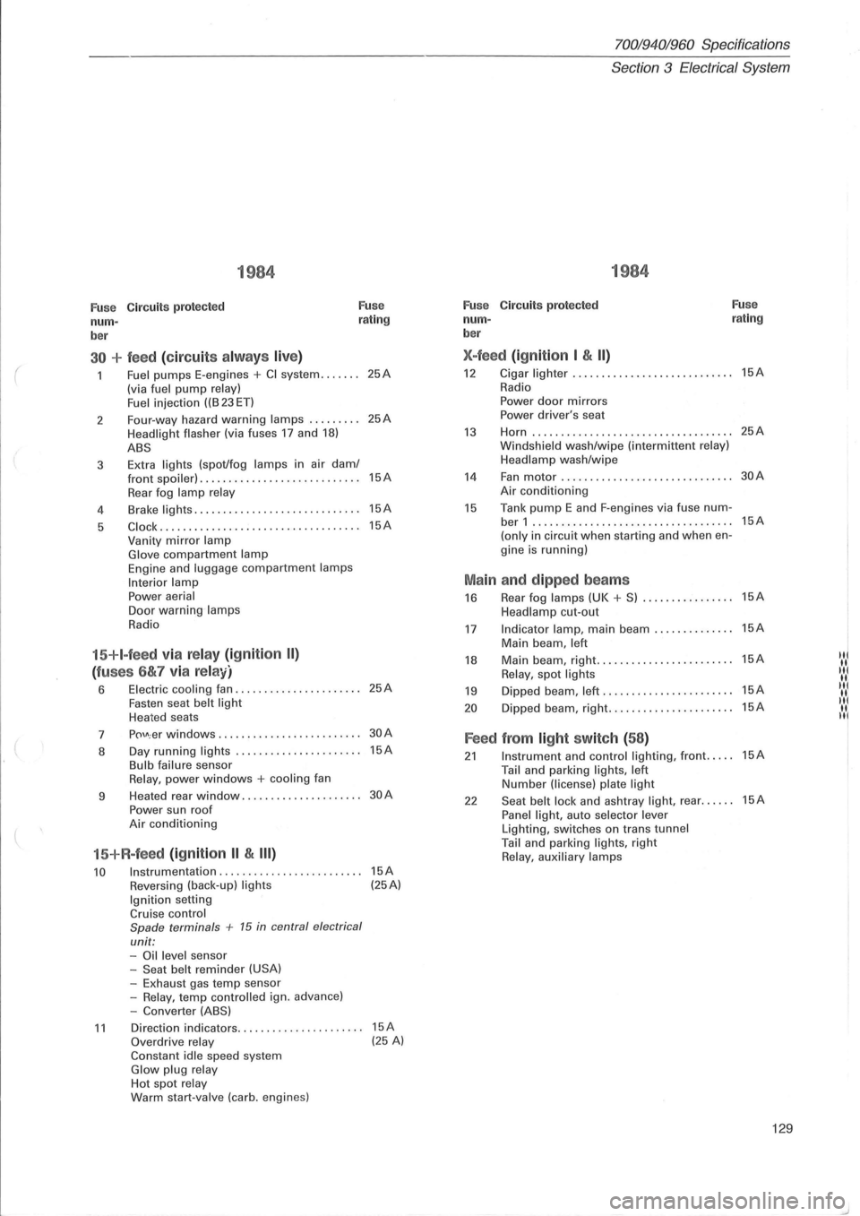
1984
Fuse Circuits protected Fuse
num-rating
ber
30 + feed (circuit s alw ays live)
Fuel pumps E-engines + CI system ....... (via fuel pump relay)
Fuel i njection ((B 23 ET)
2 Four-way
hazard
warning lamps ......... Headlight flasher (via fuses 17 and 18)
ABS
3 Extra lights (spot/fog lamps in
air dam/ front spoiler) . ................ ... .. ......
Rear fog lamp relay
4 Brake lights .....
.. .............•........
5 C lock ....... ............. ............. ..
Vanity mirror lamp Glove compartment lamp Engine and luggage compartment lamps
Interior lamp Power aerial Door warning lamps
Radio
15+I-feed via relay (ignition II)
(fuses 6&7 via relay)
6 Electric cooling fan ................ ...... Fasten seat belt light Heated seats
7
p()\J\; er windows ........... . •.... ........
8 Day
running
lights ..... .......... ....... Bulb failure sensor Relay, power windows + cooling fan
9 Heated
rear
window ................. ....
Power sun roof Air conditioning
15+R-feed (ignition II & III)
10 Instrumentation ........................ .
Reversing (back-up) lights Ignition setting Cruise control
Spade terminals + 15 in central electrical
unit: -Oil level sensor
-Seat belt reminder (USA) -Exhaust gas temp sensor
-Relay, temp contro lled ign. advance)
-Converter (ABS)
25A
25A
15A
15A
15A
25A
30A
15A
30A
15A (25A)
11 Direction indicators.. .. .... .. . .... .. ..... 15A Overdrive relay (25 A) Constant idle speed system Glow plug relay Hot spot relay Warm start-valve (carb. engines)
70019401960 Specifications
Section
3 Electrical System
1984
Fuse C ircuit s protected Fuse
num-rating
ber
X-feed (ignition I & II)
12 Cigar lighter ...... ..............•....... 15A
Radio
Power door mirrors Power driver's seat
13 Horn ...... ........... .. ................ 25A
Windsh ield wash/wipe (interm ittent relay)
Headlamp wash/wipe
14 Fan motor .................. ......... ... 30A
Air conditioning
15 Tank pump E and F-engines via fuse num-ber 1 ...... ...................... ....... 15A
(only in circuit when starting and when en-
gine is running)
Main and dipped beams
16 Rear fog lamps (UK + S) ................ 15A
Headlamp cut-out
17 Indicator lamp, main beam .............. 15A
Main beam , left
18 Main beam, right .......•... ............. 15A IN
Relay, spot lights "I
19 Dipped beam, left ...... ................. 15A IIII( II.
20 D ipped beam, right ...........•.......... 15A "I II. II
Feed from light switch (58)
21 Instrument and control lighting, front ..... 15A
Tail and parking lights, left Number (license) plate light
22 Seat belt lock and ashtray light, rear ...... 15A
Panel light, auto selector lever Lighting, switches on trans tunnel Tail and parking lights, right Relay, auxiliary lamps
129