1982 VOLVO 960 engine
[x] Cancel search: enginePage 115 of 168
(
70019401960 Specifications
Section
2 024, 024 T, 024 TIC Engines
Tig ht enin g to rqu es
Tightening torques apply to oiled bolts and nuts. Oegreased (washed) parts should be oiled prior to assembly .
I' ~ ~ 0 8 CD 0 (IJ
#' ~ G e Q e Q GJ
128149
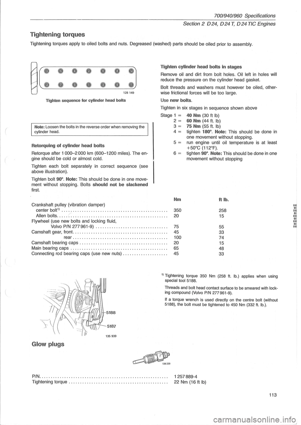
Tighten
sequence for cylinder head bolts
Note: Loosen the bolts in the reverse order when removing the cylinder head.
R etorquing of cylinder head bolts
Retorque after 1 000-2000 km (600-1200 miles). The en
gine
should be cold or almost cold.
Tighten each bolt separately in correct sequence (see
above
illustration).
Tighten bolt 90°. Note: This should be done in one move
ment without stopping.
Bolts should not be slacken ed
first.
Crankshaft
pulley (vibration damper) Ti
g
hten cylinde r h ea d bolts in stages
Remove oil and dirt from bolt holes. Oil left in holes will
reduce the pressure on the cylinder head gasket.
Bolt threads and washers must however be oiled, other-
wise
frictional forces will be too large.
Use new bolts .
Tighten in six stages in sequence shown above
Stage 1 = 40 Nm (30 ft Ib)
2 = 60 Nm (44 ft. Ib)
3 = 75 Nm (55 ft. Ib)
4 = tighten 180°. Note: This should be done in
one movement without stopping .
5
= run engine until oil temperature is at least
+50°C (112°F).
6 = tighten 90°. Note: This should be done in one
movement without stopping
Nm
ft lb.
center bolt1) ............................... ............... . 350 258
Allen bolts ..... :: ......................................... . 20 15
Flywheel (use new bolts and locking fluid,
Volvo PIN
277 961-9) ............................... .
75
55
Camshaft gear, front
......................................... .
45
33
rear
....................................... .. . 100 74
Camshaft bearing caps .................................... .. . 20 15
Main bearing caps .......................................... .
65 48
Connecting rod bearing caps (use new nuts)
................... .
45
33
1) Tightening torque 350 Nm (258 ft. lb.) applies when using special tool 5188.
5187
G lo w plugs
Threads and bolt head contact surface to be smeared with locking compound (Volvo PIN 277961-9).
If a torque wrench is used directly on the centre bolt (without 5188), the bolt must be tightened to 450 Nm (332 ft. lb.) .
PIN.
. . . . . . . . . . . . . . . . . . . . . . . . . . . . . . . . . . . . . . . . . . . . . . . . . . . . . . . . 1 257889-4
Tightening
torque. . . . . . . . . . . . . . . . . . . . . . . . . . . . . . . . . . . . . . . . . . . . 22 Nm (16 ft Ib)
113
'il IN 11 '11 11
·11 III
Page 116 of 168
70019401960 Specifications
Section 2 024, 024 T, 024 TIC Engines
Group 22 Lubricating system
General
Oil capacity and quality, see page 12.
Oil pressure with an oil temperature of +80°C = 176°F and
engine speed of 33.3 rls (2000 r/min) , at least. . . . . . . . . . . . . . . . . . . 200 kPa 28 psi
Oil pressure sensor
Cut-out point, indicator lamp goes out at. ...................... . 15-45 kPa (2.1-6.4 psi)
Lubricating oil pump ,
Relief valve opens at ........................................ . 600-700 kPa (85-99 psi)
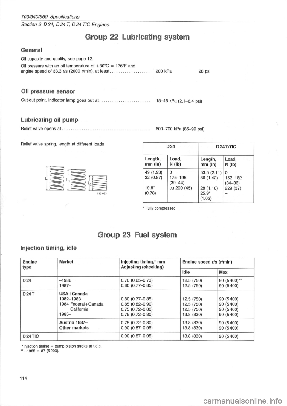
Relief valve spring, length at different loads 024 o 24TfTlC
Length, Load,
Length, Load,
mm (in) N (Ib) mm (in) N (Ib)
49 (1.93) 0 53.5 (2.11) 0 22 (0.87)
175-195
36 (1.42) 152-162
(39-44) (34-36)
19.8 * ca 200 (45)
28(1.10) 229 (37)
115 083 (0.78) 25.9 * -
(1.02)
* Fully compressed
Group 23 Fuel system
Injection timing, idle
Engin e Market
type
024 -1986
1987-
024T USA+Can ada
1982-1983
1984
Federal + Canada
California
1985-
Austr ia 1987 -
Other markets
024TIC
*Injection timing = pump piston stroke at t.d .c . ** - 1985 = 87 (5200).
114
Injecting timing, * mm
Engine speed rls (r/min)
Adjusting (check ing)
Idle Max
0.70 (0.65-0 .73)
12.5 (750) 90 (5400)* *
0.80 (0.77-0.85) 12.5 (750) 90 (5400)
0.80
(0.77-0 .85) 12.5 (750) 90 (5400)
0.85 (0.82-0 .90) 12.5 (750) 90 (5400)
0.75 (0.72- 0 .80) 12.5 (750) 90 (5400)
0.75 (0.72-0 .80) 13.8 (830) 90 (5400)
0.75 (0.72-0.80) 13.8 (830) 90 (5400)
0 .90
(0.87-0 .95) 13.8 (830) 90 (5400)
0.90
(0.87-0.95) 13. 8 (830) 90 (5400)
Page 117 of 168
(
l
70019401960 Specifications
Section
2 024, 024 T, 024 TIC Engines
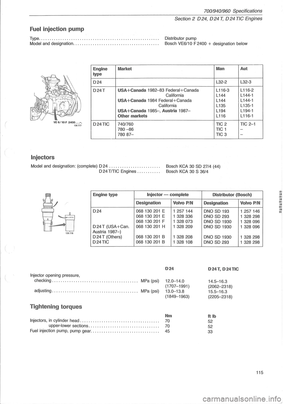
Fuel inject ion pump
Type ....................................................... . Distributor pump
Model and designation ....................................... .
Bosch VE6/10 F 2400 + designation below
VE 6/10 F 2400 ••. -. 136777
Injectors
I
Eng ine
type
024
o24T
o24TIC
Market
U
SA+Canada 1982-83 Federal+Canada
California
U
SA+Canada 1984 Federal+Canada
California
USA+Canada 1985-, Austria 1987-
Other markets
7401760
780 -86
78087-
Man
L32-2
L
116~3
L144
L144
L135
L194
L116
i 1'IC 2 : ' TIC 1
TIC 3
Model
and designation: (complete) 024 . . . . . . . . . . . . . . . . . . . . . . . . Bosch KCA 30 SO 27/4 (44)
024 TITIC Engines . . . . . . . . . . . Bosch KCA 30 S 36/4
Aut
L32-3
L 116-2
L 144 -1
L144-1
L
135-1
L194- 1
L116-1
TIC 2-1
-
-
Eng ine typ e Injector -.complete Distributor (Bosc h)
Designation
024 068130201 E
068130201 E
068130201 F
024 T (USA+Can . 068130201 H
136778 Austria 1987-)
024 T (Others) 068130201 B
o24TIC 068130201 B
Injector opening pressure,
checking. . . . . . . . . . . . . . . . . . . . . . . . . . . . . . . . . . . . . .
.. MPa (psi)
adjusting. . . . . . . . . . . . . . . . . . . . . . . . . . . . . . . . . . . . . . .. MPa (psi)
Tightening torques
Volvo PIN
1 257144
1 328336
1 328073
1 328209
1 328208
1 328 108
024
12.0-14.0
(1707-1991)
13.0-13.8
(1849-1963)
Nm
Injectors, in cylinder head. . . . . . . . . . . . . . . . . . . . . . . . . . . . . . . . . . . . . 70
upper-lower sections. . . . . . . . . . . . . . . . . . . . . . . . . . . . . . . . . 70
Fuel injection pump, pump gear. . . . . . . . . . . . . . . . . . . . . . . . . . . . . . . . 45
Designation
oNO SO 193
oNO SO 293
oNO SO 1930
oNO
SO 1930
oNO
SO 1930
oNO SO 293
024 T, 024 TIC
14.5-16 .3
(2062-2318)
15.5-16.3
(2205-2318)
ftlb
52
52
33
Volvo PIN
1 ,257146
1
328298
1 328096
1 328096
1 328298
1
328298
115
Page 118 of 168
70019401960 Specifications
Section
2 024, 024 T, 024 TIC Engines
Group 25 Intake and exhaust systems
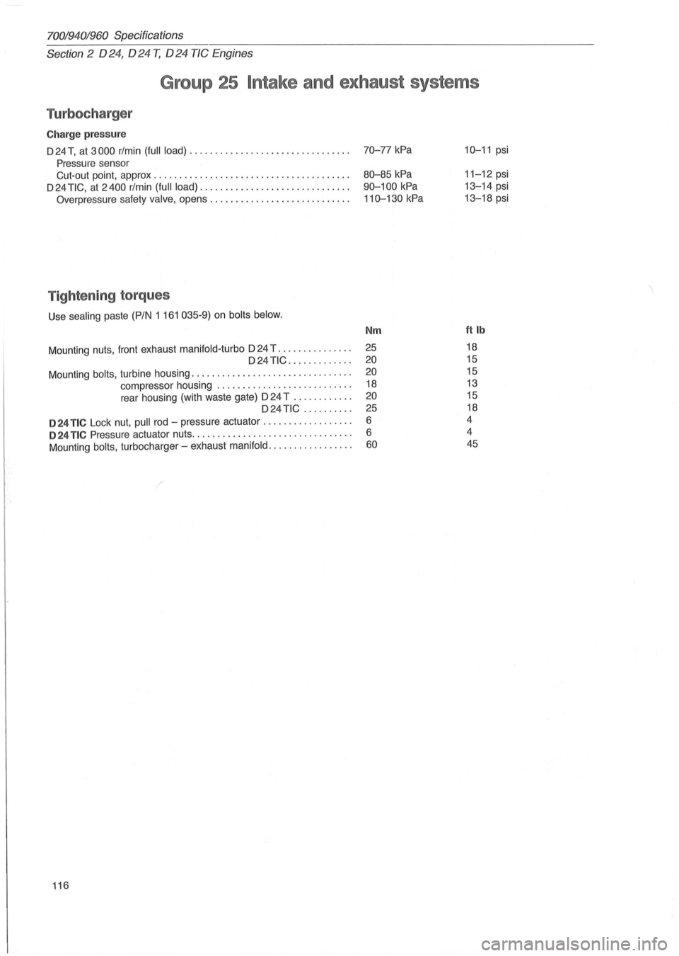
Turbocharger
Charge pressure
D 24 T, at 3000 rlmin (full load) ............................... .
Pressure sensor
Cut-out point, approx
.................................... .. .
D 24
TIC, at 2400 rlmin (full load) ............................. .
Overpressure safety valve, opens ........................... .
Tightening torques
Use sealing paste (PIN 1 161 035-9) on bolts below.
Mount ing nuts, front exhaust manifold-turbo D 24 T .............. . D24TIC ............ .
Mounting
bolts, turbine housing ............................... .
compressor housing
..................... ..... .
rear housing (with waste gate)
024 T ........... .
D24 TiC ......... .
024 TIC Lock nut, pull rod -pressure actuator ................. .
024 TIC Pressure actuator nuts ............................... .
Mounting
bolts, turbocharger -exhaust manifold ................ .
116
70-77 kPa
80-85 kPa
90-100
kPa
110-130 kPa
Nm
25
20
20
18
20
25
6
6
60
10-11 psi
11-12 psi
13-14 psi
13-18 psi
ftlb
18
15
15
13
15
18
4
4 45
Page 119 of 168
(
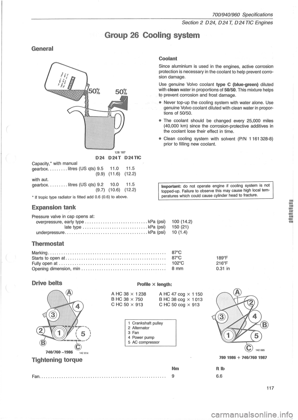
General
024
Capacity: with manual
gearbox ......... litres (US qts) 9.5
(9.9)
with
aut.
gearbox ......... litres (US qts) 9.2
(9.7)
70019401960 Specifications
Section 2 024, 024 T, 024 TIC Engines
Group 26 Cooling system
128187
024T 024TIC
11.0 11.5
(11.6) (12
.
2)
10.0 11.5
(10.6) (12.2)
Coolant
Since aluminium is used in the engines, active corrosion
protection is necessary in the
coolant to help prevent corro
sion damage.
Use genuine Volvo coolant type C (blue-green) diluted
with clean water in proportions of 50/50. This mixture helps
to prevent corrosion and frost damage.
• Never top-up the cooling system with water alone . Use
genuine
Volvo coolant diluted with clean water in propor
tions of 50/50.
•
The coolant should be changed every 25,000 miles
(40,000
km) since the corrosion-protective additives in
the coolant lose their effect in time.
• Clean cooling system with solvent (P/N 1 161 328-8)
prior to
filling new coolant.
• If tropic type radiator is filled add 0.6 (0.6) to above.
Important: do not operate engine if cooling system is not topped-up. Failure to observe this may cause high local temperatures which could cause cylinder head to fracture .
Expansion tank /
Pressure valve in cap opens at:
overpressure, early type ............................ kPa (psi)
late type ............................. kPa (psi)
underpressure
............... ...................... kPa (psi)
Thermostat
Marking ..................................................... .
Starts to open
at ............................................ .
Fully open
at ............................................... .
Opening dimension, min ..................................... .
Drive belts Profile x length:
100 (14.2)
150 (21)
10(1.4)
87°C
87 °C
102°C
8 mm
A HC 38 x 1238
B HC 38 x 750
C HC
50 x 913
A HC 47 cog x 1 150
B HC 38 cog x 1 013
C
HC 50 cog x 913
--, / , I 5 I 1 I
--~_/
7401760 -1986 142814
Tightening torque
1 Crankshaft pulley 2 Alternator 3 Fan 4 Power pump
5 AC compressor
Nm
Fan.......................... ............................... 9
189°F
216 °F
0 .
31 in
780 1986 + 7401760 1987
ftlb
6.6
117
lit til' lit ,", ·111 11,1 ·111 1111 ,11'
--'
Page 124 of 168
70019401960 Specifications
Section
3 E lectrical system
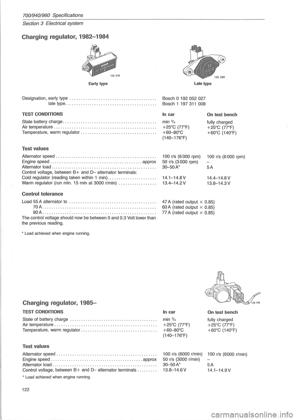
Charging regulator , 1982-1984
Early type Late type
Designation , early type . . . . . . . . . . . . . . . . . . . . . . . . . . . . . . . . . . . . . . . Bosch 0 192 052 027
late
type . . . . . . . . . . . . . . . . . . . . . . . . . . . . . . . . . . . . . . . . . Bosch 1 197 311 008
TEST COND IT IO NS
State battery charge ........................... ............ .. .
Air temperature
.......................... ................... .
Temperature ,
warm regulator ............................. .... .
Tes t values
Alternator speed ...... ...................................... .
Engine speed ..
..... .................................. approx
Alternator load ............ .............................. .... .
Control voltage, between B+ and D-alternator terminals:
Cold regulator
(reading taken within 1 min) .. ................... .
Warm regulator (run min. 15 min at 3000 r/min) ................ .
Co ntrol to le ra n ce
Load 55 A alternator to ........ ........... ... ................ .
70A ................................ .................. .
90A ........ .................................. ........ .
The
control voltage should now be between 0 and 0.3 Volt lower than
the previous reading .
• Load achieved when engine running .
Charging regulator , 1985-
TES T CO NDITION S
State of battery charge ........................ ............ .. .
Air temperature
............................................. .
Temperature, warm
regulator ............... .................. .
Tes t values
Alternator speed ............... ............................. .
Engine speed
............................. ............ approx
Alternator load .................. ............................ .
Control voltage, between B+ and D-alternator terminals ........ .
• Load achieved when engine running .
122
In car
min 3/4
+25°C (7rF)
+60-80°C
(140-176 °
F)
100 rls (6000 rpm)
50 rls (3000 rpm)
30-50A*
14.1-14.8V
13.4-14.2V
On tes t b ench
fully charged
+25°C (7rF)
+60°C (140 °F)
100 rls (6000 rpm)
5A
14.4-14.8 V
13.8-14.3 V
47 A (rated output x
0.85)
60 A (rated output x 0.85)
77 A (rated output x 0.85)
In c ar
min 3/4
+25°C (77 °F)
+ 60-80°C
(140-176 °
F)
On tes t be nch
fully charged
+25°C (7rF)
+60°C (140 °F)
100 rls (6000 r/min) 100 rls (6000 r/min)
50 rls (3000 r/min)
30-50A* 5A
13.8-14.6V 14.1-14 .9V
Page 129 of 168
70019401960 Specifications
Section 3 Electrical System
Group 35 Lighting
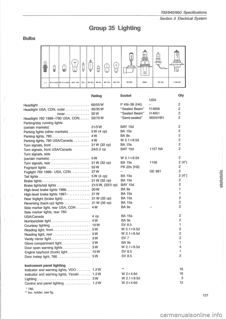
Bulbs
.~<
~ w W ~ ~ ffi 8 W
j At t ~ 'I lkU
.. W 2x4,6d W 2.1x9.5d BAY 15d VS 7 SV 8,5 BA9s BA 155 BA 155 GE B81 9004 PK 225 P 43t·38
( Rating Socket Qty
USA
Headlight ................... ........... 60/55W P
45t-38 (H4) 2
Headlight
USA, CON, outer .............. 35/35W "Sealed Beam" H4656 2
inner
.............. 50W "Sealed Beam" H4651 2
Headlight 760 1988--/780
USA, CON ...... 50/70W "Semi-sealed" 9004/HB1
2
Parking/day running
lights
(certain markets) 21/5W BAY 15d 2
Parking
lights (other markets) ............ 5W (4 cp) BA 15s 2
Parking lights, 780
...................... 4W BA 9s 2
Parking
lights, 780 USA/Canada .......... 4W W 2.1 x9.5d 2
Turn signals, front
...................... 21 W (32 cp) BA
15s 2
Turn signals, front USA/Canada 24/2.2
cp
BAY 15d 1157
NA 2
Turn signals,
side
(certain markets) .
...................... 5W W 2.1 x9.5d 2
Turn signals, rear ..
..................... 21 W (32 cp) BA
15s 1156 2
(4*)
Fog/spot
lights ....... .................. 55W PK 22s (H3) 2
Foglight 760 1988--
USA, CON ........... 27W GE 881 2 "' Tail lights .............................. 5W (4 cp) BA
15s 2
(4*) ' .... ,
Brake lights ............................ 21 W (32 cp) BA 15s 2 :':':1
Brake lights/tail
lights ................... 21/5 W, (3213 cp) BAY 15d 2 ':.:.: High-level brake lights 1986 .............. 20W BA 9s
High-level brake lights 1987-..........
.. 21W BA 15s
Rear foglight (brake
light) ................ 21 W (32 cp) BA
15s 2
Reversing (back-up)
lights ............... 21 W (32 cp) BA
15s 2
Side marker light, rear USA, CON ........ 4W BA
9s 2
Side marker
lights, rear 780
USA/Canada 4
cp
BA 15s 2
Numberplate
light ....................... 4W BA 9s 2
Courtesy lighting
....................... 10W SV 8.5
Reading
light, front. ..................... 5W W 2 .1 x 9.5d 2
Reading
l ight, rear ...................... 5W W 2.1 x 9.5d 2
Vanity mirror
light ....................... 3W SV 7 2
Glove compartment light. ................ 2W BA 9s
Door
open warning lights ................ 3W W 2.1 x 9.5d 4
Engine bay/boot (trunk)
light ............. 10W SV 8 .5 1
Ooor instep light, 780
................... 5W SV 8.5 2
Instrum
ent panel lighting
Indicator and warning lights, VDO ........ 1.2W ** 16
Indicator and warning lights, Yazaki ....... 1.2W W 2x4.6d 16
Lighting ............................... 3W W 2.1 x9.5d 3
Control and panel lighting ......
..... .... 1.2W W 2x4.6d 12
• 780. H Inc . holder. see fig . 127
)
Page 130 of 168
7001940;'960 Specifications
Section 3 Electrical System
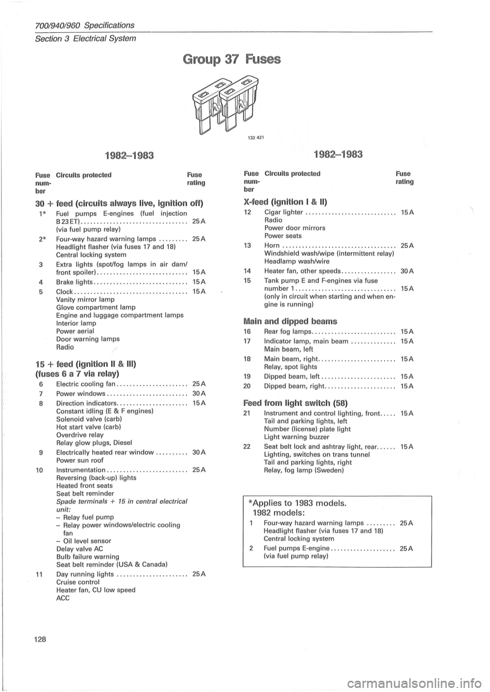
Group 37 Fuses
1982-1983
Fu se Circuits protected
num -
ber Fuse
rating
30 + feed (c ir cu its alw ays live, ig nition off)
1 * Fuel pumps E-engines (fuel injection
B23ET) ........................... ...... 25A (via fuel pump relay)
2* Four-way hazard warning lamps ........ . 25A Headlight flasher (via fuses 17 and 18) Central locking system
3 Extra
lights (spot/fog lamps in air dam/
4
5
front spoiler) ............................ 15A
Brake lights ............. ................ 15A
Clock .......................... ......... 15A Vanity mirror lamp
Glove compartment lamp Engine and luggage compartment lamps
Interior lamp
Power aerial Door warning lamps
Radio
15 + feed (ignition II & III)
(fu ses 6 a 7 via relay)
6 Electric cooling fan ...................... 25A
7 Power windows .................. ....... 30A
8 Direction indicators ...................... 15A Constant idling (E & F engines) Solenoid valve (carb)
Hot start valve (carb)
Overdrive relay
Relay glow plugs , Diesel
9 Electrically heated rear window. . . . . . . . .. 30 A
Power sun roof
10 Instrumentation ...................... , .. 25A Reversing (back-up) lights Heated front seats
Seat belt reminder Spade terminals + 15 in central electrical
unit:
-Relay fuel pump -Relay power windows/electric cooling
fan
-Oil level sensor Delay valve AC Bulb failure warning
Seat belt reminder (USA & Canada)
11 Day running lights ...................... 25A Cruise control
128
Heater fan, CU low speed
ACC
1982-1983
Fuse Circuits protected
num -
ber
X-feed (ign ition I & II)
Fuse rating
12 Cigar lighter ... ......................... 15A Radio
Power door mirrors
Power seats
13 Horn ................................ ... 25A Windshield wash/wipe (intermittent relay)
Headlamp wash/wire
14 Heater fan, other speeds. . . . . . . . . . . . . . . .. 30 A
15 Tank pump E and F-engines via fuse number 1 .............................. . (only in circuit when starting and when engine is running)
Ma in and dipped beams
16 Rear fog lamps ......... .................
17 Indicator lamp, main beam .............. Main beam, left
18 Main beam, right. ....................... Relay, spot lights
19 Dipped beam, left .......................
20 Dipped beam, right ......................
Feed from light switch (58 )
15A
15A
15A
15A
15A
15A
21 Instrument and control lighting, front ..... 15A Tail and parking lights, left Number (license) plate light Light warning buzzer
22 Seat belt lock and ashtray light, rear ...... 15A Lighting, switches on trans tunnel
Tail and parking lights, right Relay, fog lamp (Sweden)
* Applies to 1983 models.
1982 models:
Four-way hazard warning lamps ......... 25A Headlight flasher (via fuses 17 and 18) Central locking system
2
Fuel pumps E-engine .................... 25A (via fuel pump relay)