Page 17 of 34
Fiat 127 Internet Fan Club (http://fiat127.okruhy.cz) Fiat 127 - 1050
17/34
3.18 The valve depressions in the piston are adjece nt to
the cylinder head studs in the block 3.20 Torque tighten the big-end cap nuts
3.22A Firts fit outer rotor to the oil pump body… 3.22B …followed by the inner rotor
3.23 Measure the end clearance of the rotors with t he
pump face 3.24 Measure the outer rotor to body clearance…
Page 18 of 34
Fiat 127 Internet Fan Club (http://fiat127.okruhy.cz) Fiat 127 - 1050
18/34
3.25 …and the inner to outer rotor clearance 3.27A Fit the oil pump pressure relief valve plunge r and
spring…
3.27B …followed by the retainer plate and circlip 3.28 Refit the pump lower half body
3.29 Fit the oil pump to the crankcase 3.30 The oil tube is secured by a bracket to the ce ntre main
bearing cap with a bolt and washer
Page 19 of 34
 Fiat 127 - 1050
19/34
3.32 Fitting the crankshaft seal and carrier at fly")
Fiat 127 Internet Fan Club (http://fiat127.okruhy.cz) Fiat 127 - 1050
19/34
3.32 Fitting the crankshaft seal and carrier at fly wheel
and… 3.33 …and at the timing cover end
3.34 The timing indicator bracket is located behind the two
top bolts of the seal carrier 3.36 Fit the sump to the crankcase
on fine clearances and these should be checked
during assembly.
22 Fit the outer rotor to the pump body and then
fit the inner rotor (photos).
23 Lay an accurate straight edge across the
faces of the rotors and pump body and measure
the clearance with feeler gauges (photo).
24 Insert a feeler gauge between the outer rotor
and the pump body to measure the clearance
(photo).
25 Similarly insert a feeler gauge between the
inner rotor lobe tip and the outer rotor to
measure the clearance between the two (photo).
26 Compare the clearances with the tolerances
quoted in the Specifications to this Chapter. Any
excessive clearance could result in low oil
pressure, and as the inner and outer rotors are
matched pairs the only solution is a new or
reconditioned pump assembly. 27 Fit the oil pressure relief valve plunger to th
e
pump body followed in turn by the spring,
retainer plate and circlip (photos).
28 Lubricate the rotors with clean engine oil and
refit the pump lower half body and strainer
(photo).
29 With a new gasket, fit the assembled oil
pump to the crankcase block and secure with
the two long bolts (photo). Tighten to the
specified torque load.
30 Fit the oil tube to the crankcase securing it by
its bracket to the centre main bearing cap with
its retaining bolt. Tighten to the specified torque
load (photo).
Craknshaft oil seals and carriers-refitting
31 Clean the flywheel mounting spigot on the
end of the crankshaft and lubricate the
crankshaft seal with clean engine oil. Fit a new
gasket.
Page 20 of 34
Fiat 127 Internet Fan Club (http://fiat127.okruhy.cz) Fiat 127 - 1050
20/34
3.39 Fitting the auxiliary shaft… 3.40 …and its seal and carrier
3.42 This face of the pulley fits towards the shaft 3.43 Fit the belt tensioner bracket a new gasket to the
block …
3.44 …followed by the spring-loaded plunger… 3.45 …and then the tensioning wheel
Page 21 of 34
Fiat 127 Internet Fan Club (http://fiat127.okruhy.cz) Fiat 127 - 1050
21/34
3.46 The bevelled washer is fitted bevel outwards a nd is
followed by… 3.47 …the crankshaft toothed pulley
3.48A Valve guide oil seal 3.48B Inserting a valve followed by…
3.48C …the lower spring seat and springs… 3.48D …and upper spring seat
Page 22 of 34
Fiat 127 Internet Fan Club (http://fiat127.okruhy.cz) Fiat 127 - 1050
22/34
3.48E A magnet is useful for refitting the split co llets 3.48F After assembly a sharp tap on the valve stem will
help to bed the parts in
3.49A Use a small pointed tool to … 3.49B …prise out the vlave clearance adjusting shim
3.49C This shim is 4,15mm thick 3.49D Refit each tappet bucket with its shim to its vlave
Page 23 of 34
 Fiat 127 - 1050
23/34
32 Carefully ease the lip of the seal onto the")
Fiat 127 Internet Fan Club (http://fiat127.okruhy.cz) Fiat 127 - 1050
23/34
32 Carefully ease the lip of the seal onto the
spigot and secure the carrier with the bolts and
washers (photo).
33 Similarly clean the crankshaft at the timing
belt end and fit the seal and carrier. Retain by
the two bottom bolts (photo). 34 Put the timing
indicator bracket over the two top bolt holes in
the seal carrier and fit the two top bolts (photo).
Sump - refitting
35 Make sure that there are no remnants of the
old gasket on the sump flange and fit a new
gasket using a little grease to hold it in position .
Check that it is bedded down evenly all round
the flange.
36 Fit the sump to the crankcase. Put the load
spreading washers on each bolt and screw into
the crankcase (photo).
37 Tighten the bolts evenly to avoid warping the
flange.
Auxiliary shaft and seal - refitting
38 Clean the auxiliary shaft bearings and
lubricate with clean engine oil.
39 Insert the shaft into the crankcase bushes
and rotate the shaft to spread the oil (photo).
40 Lubricate the auxiliary shaft seal in its carrie r
and carefully ease the seal over the shaft spigot
(photo).
41 Fit the seal carrier retaining bolts and
washers and tighten.
Belt pulleys and tensioner - refitting
42 Fit the toothed pulley to the auxiliary shaft.
The recess in the pulley fits on the auxiliary shaf t
with the dowel on the shaft in the hole in the
pulley (photo). Fit the retaining bolt and washer
and partially tighten, as it will be necessary to
wait until the drivebelt has been fitted before
finally tightening this bolt. Alternatively, it is
possible to hold the auxiliary shaft carefully in a
vice, fit the seal and carrier to the shaft, follow ed
by the toothed pulley and its retaining bolt and
washer, and then tighten the bolt fully before
fitting the complete assembly to the block.
43 The belt tensioner bracket can now be fitted.
Clean off all traces of old gasket from the
bracket and block and use a new gasket on
assembly. Fit the retaining bolts and washers
and tighten (photo).
44 Insert the spring-loaded plunger assembly
into the tensioner bracket (photo).
45 The tensioning wheel in its carrier can now
be fitted. Put the top bolt and washer in first and
then bear down to compress the spring and fit the bottom bolt through the kidney-shaped slot.
Note that this latter bolt has an additional, large
washer against the wheel carrier. Temporarily
tighten the two bolts they will have to be
retightened after the belt has been fitted (photo).
46 If the key had previously been removed from
the pulley end of the crankshaft, clean the key
slot and refit the key. Then slide on the bevelled
washer, making sure that the bevel is on the
side away from the crankcase (photo).
47 Refit the crankshaft toothed pulley (photo).
Then the V-belt pulley can be refitted together
with its retaining nut and washer. Final
tightening of this nut can wait until the flywheel
has been fitted, when a 'gag' can be fitted to the
flywheel to hold the crankshaft whilst tightening
the nut - see Chapter 1, photo 23.2A.
Cylinder head and valve gear-reassembly
48 It is assumed that the valves will have
already been examined and renovated as
described in Chapter 1, Section 31. Follow the
procedure given in Chapter 1, Section 51 to
reassemble the valves, but note that new oil
seals should be fitted to this engine when the
valves have been inserted in the guides and
before the springs are fitted (photos).
49 Each tappet bucket contains a shim in the
head which is used to control the valve
clearance. Before assembling the buckets to
their valves, prise out each shim and take a note
of the thickness. This is etched on the lower face
of the shim and indicates the thickness in
millimetres to two decimal places. If the number
has worn off, use a micrometer to check the
shim thickness. Make a table showing each
valve by number and the thickness of shim on
assembly. Reassemble each shim to its bucket
and after lubricating with clean engine oil fit the
buckets to their respective valves (photos).
50 Lubricate the two camshaft bearings in the
cylinder head and carefully thread the camshaft
through the driving end hole and lower it onto its
bearings. The cams will rest on the tappet
buckets and the camshaft should now be turned
so that the two cams over No. 1 cylinder (driving
end) are pointing upwards (compression/firing
stroke). This is to reduce the bending load on
the camshaft as the two bearing halves are
being tightened down (photo).
51 Lubricate the camshaft bearing halves and fit
them to their respective studs in the head. Put
the steel bridge plates in position and fit the
washers and nuts (photo).
52 Tighten the four nuts a little at a time
Page 24 of 34
 Fiat 127 - 1050
24/34
progressively until the bearing halves meet.
53 Oil")
Fiat 127 Internet Fan Club (http://fiat127.okruhy.cz) Fiat 127 - 1050
24/34
progressively until the bearing halves meet.
53 Oil the camshaft seal and carefully fit it with
its carrier and a new gasket to the cylinder head
(photo).
54 Position the drivebelt guard backplate over
the camshaft seal carrier and fit the three bolts
and washers (photo). 55 Tighten the three bolts
retaining the backplate and seal carrier. Torque
load the four camshaft bearing securing nuts to
the specified setting.
56 Fit the camshaft toothed driving pulley with its
bolt and washer. Leave the final tightening until
the drivebelt is fitted (photo).
57 Check the valve clearances; the camshaft
can be turned by a spanner on the pulley
retaining bolt. Readjust any clearance if
necessary, as described later in this Section.
58 Owing to the small clearance between a
piston at TDC and the open valves during
exhaust/inlet overlap, it is imperative to get the
crankshaft and camshaft in their correct related
positions before turning the engine after fitting
the cylinder head. If this relationship is out then
serious damage could be done to the valves or
pistons by turning the crankshaft, as the pistons
will impinge on the valve heads. To avoid this
the following sequence should be observed. Set
the crankshaft as described in paragraph 59,
and the camshaft (before assembling the
cylinder head to the block) also as described in
paragraph 59. Fit the head to the block taking
care not to disturb the set positions and, finally,
fit the toothed drivebelt. Then the crankshaft can
be turned with no likelihood of damage.
59 Set the crankshaft by using a spanner on the
pulley retaining nut and aligning the mark on the
pulley with the long pointer on the timing
indicator bracket. Then set the camshaft by
aligning the hole in the camshaft pulley with the
cast ridge on the top of the camshaft seal carrier
just behind the toothed pulley (photo).
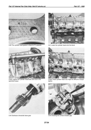
60 Fit a new cylinder head gasket with the word
ALTO upwards (photo). Do not use grease or
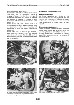
any other jointing compound. 61 Taking care not
to disturb the crankshaft or camshaft lower the
cylinder head onto the block (photo).
62 Fit the thick washers to the studs on the
manifold side of the block followed by the nuts.
Fit the bolts with their thick washers to the other
side of the block and screw the bolts and nuts
down to lightly compress the gasket. The bolts
and nuts must now be torque loaded by stages
(see Specifications) in sequence, to the
specified load and in the order shown in
Fig.13.3. This may present some difficulty as,
owing to the shape of the cylinder head, it is not
possible to get a socket spanner fitted to a
torque wrench over the cylinder head nuts.
These can be tightened using a ring or open-
ended spanner as an extension to the torque
wrench, but then, of course, the applied torque
will be different to the torque registered or set o n
the torque wrench. To overcome this a simple
calculation can be made so that a setting can be
established for the torque wrench which, with an
extension, will produce the specified torque
loading. This value varies with the ratio of t he
Fig. 13.3. 1049 cc engine cylinder head nut and bol t tightening sequence (Sec.3)


 Fiat 127 - 1050
17/34
3.18 The valve depressions in the piston are adjece")
 Fiat 127 - 1050
18/34
3.25 …and the inner to outer rotor clearance 3")
 Fiat 127 - 1050
20/34
3.39 Fitting the auxiliary shaft… 3.40 …and")
 Fiat 127 - 1050
21/34
3.46 The bevelled washer is fitted bevel outwards a")
 Fiat 127 - 1050
22/34
3.48E A magnet is useful for refitting the split")