Page 9 of 34
 Fiat 127 - 1050
9/34
Maximum run-out of driven plate linings 0.2 mm (0.008")
Fiat 127 Internet Fan Club (http://fiat127.okruhy.cz) Fiat 127 - 1050
9/34
Maximum run-out of driven plate linings 0.2 mm (0.008 in)
Travel of release flange, corresponding
to a pressure plate displacement of not less
than 0.067 in ~1.7 mm) 8.5 mm (0.3346 in)
Transmission
Synchromesh 1st and 2nd, Borg-Warner baulk ring type,
3rd and 4th, Porsche spring ring type
Gear ratios
First 3.910 : 1
Second 2.055 : 1
Third 1.348 : 1
Fourth 0.963 : 1
Reverse 3.615 : 1
Final drive ratio (C,L and CL) 4.071 : 1 (14/57)
Final drive ratio (Sport) 4.462 : 1 (13/58)
Overall ratios
Gears 1st 2nd 3rd 4th Reverse
C, L and CL 15.92 8.7 5.49 3.92 14.72
Sport 17.45 9.17 6.01 4.30 16.13
Electrical system
Alternator
Type (C, L and CL) Magneti Marelli AA 108-14V-33A
Type (Sport) Lucas 18ACR-A4V-45A
Maximum output (approx) 570 watts
Maximum current (approx) 40 amps (C, L and CL) 50 amps (Sport)
Cut-in speed at 12V and 20°C (68°F) 1050 to 1150 r pm (C, L and CL)
1100 to 1200 rpm (Sport)
Field winding resistance across slip rings at 20°C (68°F) 3.4 to 3.8 ohms (C, L and CL)
3.18 to 3.22 ohms (Sport)
Direction of rotation (drive end) Clockwise
Engine/alternator drive ratio 1.8 : 1
Alternator regulator (C, L and CL models)
Type Magneti Marelli RTT 110 AB
Alternator speed for adjustment 6000 rpm
Current for thermal balance 20 amps
Regulating voltage 14.2
+0.3
–0.2 volts
Page 10 of 34
 Fiat 127 - 1050
10/34
Lamps
Headlamps (C, L and CL)
Headlamps (Sport)")
Fiat 127 Internet Fan Club (http://fiat127.okruhy.cz) Fiat 127 - 1050
10/34
Lamps
Headlamps (C, L and CL)
Headlamps (Sport)
Brake and rear light
Turn indicators
Reversing lights
Parking lights
Number plate
Courtesy light
Boot light
Turn repeaters
Cigar lighter light
Instrument panel
Ignition warning
Turn indicator warning
Headlamp warning
Coolant temperature warning (L models)
Oil pressure warning
Fuel warning
Hazard warning
Sidelamp (out) warning (Sport only)
Brake warning (Sport only)
Heated rear window warning (Sport only)
40/45 watts
55/60 watts (Halogen)
5/21 watts
21 watts
21 watts
5 watts
5 watts
5 watts
5 watts
4 watts
4 watts
3 watts
3 watts
1.2 watts
1.2 watts
1.2 watts
1.2 watts
1.2 watts
1.2 watts
3 watts
1.2 watts
1.2 watts
Fuses
For fuse details (127 Special, L, C, CL and Sport) see Sections 23 or 24
Steering and suspension (Sport only)
Steering angles
Inner wheel 34° 50’
Outer wheel 32° 10’
Front wheel alignment (toe setting)
Laden 0.079 in (2.0 mm) toe-in to 0.079 in (2.0 mm) toe-o ut
Unladen 0.138 in (3.5 mm) to 0.217 in (5.5 mm) toe-in
Roadwheels
Size 4½ B x 13
Tyres 135 SR-13 or 155/70 SR-13
All 1049 cc models Ibf ft kgf m
Main bearing cap bolts 59 8.2
Engine mounting securing bolts 43 6
Cylinder head to block bolts and nuts:
1 st stage 30 4.1
2nd stage 45 6.2
Final stage 61 8.5
Manifold to head nuts 20 2.8
Connecting rod big-end nuts 38 5.2
Flywheel to crankshaft bolts 61 8.5
Driven gear (Plastic) to camshaft retaining bolt 87 12
Driven gear (steel) to camshaft retaining bolt 87 1 2
Camshaft cap nuts 14 2
Page 11 of 34
 Fiat 127 - 1050
11/34
Ignition distributor clamp nut 11 1.5
Oil pump to c")
Fiat 127 Internet Fan Club (http://fiat127.okruhy.cz) Fiat 127 - 1050
11/34
Ignition distributor clamp nut 11 1.5
Oil pump to crankcase bolts 13 1.8
Cylinder head outlet pipe bolt 16 2.2
Water pump/alternator drive pulley nut 101 14
Alternator bracket to crankcase bolt 20 2.8
Alternator to lower bracket bolt 36 5
Cylinder head upper bracket bolt 20 2.8
Alternator to upper bracket nut 36 5
Upper bracket securing bolt 13 1.8
Oil pressure switch 24 3.3
Coolant temperature switch 36 5
Spark plug 27 3.8
Sport models only
Engine
Flexible mounting to body (engine side) 65 9.0
Flexible mounting support (engine side to body)
18 2.5
Flexible mounting upper support to gearbox 18 2.5
Engine crossmember to body 18 2.5
Flexible mounting support nut (gearbox side) 18 2.5
Flexible mounting support bolt to body
(gearbox LH side) 65 9.0
Steering and suspension
Steering wheel retaining nut 22 3.0
Front wheel bearing ring nut 44 6.0
Front wheel hub nut 160 22.0
Roadwheel bolts 64 8.8
Front suspension track control arm to body 20 2.7
Front suspension balljoint to hub carrier 40 5.5
Rear wheel hub nut 160 22
Transmission
Starter motor bolt to bellhousing lower support 18 2.5
Gear selector shaft nut 18 2.5
Upper gear lever relay lever 22 3.0
Idler support securing nut 18 2.5
Differential case flange to gearbox housing 18 2.5
Page 12 of 34
 Fiat 127 - 1050
12/34
3. Engine
1049 cc engine - general
1 This engine")
Fiat 127 Internet Fan Club (http://fiat127.okruhy.cz) Fiat 127 - 1050
12/34
3. Engine
1049 cc engine - general
1 This engine is of overhead camshaft design,
using shims for valve clearance adjustment. The
crankshaft is supported in five main bearings,
the centre one incorporating the thrust washers
which control crankshaft endfloat.
2 An auxiliary shaft, driven by the toothed
camshaft belt, is used to drive the distributor and
the fuel pump. 3 Most major engine components
can be removed while the engine is in the car,
but operations on the crankshaft, main bearings
and flywheel can only be carried out after the
engine has been removed.
4 Engine removal and subsequent dismantling
follows closely the information given for the
overhead valve engine in Chapter 1, but the
following sequence for complete engine
dismantling is recommended:
(a) Engine ancillaries (alternator, fuel pump, distributor)
(b) Timing belt cover
(c) Water pump
(d) Timing belt tensioner and belt
(e) Manifolds
(f) Cylinder head complete with camshaft
(g) Crankshaft pulley
(h) Auxiliary shaft sprocket
(i) Sump
(j) Oil pump and auxiliary shaft
(k) Connecting rods and pistons
(l) Flywheel and crankshaft oil seal carriers
(m) Crankshaft and main bearings
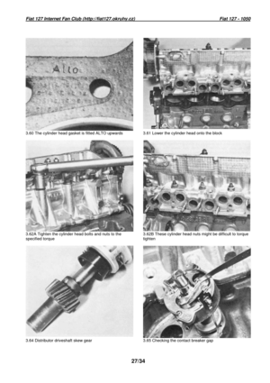
5 If the cylinder head is to be dismantled, before
withdrawing the camshaft, have a suitably divided
container ready so that the valve clearance
adjusting shims can be extracted and kept in strict
originally installed order together with their
appropriate valves, springs etc.
6 All engine parts must be thoroughly cleaned
and examined as explained in Chapter 1. Where
required, all defective parts should be renewed
before reassembly starts.
Crankshaft – refitting
7 Fit the main bearing shells to their seats in the
crankcase after making sure that both shells and
seats are spotlessly clean and dry (photos).
8 With a light smear of grease, fit the two half
thrust washers each side of the centre bearing
with the oil grooves in each washer facing away
from the bearing shell (photo).
9 Using clean engine oil lubricate the bearing
shells and crankshaft main bearing journals
(photo).
10 Carefully lower the crankshaft into its bearings
in the crankcase after making sure that it is the
right way round. Spin the shaft to distribute the o il
(photo).
11 Fit the clean and dry bearing shells to the main
bearing caps. Oil the bearing face and fit the
bearing caps to the crankcase. Make sure that
each cap is fitted to its own location by checking
the groove marks in the base, and that each cap
is the right way round. This is achieved when the
axial locating tags in each half bearing shell butt
on the same side (photos).
3.7A Thoroughly clean the bearing shells and seats
before
assembly 3.7B Note that central bearing shell has no oil gro ove but all
shell are axially located by an offset tag
Page 13 of 34
Fiat 127 Internet Fan Club (http://fiat127.okruhy.cz) Fiat 127 - 1050
13/34
13.1. 1049 cc engine, longitudinal section (Sec.3 )
Page 14 of 34
Fiat 127 Internet Fan Club (http://fiat127.okruhy.cz) Fiat 127 - 1050
14/34
13.2. 1049 cc engine, cross section (Sec.3)
(The engine is installed inclined 6°rearwards)
Page 15 of 34
 Fiat 127 - 1050
15/34
3.8 The half thrust washers are fitted each side of")
Fiat 127 Internet Fan Club (http://fiat127.okruhy.cz) Fiat 127 - 1050
15/34
3.8 The half thrust washers are fitted each side of
the
centre bearing
3.9 Oil the bearings and crankshaft journals…
3.10 … and then fit the crankshaft into the crankca se 12 Refit the main bearing cap bolts and screw
them up fingertight. Spin the crankshaft and, if
all is well, tighten the bolts to the specified
torque load and turn the crankshaft again to
check freedom of rotation (photo).
13 Measure the crankshaft endfloat with feeler
gauges. If this exceeds the specified tolerance,
oversize thrust washers will have to be fitted.
Pision rings - refitting
14 Follow the procedure given in Chapter 1,
Section 42.
Pistons and connecting rods–reassembly
15 Follow the procedure given in Chapter 1,
Section 43 (photo).
Pistons – refitting
16 Follow the procedure given in Chapter 1,
Section 44.
17 Note that the connecting rods in the 1049 cc
engine have two oil jet holes leading from the
big-end bearing (photo).
18 When the piston is correctly fitted it will have
the valve depressions adjacent to the side of the
block with the cylinder head studs in (photo). C
onnecting rods to crankshaft-
r
eassembly
19 Follow the procedure given in Chapter 1,
Section 45.
20 Torque load the big-end cap nuts to the
reading quoted in the Specifications of this
Chapter 13 - it is different from the value quoted
for the 903 cc engine (photo).
Oil pump - reassembly
21 The oil pump fitted to the 1049 cc engine is a
Hobourn-Eaton rotor type of pump which is quite
different from the gear pump fitted to the 903 cc
engine. It consists of a four lobed rotor rotating
in a five slotted outer rotor which is mounted
eccentrically to the inner rotor. As the inner roto r
rotates the outer rotor is driven round, and the
spaces between the lobes on the inner rotor and
the slots in the outer rotor increase and
decrease once per revolution. The increasing
spaces are connected to the pump inlet and
cause oil to be drawn into the pump. The
decreasing spaces connect with the pump outlet
through which the oil is forced to feed the
engine. A springloaded relief valve in the outlet
of the pump vents excessive oil pressure into
the sump. The efficiency of the pump depends
Page 16 of 34
Fiat 127 Internet Fan Club (http://fiat127.okruhy.cz) Fiat 127 - 1050
16/34
3.11A Fit the bearing shell ti the main bearing cap s… 3.11B …and then fit caps to the crankcase after oil ing the
shells
3.11C Ensure that each cap is the right way round i n its
own location with the one with four marks at the fl ywheel
end of the crankcase 3.12 Tighten main bearing cap bolts with a torque w rench
3.15 Piston and connecting rod assembly 3.17 One of the oil jet holes in the big-end – the other is on
the other side of the rod


 Fiat 127 - 1050
13/34
13.1. 1049 cc engine, longitudinal s")
 Fiat 127 - 1050
14/34
13.2. 1049 cc engine, cross section (")
 Fiat 127 - 1050
16/34
3.11A Fit the bearing shell ti the main bearing cap")