1982 Citroen CX battery
[x] Cancel search: batteryPage 134 of 394

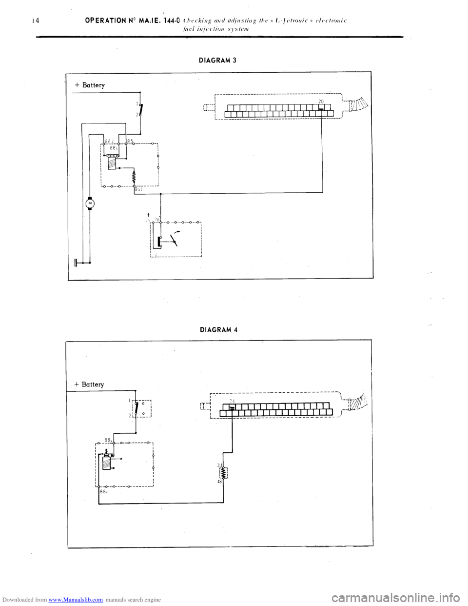
Downloaded from www.Manualslib.com manuals search engine DIAGRAM 3
+ Battery
:------------ ____ -----_---------- -------- -A---\,
+fi ,c
i!J &J
/---I - 0
___,’
DIAGRAM 4
Page 135 of 394

Downloaded from www.Manualslib.com manuals search engine Op. MA.IE 444-O 15
3. Fuel pump feed ( with engine running ) : ( DIAGRAM 3 )
- Disconnect the E.C.U.
- Disconnect from the air-flow sensor the air hose to the butterfly housing
- Switch on the ignition:
- Actuate the air-flow sensor flap by hand’ when the petrol pump contact closes the pump should be heard
working.
If not, test the circuit using a
battery operated ohmmeter, without forgetting to test between terminal G 36 ))
on the air-flow sensor and terminal H 20 .)) on the E.C.U. for continuity ( The 2nd terminal is not connected
to the E.C.U. ).
- The resistance between terminals (( 86 b H and G 85 )) on the relay box f //j/nor thc~ I~./I. h<~ntllnr~tp ) must be
between 52 and 78 12.
P 4. Supplementary air control ( DIAGRAM 4 )
4
c
5
6
- Disconnect the E.C.U.
-E
? - Check that the supplementary air control is properly connected ( arrow on the casing )~
In
If it is fitted the wrong way round. the port may be blocked.
- The resistance between terminals (( 34 1, and (( 48 )) on the- supplementary air control must be 50 Q approx-
- Visual checking the port on the supplementary air control must be open when the engine is cold, and closed
when the engine temperature is above 60” C
- With the engine cold. if the air pipe to the supplementary air control is flattened the engine rpm must decrease.
With the engine warm, if the air pipe is disconnected, the engine must accelerate.
Page 141 of 394

Downloaded from www.Manualslib.com manuals search engine DIAGRAM 9
+ Battery DIAGRAM l-0
1
i -
er
L----.
Page 143 of 394

Downloaded from www.Manualslib.com manuals search engine 11. Switch on throttle butterfly spindle ( maximum power function ) ( DIAGRAM 11 )
- Disconnect the E.C.U.
- Using a battery operated ohmmeter, check there is no resistance between terminals (( 3 H and (( 18 )) of the
multiple connector board, with the accelerator pedal fully depressed
t 12. E.C.U. : ( DIAGRAM 12) +
s
*
i :
2 - Visually check the condition of the terminals ( male connectors on the E-C U., and female connectors
on the multiple connector socket ).
- With the engine running, tap lightly on the E.C.U., to detect any possible defect in the soldering ( dry
joints ).
Page 158 of 394

Downloaded from www.Manualslib.com manuals search engine OPERATION No MA. 210-O : (.h(~~-ki/lg n~lc/ c~tlj~~s/irtg the igrlitiorl Op. MA. 210-O 3
1. Checking the condition of the contacts :
Check the voltage drop across the contacts ( contacts closed ) under a voltage of 12 volts. using a test-bench.
The voltage drop should be 0.2 volts max.
I
2. Checking the centrifugal advance curve :
a) Note the advance in stages for steadily increasing engine speeds from 0 to 3000 rpm. and for steadily
decreasing engine speeds from 3000 rpm to 0, t~/~kjj/$ SII~L’
the irirwasc, or d~,rrc~as~’ is c-o~~ti~ootl.5.
These points must fall within the shaded area of the curve.
b) To a certain extent. it is possible to correct the advance curve, by altering the tension of the springs for
the centrifugal weights To obtain this condition, slightly bend (
iv t/1(, np1)ro/)riotc, ciirectioll J the securing
brackets for the springs, or replace them.
IY NOTE : If luminous spots are produced outside the four normal positions at speeds under 3000 rpm. make
5 sure the contact points are clean and if necessary make sure the test-bench battery is fully charged. before
U replacing the contact-breaker unit. the spring of which may have weakened.
7
co
m
r 3. Checking the spark regularity :
2
Whatever the speed of rotation, the angular difference of the four opening positions of the points must n.ot
3 exceed lo I 21n.xint~lm r/In/ oj distributor : 3250 I./)NI. c,.vcc,pt I)l’(.lit,t.tt~K 525 06X A : 2750
r/m 1,
c
E
!i
a
z 4. Ch k’ ec rng and adjusting the dwell angle :
Run the distributor at a steady speed, and check that the dwell angle is equal ;o 55’ ? 2”30’. If this is not the
case, adjust the contact breaker to obtain this condition.
5. Checking the ignition condenser :
With the contact points open. measure the capacity of the condenser; This value must be 0.30 i 0.03 wF.
If this is not the case. replace the condenser.
6. Check the vacuum advance curve :
This check is carried out at a constant rpm of 200, with no centrifugal advance.
Check the points of the increasing curve. and the decreasing curve. If the vacuum capsule has n hathcr.
it will be necessary to blank it off during this check.
Page 289 of 394

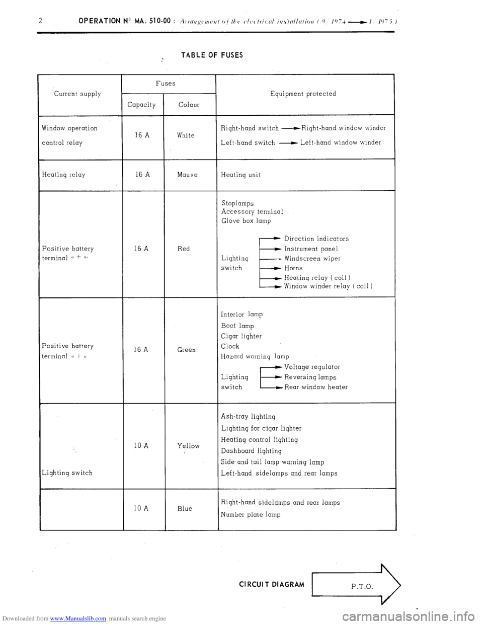
Downloaded from www.Manualslib.com manuals search engine TABLE OF FUSES
Current supply
findow operation
ontrol relay Fuses
Equipment protected
Capacity Colour
Right-hand switch -Right-hand window winder
16 A White
Left-hand switch - Left-hand window winder
Ieating relay 16 A Mauve Heating unit
Stoplamps
Accessory terminal
Glove box lamp
‘ositive battery
erminal (( + )). 16
A Red Direction indicators
E Instrument panel
Lighting -- Windscreen wiper
switch Horns
Heating relay ( coil )
Window winder relay ( coil )
‘ositive battery
erminal (( t 1) 16 A Green Interior lamp
Boot lamp
Cigar lighter
Clock
Hazard warning lamp
Lighting
switch
E
Voltage’ regulator
Reversing lamps
Rear window heater
Ash-tray lighting
10 A Yellow Lighting for cigar lighter
Heating control lighting
Dashboard lighting
,ighting switch Side- and tail lamp warning lamp
Left-hand sidelamps and rear lamps
10 A Blue Right-hand sidelamps and rear lamps
Number plate lamp Cl RCUI T DIAGRAM
r>
Page 292 of 394

Downloaded from www.Manualslib.com manuals search engine OPERATION No MA. 510-00 : \m//l‘!yc~tl/ <‘,/I 0 t Ih<’ <‘It,< Ir.itnl iusrtlllnliritt Op. MA. 510-00 3
f 0 lO7i-l,‘1975 )
DESCRIPTION OF THE COMPONENTS
!ep. Description and Position Rep. ‘D escription and Position
1
Right hand sidelamp ...... 74 51
Flasher unit .. ....... 21
Front right hand direction indicator ..... 21 52 Lighting and starter switch .... .4 8’44- 61
2 Right-hand headlamp Main beam .. 78 5.3
76 54 Petrol gauge rheostat ........ 25
Dipped beam
Right hand window winder control switch
3 Right~hand horn ............ 42
( O/)liWlNl J ................. 51
4 Left-hand horn ...
41 55 Heating control illumination f ~///io~n/) .. 68
5 Left-hand headlamp : Main beam ....... 77 56
Left hand window winder switch ( O/JI~OII~/~~~
Dipped beam ...... 75 57
Heated rear window switch Op/io~nl j ...... 14
6 Front left-hand direction indicator ... 16 58
Lightinq switch unit ............. ........... 72
Front left hand sidelamp ................. 69
Speedometer and tachometer lighting
8 Electric fan thermal switch .................. 59
rheostat ....... ...... .................... 28 10
Electric fan .......
58 59 Instrument panel : 11
Starter ...... ... .............. .......... 3
Thermal voltmeter and illumination .. 26-28 12
Alternator ............................ ........ 5 13 Petrol gauge and illumination ............ 25-69
Ignition coil ... ......... .............. 61 14
Speedometer and tachometer lighting 28
High tension sensor ....................... 64
Clock and clock illumination ....... 1667 15
Compressor for horn ............ ..... ...... 43
Heated rear window warning lamp ....... 15 16
Compressor relay ................... ..... 43
Headlamp dipped beam warning lamp ... 75 17
Battery ............. .... .. 1
Brake pad wear warning lamp .......... 27 18
Voltage regulator ......................... 6
Oil temperature warning lamp ............ 35
19
HT sensor for No. 1 cylinder ........... 64
Coolant temperature warning lamp ....... 29 20
Distributor ..................... ...........
61 Emergency stop warning lamps 32” 34
21
Windscreen washer pump ............. 36
Hydraulic pressure warning lamp ...... 31 22
Plug for diagnostic operations ............. .65
Warning lamp for hazard warning.. ...... 17 23
Engine oil pressure switch .............. .. 34
Sidelamp warning lamp ................... 70 24
Idle cut-off ....................... .60
Direction indicators warning lamp ........... 23 25
Engine oil temperature switch ........... 35
Headlamp main beam warning lamp ... 77 26
Enqine coolant temp. switch ... 30 60 Left-hand control panel : 27
Top dead centre sensor ........................ 64 Direction indicator and hazard warning 19 28
Reversing lamp switch ........................ 8
- Horns .................................... 41 30
Window winder control relay( Optior~nl ) .. ..4 9
Windscreen wiper motor ............... 38-39 31
Heating relay ............ ..................... 45
- Windscreen washer pump .......... . .......... 37 32
Electric fan relay ................................ 58 61
Rear right-hand lamp cluster 33
Front right-hand brake unit ................. 28
- Rear lamp ............................................... 73 34
Windscre,en wiper motor ........................ 38
- Stoplamp ............. .....
............ 53
35
Blower motor ............ .............................. 45
Direction indicator ................................... 19 36
Hydraulic pressure switch ...................... . 32
- Reversing lamp ..................................... 9 37
Stoplamp switch.. ......................................... 53 62
Boot lamp ................................................. 12 38
Fuse boxes ..... 8-44-45-49-69-72 63 Rear window heating element ................... 14 39
Front left-hand brake unit .......................... 26 64
Right-hand number plate lamp ................. 72 41
Front right-hand door switch ................... 11 65
Left-hand number plate lamp ................... 70 42
Right-hand window winder motor f Optiollal) 51 66
Boot lamp switch ........................................ 12 43 Glove box
lamp ...................................... 51 67 Rear left-hand .lamp cluster 44
Front left-hand door switch ........ .......... 10 - Rear lamp ................................................ 71 45
Left-hand window winder motor (Oplio~fll) 47 s Stoplamp ........................................... 52 46
Interior lamp ................................................. 10
- Direction indicator lamp ..................... 18 47
Cigar lighter and illumination ............... .13-67
- Reversing lamp .................................... 8 48
Accessory plug ..... ... .......................... .... 50
49
Ashtray illumination ,., ... ................ 66 DESCRIPTION OF THE WIRING HARNESS
lot marked :
Front harness co Compressor harness AR
Rear harness C Boot harness
M Engine harness PC
Boot lid harness LG
Window operation D Fault finding harness ( Diagnostic) TB
Instrument panel harness FV Flying lead
Page 297 of 394

Downloaded from www.Manualslib.com manuals search engine TABLE OF FUSES
Supply to
eater unit relay Fuse
Circuits protected
Rating Colour
16 Amps Mauve Heater unit
S toplamps
Accessory terminal
Glove box lightinq
Positive terminal
of battery u + )) 16 Amps Red
E Direction indicators
Ignition Windscreen wipers and washers
switch Horns
Heater relay windinq
Window-winder relay winding
Rheostat -speedometer lighting
Warning lamp panel ( Battery
meter ( Thermal voltmeter-- Brake pad wear warning
lamp - Fuel gauge - Oil pressure warning lamp -
Hydraulic fluid pressure warning lamp-Water temp.
warning lamp )
16 Amps Green Interior lamp
Boot lamp
Cigar-lighter
Clock
Hazard warning lamps
E Voltage regulator
Iqnition Reversing lamps
switch
Rear window heating element
Handbrake warning lamp
Window winder relay 16 Amps White R.H. Switch 0 R.H. window winder
L.H. Switch- L.H. window winder
Lighting
Switch 10 Amps Yellow Ashtray lighting
Cigar lighting
Heater controls lighting
Instrument panel lighting Clock
E Battery meter
Odometers
Sidelamp warning
L.H. sidelamps, front and rear 1 amp
Lighting
Switch 10 Amps Blue R.H. sidelamps, front and rear
Number-plate lamp CIRCUIT DIAGRAM
>
P.T.O.