1982 CHEVROLET CAMARO clock
[x] Cancel search: clockPage 724 of 875

GM – CAMARO 1982-1992 – Repair Guide (Checked by WxMax) 724
•
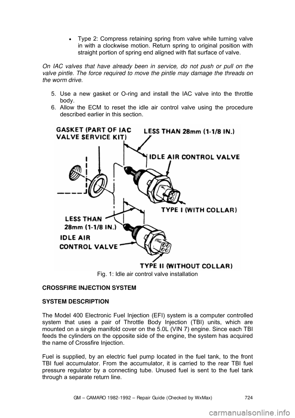
Type 2: Compress retaining spring from valve while turning valve
in with a clockwise motion. Return spring to original position with
straight portion of spring end aligned with flat surface of valve.
On IAC valves that have already been in service, do not push or pull on the
valve pintle. The force required to move the pintle may damage the threads on
the worm drive.
5. Use a new gasket or O-ring and install the IAC valve into the throttle body.
6. Allow the ECM to reset the idle air control valve using the procedure
described earlier in this section.
Fig. 1: Idle air control valve installation
CROSSFIRE INJECTION SYSTEM
SYSTEM DESCRIPTION
The Model 400 Electronic Fuel Injection (EFI) system is a computer controlled
system that uses a pair of Throttle Body Injection (TBI) units, which are
mounted on a single manifold cover on t he 5.0L (VIN 7) engine. Since each TBI
feeds the cylinders on the opposite side of the engine, the system has acquired
the name of Crossf ire Injection.
Fuel is supplied, by an electric fuel pum p located in the fuel tank, to the front
TBI fuel accumulator. From the accumulator, it is carried to the rear TBI fuel
pressure regulator by a c onnecting tube. Unused fuel is sent to the fuel tank
through a separate return line.
Page 729 of 875

GM – CAMARO 1982-1992 – Repair Guide (Checked by WxMax) 729
17. Check the throttle position sensor voltage and adjust if necessary.
18. Perform the Minimum Idle and Thro
ttle Valve Synchronization adjustment
procedures.
INJECTOR REPLACEMENT
The removal and installation procedures fo r the Crossfire injection system's fuel
injector is identical to the Throttle Bo dy Injection (TBI) system. Please refer to
the TBI fuel injector procedures earlier in this repair guide.
ADJUSTMENTS
PRELIMINARY ADJUSTMENTS
The preliminary adjustments are performed if tampering with the idle speed or
synchronization is evident and when either of the throttle bodies or the manifold
cover have been replaced. They must be performed BEFORE the Minimum Idle
and Throttle Valve Synchronizing procedure.
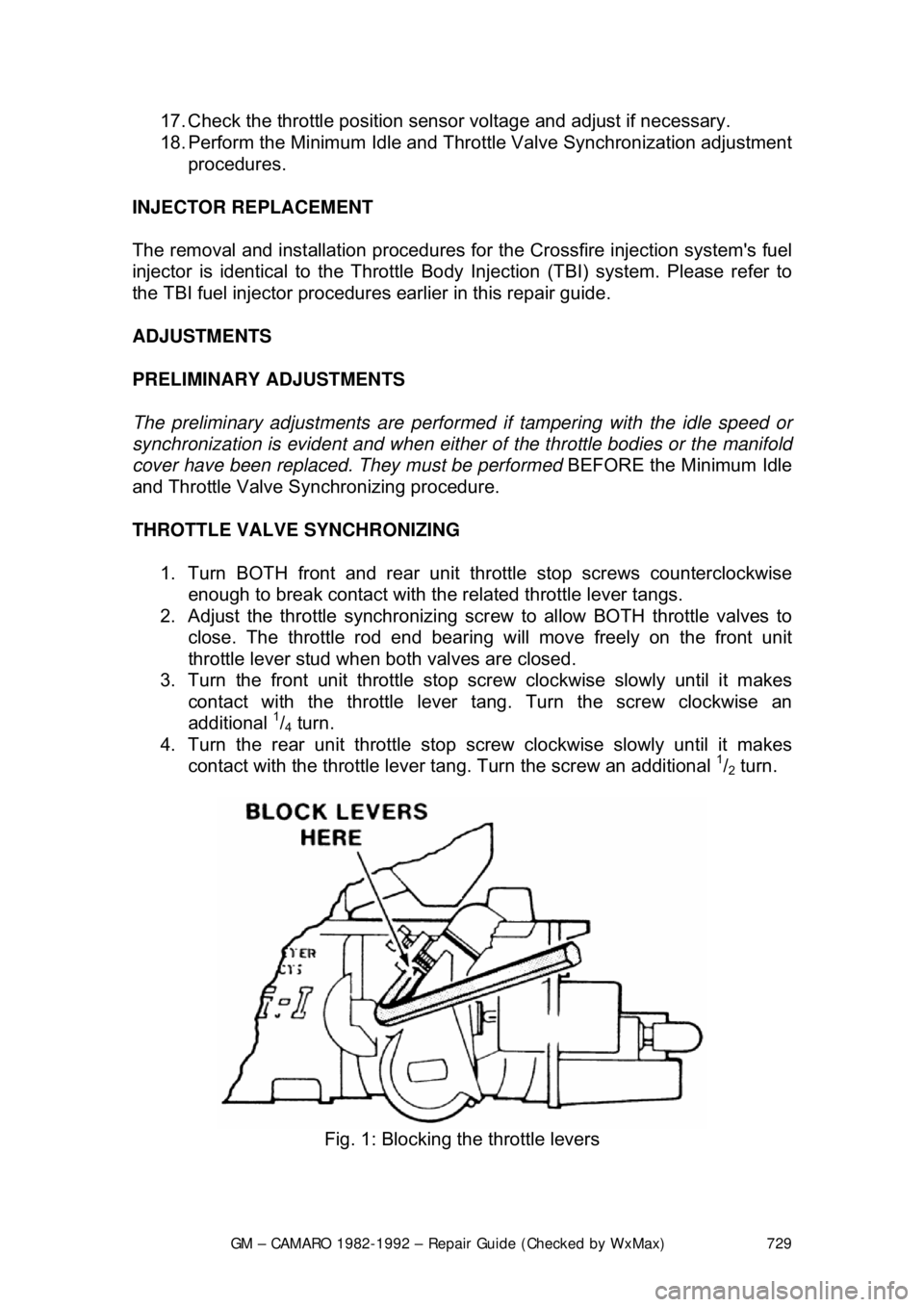
THROTTLE VALVE SYNCHRONIZING
1. Turn BOTH front and rear unit throttle stop screws counterclockwise enough to break contact with the related throttle lever tangs.
2. Adjust the throttle synchronizing scr ew to allow BOTH throttle valves to
close. The throttle rod end bearing w ill move freely on the front unit
throttle lever stud when both valves are closed.
3. Turn the front unit th rottle stop screw clockwise slowly until it makes
contact with the throttle lever tang. Turn the screw clockwise an
additional
1/4 turn.
4. Turn the rear unit throttle stop screw clockwise slowly until it makes
contact with the throttle lever t ang. Turn the screw an additional
1/2 turn.
Fig. 1: Blocking the throttle levers
Page 751 of 875

GM – CAMARO 1982-1992 – Repair Guide (Checked by WxMax) 751
13. Lubricate a new outlet tube 0-ring and in
stall it on the end of the tube.
14. Connect the regulator base to the fuel outlet tube, then to the fuel rail.
15. Finger-tighten the base-to-rail screw.
16. Install the pressure regulator br acket. Finger-tighten the screws only.
17. Lubricate a new rear crossover tube O-ring and install it on the end of the
tube.
18. Install the rear crossover tube to the regulator base.
19. Install the crossover tube reta iner and finger-tighten the screw.
20. Tighten all attaching screws to 44 inch lbs. (5 Nm).
21. Install the fuel rail assembly.
22. Temporarily connect the negative battery cable. a. With the engine OFF and the igniti on ON, check for fuel leaks.
b. Disconnect the negative battery cable.
23. Install the intake plenum and runners.
24. Connect the negative battery cable.
IDLE AIR CONTROL VALVE
REMOVAL & INSTALLATION 1. Unplug the electrical connector from idle air control valve.
2. Remove the idle air control valve.
To install: 3. Before installing the idle air contro l valve, measure the distance that the
valve is extended. Measurement s hould be made from the motor housing
to the end of the cone. It should not exceed 28.5mm (1
1/8 in.), or damage
to the valve may occur when installed.
4. On 1985-1992 models, identify the replacement IAC valve as being
either Type 1 (with collar at electric terminal end) or Type 2 (without
collar). If measuring distance is great er than specified above, proceed as
follows:
• Type 1: Use finger pressure to slowly retract the pintle.
• Type 2: Compress retaining spring from valve while turning valve
in with a clockwise motion. Return spring to original position with
straight portion of spring end aligned with flat surface of valve.
On IAC valves that have already been in service, do not push or pull on the
valve pintle. The force required to move the pintle may damage the threads on
the worm drive.
5. Use a new gasket or O-ring and install the IAC valve into the throttle body.
6. Allow the ECM to reset the idle air control valve using the procedure
described earlier in this section.
Page 761 of 875

GM – CAMARO 1982-1992 – Repair Guide (Checked by WxMax) 761
MAINTENANCE OR REPAIR?
Maintenance includes routine inspecti
ons, adjustments, and replacement of
parts which show signs of normal wear . Maintenance compensates for wear or
deterioration. Repair implies that someth ing has broken or is not working. A
need for a repair is often caused by lack of maintenance. for example: draining
and refilling automatic transmission fl uid is maintenance recommended at
specific intervals. Failure to do this can shorten the life of the
transmission/transaxle, requiring very expen sive repairs. While no maintenance
program can prevent items from eventually breaking or wearing out, a general
rule is true: MAINTENANCE IS CHEAPER THAN REPAIR.
Two basic mechanic's rules should be mentioned here. First, whenever the left
side of the vehicle or engine is refe rred to, it means the driver's side.
Conversely, the right side of the vehi cle means the passenger's side. Second,
screws and bolts are removed by turn ing counterclockwise, and tightened by
turning clockwise unless specifically noted.
Safety is always the most important rule. Constantly be aware of the dangers
involved in working on an automobile and take the proper precautions. Please
refer to the information in this se ction regarding SERVICING YOUR VEHICLE
SAFELY and the SAFETY NOTICE on the acknowledgment page.
AVOIDING THE MOST COMMON MISTAKES
Pay attention to the instructions prov ided. There are 3 common mistakes in
mechanical work:
1. Incorrect order of assembly, di sassembly or adjustment. When taking
something apart or putting it toget her, performing steps in the wrong
order usually just costs you ex tra time; however, it CAN break
something. Read the entire proc edure before beginning. Perform
everything in the order in which the instructions say you should, even if
you can't see a reason for it. When you' re taking apart something that is
very intricate, you might want to draw a picture of how it looks when
assembled in order to make sure you get everything back in its proper
position. When making adjustments, per form them in the proper order.
One adjustment possibly will affect another.
2. Overtorquing (or undertorquing). While it is more common for overtorquing to cause damage, undertorquing may allow a fastener to
vibrate loose causing serious dam age. Especially when dealing with
aluminum parts, pay attention to tor que specifications and utilize a torque
wrench in assembly. If a torque figure is not available, remember that if
you are using the right tool to perfo rm the job, you will probably not have
to strain yourself to get a fast ener tight enough. The pitch of most
threads is so slight that the te nsion you put on the wrench will be
multiplied many times in actual fo rce on what you are tightening.
There are many commercial products avai lable for ensuring that fasteners won't
come loose, even if they are not torqued just right (a very common brand is
Page 791 of 875

GM – CAMARO 1982-1992 – Repair Guide (Checked by WxMax) 791
3. Clean all dirt from
the area around the cover. Re move the bolts retaining
the cover to the housing. Pry the co ver from the differential housing and
allow the fluid to drain into the catch pan.
To install: 4. With the cover and housing washed free of oil and gasket material, apply sealer to the mating surfaces.
5. Using a new gasket, install the cove r and torque the bolts to 20 ft. lbs.
(27 Nm) in a clockwise pattern to in sure uniform draw on the gasket. Fill
the differential with fluid through the fi ll plug and add limited slip additive,
as required.
6. Install the parking brake cable guides, if removed.
7. The fluid level shou ld reached a level within
3/8 in. (10mm) of the filler
plug hole. Replace the filler plug. Low er the car and inspect for leaks.
COOLING SYSTEM
CAUTION - When draining the c oolant, keep in mind that cats and dogs are
attracted by the ethylene gl ycol antifreeze, and are quite likely to drink any that
is left in an uncovered container or in puddles on the ground. This will prove
fatal in sufficient quantity. Always drai n the coolant into a sealable container.
Coolant should be reused unless it is c ontaminated or several years old (in
which case it should be taken to a recycli ng facility such as a service station).
FLUID RECOMMENDATIONS
When adding or changing the fluid in the system, create a 50/50 mixture of high
quality ethylene glycol antifreeze and water.
LEVEL CHECK
Fig. 1: Fluid level marks on the cool ant recovery tank. With a warm system,
coolant level should be just below the FULL HOT mark on tank.
Page 794 of 875

GM – CAMARO 1982-1992 – Repair Guide (Checked by WxMax) 794
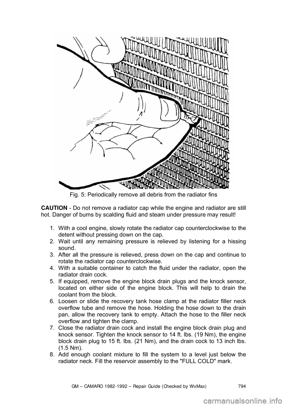
Fig. 5: Periodically remove all debris from the radiator fins
CAUTION - Do not remove a radiator cap wh ile the engine and radiator are still
hot. Danger of burns by scalding fluid and steam under pressure may result!
1. With a cool engine, slowly rotate t he radiator cap counterclockwise to the
detent without pressing down on the cap.
2. Wait until any remaini ng pressure is relieved by listening for a hissing
sound.
3. After all the pressure is relieved, press down on the cap and continue to
rotate the radiator cap counterclockwise.
4. With a suitable container to catc h the fluid under the radiator, open the
radiator drain cock.
5. If equipped, remove the engine blo ck drain plugs and the knock sensor,
located on either side of the engine block. This will help to drain the
coolant from the block.
6. Loosen or slide the recovery tank hos e clamp at the radiator filler neck
overflow tube and remove the hose. Holding the hose down to the drain
pan, allow the recovery tank to empty. Attach the hose to the filler neck
overflow and tighten the clamp.
7. Close the radiator drain cock and install the engine block drain plug and
knock sensor. Tighten the knock sensor to 14 ft. lbs. (19 Nm), the engine
block drain plug to 15 ft. lbs. (21 N m), and the drain cock to 13 inch lbs.
(1.5 Nm).
8. Add enough coolant mixture to fill the system to a level just below the
radiator neck. Fill the reservoir a ssembly to the "FULL COLD" mark.
Page 847 of 875

GM – CAMARO 1982-1992 – Repair Guide (Checked by WxMax) 847
DISARMING
1. Turn the steering wheel to align the w heels in the straight-ahead position.
2. Turn the ignition switch to the LOCK position.
3. Remove the SIR air bag fuse from the fuse block.
4. Remove the left side trim panel and disconnect the yellow 2-way SIR
harness wire connector at the bas e of the steering column.
To enable system: 5. Turn the ignition switch to the LOCK position.
6. Reconnect the yello w 2-way connector at the base of the steering
column.
7. Reinstall the SIR fuse and the left side trim panel.
8. Turn the ignition switch to the RUN position.
9. Verify the SIR indicator light flashes 7-9 times, if not as specified, inspect
system for malfunction or c ontact the manufacturer.
For more details on the SIR system - including disarming instructions for
passenger bags - please refer to Chassis Electrical in this repair guide.
SUPPLEMENTAL INFLATABLE REST RAINT (SIR) COIL ASSEMBLY
After performing repairs on the inter nals of the steering column the coil
assembly must be centered in order to avoid damaging the coil or accidental
deployment of the air bag. There are 2 different styles of coils, one rotates
clockwise and the other rotates counterclockwise.
ADJUSTMENT (CENTERING THE COIL) 1. With the system properly disarmed, hold the coil assembly with the clear
bottom up to see the coil ribbon.
2. While holding the coil assembly, depr ess the lock spring and rotate the
hub in the direction of the arrow until it stops. The coil should now be
wound up snug against the center hub.
3. Rotate the coil assembly in the opposite direction approximately 2
1/2
turns and release the lock spring between the locking tabs in front of the
arrow.
4. Install the coil assembly onto the steering shaft.
STEERING WHEEL
WARNING - Before attempting any repairs involving the steering wheel or
disassembly of it, ensure that the Supple mental Inflatable Restraint (Air Bag)
system is properly disarmed.
REMOVAL & INSTALLATION
If the vehicle is equipped with a SIR (A ir Bag) system, ensure that the proper
disarming procedure is followed.
Page 850 of 875

GM – CAMARO 1982-1992 – Repair Guide (Checked by WxMax) 850
TURN SIGNAL SWITCH
WARNING - Before attempting any repai
rs involving the steering wheel or
disassembly of it, ensure that the Supple mental Inflatable Restraint (Air Bag)
system is properly disarmed.
REMOVAL & INSTALLATION
STANDARD COLUMNS WITHOUT AIR BAG 1. Remove the steering wheel as pr eviously outlined. Remove the trim
cover.
2. Pry the cover off, and lift the cover off the shaft.
3. Position the U-shaped lockplate co mpressing tool on the end of the
steering shaft and compress the lock plate by turning the shaft nut
clockwise. Pry the wire snapri ng out of the shaft groove.
4. Remove the tool and lift t he lockplate off the shaft.
5. Remove the canceling cam assembly and upper bearing preload spring from the shaft.
6. Remove the turn signal lever. Pu sh the flasher knob in and unscrew it.
On models equipped with a button and a knob, remove the button
retaining screw, then remove the button, spring, and knob.
7. Pull the switch connect or out the mast jacket and tape the upper part to
facilitate switch removal. Attach a l ong piece of wire to the turn signal
switch connector. When in stalling the turn signal switch, feed this wire
through the column first, and then use this wire to pull the switch
connector into position. On tilt wheel s, place the turn signal and shifter
housing in low position and remove the harness cover.
8. Remove the three switch mounting screws. Remove the switch by pulling
it straight up while guiding the wir ing harness cover through the column.
To install: 9. Install the replacement switch by working the connector and cover down
through the housing and under the bracket. On tilt models, the connector
is worked down through the housing, under the bracket, and then the
cover is installed on the harness.
10. Install the switch mounting screw s and the connector on the mast jacket
bracket. Install the column -to-dash trim plate.
11. Install the flasher knob and the turn signal lever.
12. With the turn signal lever in neutral and the fl asher knob out, slide the
upper bearing preload spring, and canc eling cam assembly onto the
shaft.
13. Position the lock plate on the s haft and press it down until a new
snapring can be inserted in the shaft groove. Always use a new snapring
when assembling.
14. Install the cover and the steering wheel.